Resolution of objects within subwavelength range by using the near field of a dipole
Aziz Kolkıran,1,2,∗ and G. S. Agarwal3
1Dept. of Electrical and Electronics Engineering, İzmir Katip Çelebi University,35620 Çiǧli, İzmir, Turkey
2Dept. of Electrical and Electronics Engineering, Gediz University, 35665 Menemen, İzmir, Turkey
3Department of Physics, Oklahoma State University, OK, Stillwater 74078, USA
∗Corresponding author: aziz.kolkiran@gmail.com
Abstract
We analyze the far field resolution of apertures which are illuminated by a point dipole located at subwavelength distances. It is well known that radiation emitted by a localized source can be considered a combination of travelling and evanescent waves, when represented by the angular spectrum method. The evanescent wave part of the source can be converted to propagating waves by diffraction at the aperture thereby it contributes to the far field detection. Therefore one can expect an increase in the resolution of objects. We present explicit calculations showing that the resolution at the far zone is improved by decreasing the source-aperture distance. We also utilize the resolution enhancement by the near field of a dipole to resolve two closely located apertures. The results show that without the near field (evanescent field) the apertures are not resolved whereas with the near field of the dipole the far zone intensity distribution shows improved resolution. This method eliminates the requirements of near-field techniques such as controlling and scanning closely located tip detectors.
OCIS codes: 050.1940 Diffraction, 330.6130 Spatial resolution, 180.4243 Near-field microscopy
It is well known [1, 2, 3] that the use of evanescent waves can overcome the Rayleigh resolution limit because they contain high spatial frequencies and yield information about the smallest sub-wavelength details. However, evanescent waves are non-radiative and they diminish exponentially. They can be collected and converted to propagating waves by small detectors of subwavelength dimensions [4, 5, 6]. Such a mechanism is called near-field detection and requires nanometric positioning to samples [7]. It is analogous to tunneling microscopy by a tip detector. On the other hand, advances in meta-materials has enabled new class of lenses which compensate for the evanescent loss and thus restoring an image below the diffraction limit [8, 9].
In the present work we propose a different approach to resolution enhancement. We consider an infinitesimal dipole located at a subwavelength distance to an aperture. Radiation from a localized source can be considered as a diverging spherical wave with suppressed time dependence, where . The angular spectrum of such a wave has an infinite spectrum of spatial frequencies , . On propagation from source to the image, high-frequency components or evanescent part () are filtered out. Only low frequency waves () can travel to the far zone. From the usual theory of diffraction, a small object illuminated with a propagating wave generates diffracted evanescent modes, and conversely, by applying the reciprocity theorem, a small object located in an evanescent field converts part of this field into propagating waves [10, 11]. An aperture located in the vicinity of a point source diffracts the evanescent part into radiation. Thus, the subwavelength details of the aperture is to be carried to the far zone and the method do not require point-by-point, time-consuming scanning detection. We remark here that there are various physical systems to implement our proposal. The current technology enables an excited atom, molecule or a quantum dot to be used as a dipole [12, 13, 14]. A recent experiment [15] showed that a semiconductor quantum dot and a near-field coupling nano-antenna could be employed to produce and detect single photons with almost perfect collection efficiency.
First, we discuss the resolution of a circular aperture. The source is located just behind the aperture at a subwavelength distance and we consider the field at the far zone as depicted in Fig. 1. We assume that the aperture is inside a medium
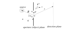
which is linear, isotropic, homogenous, non-dispersive and non-magnetic. Under these assumptions, all the components of the electromagnetic field are uncoupled and the space dependent part satisfies the Helmholtz wave equation at each source-free point:
| (1) |
For simplicity, we assume index of refraction equal to 1 so that . For diffraction by planar screens, equation (1) can be solved by following Kirchhoff in applying Green’s theorem,
| (2) |
where the integral is taken over the plane of aperture and signifies a partial derivative in the outward normal direction at each point on . The vectors and extends from the center of the aperture to the source and the screen respectively and scans the aperture plane (see Fig. 1). The field amplitude on the aperture plane is given by the spherical wave . If both the source and the detection plane are located in the far zone one can make use of the Fresnel and Fraunhofer approximations, , and the integral given in Eq. (S0.Ex1) can be carried out to obtain,
| (3) |
where A is a constant proportional to amplitude of the electric field at unit distance from the source, is the radius of the circular aperture, and is radius in the spatial frequency domain. Here is the radial distance to the optical axis on the detection plane. The intensity distribution associated with Eq. (3) is referred to as the well known Airy pattern. It is rotationally symmetric around the -axis. Figure 2 shows a cross section of the Airy pattern for an aperture size . The position of the first minima, measured along the radial axis, is given by . The width is also denoted as the Airy disk radius. The ability to resolve two apertures depends on the size of the Airy disk. The narrower the width, , is the better the resolution will be. For far field detection, Airy disk radius can be on the order of wavelength only if the size of the aperture is much larger than the wavelength itself. On the other hand, an aperture having a size of one wavelength will produce an Airy disk of radius , which is much larger than the wavelength because . The effective size of the diffraction pattern is seen to be inversely proportional to the linear dimensions of the aperture. This is a direct consequence of diffraction of waves and spreading comes from the uncertainty relation . In far-field optics, the upper bound for is given by the wavenumber of the object medium because we discard spatial frequencies associated with evanescent wave components. In this case the resolution cannot be better than and one can reconstruct a low-pass filtered version of the aperture.
Now, let us consider the setup in which the dipole is located very close to the aperture. In this case, Fraunhofer approximations are not valid in the region between the dipole and the aperture. Then, the integral given in Eq. (S0.Ex1) becomes,
| (4) |
where is a phase factor. Our aim is to compare this result with Eq. (3). To analyze the angular spectrum of the field one can expand the spherical wave into an angular spectrum of plane waves as given by Weyl’s [16] integral,
| (5) |
where,
| (6) |
is the source-aperture distance on the -axis and . By substitution from Eq. (6) and Eq. (5) into Eq. (S0.Ex2) it can be verified that the angular spectrum of has the following transverse wave vector component
| (7) |
This contains the source wave vector multiplied by the numerical aperture () and the lateral wave vector, , of the dipole. Therefore the spatial frequency exceeds that of Eq. (3) by . In principle, there is no upper limit for because a point source in space is characterized by an infinite spectrum of spatial frequencies , . A spherical wave is well localized in position but its momentum has a direction that is totally uncertain. For large , high frequency components are filtered out and we get, , i.e. the usual diffraction limit. On the other hand, for , the contribution coming from the higher spatial frequency modes, () can not be ignored. It is possible to collect higher spatial frequencies partially by locating the dipole closer to the aperture. Note that even for , the wave in Eq. (S0.Ex2) is propagating because of the phase factor .
To see the effect of the near field of the dipole we numerically calculate the intensity associated with the integral given in Eq. (S0.Ex2). Figures 2-2 represent the intensity of diffracted field for a given radius of the aperture and for different values of dipole-aperture distance, . The bandwidth of spatial frequencies increases as decreases, because the contribution coming from larger values increases as gets smaller in the integral given by Eq. (5).
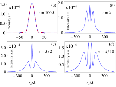
Comparing Fig. 2 to Figs. 2 we can understand how the near field of the dipole increases and changes the resolution of the object. Higher spatial frequencies, , which are totally lost in classical imaging (see Fig. 2) are partially converted into propagating waves. What we are showing is in a sense inverse of what one does in Fresnel diffraction as we keep the source distance much smaller than a wavelength. However the observation plane is in far field. The precise mathematical connection between our results and fresnel diffraction needs to be examined further using the rigorous wave equations.
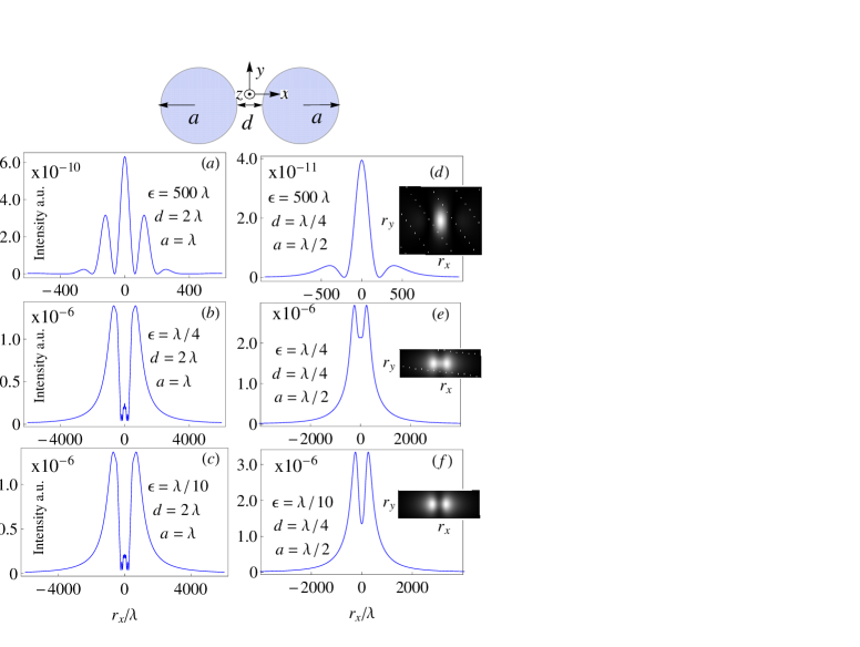
The far field resolution enhancement provided by the evanescent component of the dipole can also be considered for the diffraction by two closely located apertures. We calculate the far field using the same scalar diffraction integral in Eq. (S0.Ex2). This time the integration surface is chosen to be two circular holes as illustrated in Fig. 3. We choose the radii of the apertures to be and . We consider two different separation distances, and , measured from the rim. First we calculate the patterns for the source located in the far zone for comparison (see Figs. 3 () and 3 ()). The images look like an interference pattern from two slits and the objects are not resolved. As the source gets closer in the subwavelength range, the objects appear as two separated spots and they are resolved (see Figs. 3 and 3 ).
To summarize, we have described how the high spatial frequencies of a localized scalar field can be utilized to enhance the resolution of objects in the far zone. We use the scalar diffraction theory and the method of angular spectrum representation to compute the images numerically. The principle of enhanced image resolution is explained by analyzing the transverse wave vector component of the the diffracted field in the object plane. We also demonstrate how partially collected evanescent waves by the scalar dipole can resolve two closely located objects. The principle of resolution enhancement by using evanescent waves in this paper do not require a scanning probe or near-field detection schemes. Therefore, the far-field microscopy techniques can be employed for the image reconstruction.
A.K. is grateful to the Scientific and Technological Research Council of Turkey (TÜBİTAK) grant no 110T321 for supporting this research.
References
- [1] J.M. Vigoureux, F.Depasse, C. Girard, Appl. Opt. 31, 3036 (1992).
- [2] E. Wolf, J. Opt. Soc. Am. 60, 18 (1970).
- [3] G.S. Agarwal, Pure Appl. Opt. 7, 1143 (1998).
- [4] M.A. Paesler, P.J. Moyer, Near Field Optics(Wiley, 1996).
- [5] E. Betzig, J.K. Trautman, T.D. Harris, J.S. Weiner, R.L. Kostelak, Science 251, 5000, 1468 (1991).
- [6] Y. Oshikan, T. Kataoka, M. Okuda, S. Hara, H. Inoue, M. Nakano, Sci. Technol. Adv. Mater. 8, 181 (2007).
- [7] L. Novotny, Phys. Today 64(7), 47 (2011).
- [8] J.B. Pendry, Phys. Rev. Lett. 85, 3966 (2000).
- [9] N. Fang, H.S. Lee, C. Sun, X. Zhang, Science 308, 534 (2005).
- [10] J.M. Guerra, Appl. Opt. 29, 3741 (1990).
- [11] J.M. Guerra and W. T. Plummer, U.S. Patent 4, 681, 451 (21 July 1987).
- [12] S. Gerber, D. Rotter, M. Hennrich, R. Blatt, F. Rohde, C. Schuck, M. Almendros, R. Gehr, F. Dubin3, J. Eschner, New J. Phys. 11, 013032 (2009).
- [13] I. Aharonovich, S. Castelletto, D.A. Simpson, C-H Su, A.D. Greentree, S. Prawer, Rep. Prog. Phys. 74, 076501 (2011).
- [14] L. Rogobete, F. Kaminski, M. Agio, V. Sandoghdar, Opt. Lett. 32, 1623 (2007).
- [15] X. Chen, S. Götzinger, V. Sandoghdar, Opt. Lett. 36, 3545 (2011).
- [16] H. Weyl, Annalen der Physik 365, 481 (1919).
References
- [1] J.M. Vigoureux, F.Depasse, C. Girard , “Superresolution of near-field optical microscopy defined from properties of confined electromagnetic waves,” Appl. Opt. 31, 3036–3045 (1992).
- [2] E. Wolf, “Determination of the amplitude and the phase of scattered fields by holography,” J. Opt. Soc. Am. 60, 18 (1970).
- [3] G.S. Agarwal, “Subwavelength resolution using evanescent waves,” Pure Appl. Opt. 7, 1143–1149 (1998).
- [4] M.A. Paesler, P.J. Moyer, Near Field Optics(Wiley, 1996).
- [5] E. Betzig, J.K. Trautman, T.D. Harris, J.S. Weiner, R.L. Kostelak, “Breaking the Diffraction Barrier: Optical Microscopy on a Nanometric Scale,” Science, 251, 5000, 1468–1470 (1991)
- [6] Y. Oshikan, T. Kataoka, M. Okuda, S. Hara, H. Inoue, M. Nakano, “Observation of nanostructure by scanning near-field optical microscope with small sphere probe,” Sci. Technol. Adv. Mater. 8, 181–185 (2007).
- [7] L. Novotny, “From near-field optics to optical antennas,” Phys. Today 64(7), 47 (2011).
- [8] J.B. Pendry, “Negative refraction makes a perfect lens,” Phys. Rev. Lett. 85, 3966–3969 (2000).
- [9] N. Fang, H.S. Lee, C. Sun, X. Zhang, “Sub-diffraction-limited optical imaging with a silver superlens,” Science 308, 534–537 (2005).
- [10] J.M. Guerra, “Photon tunneling microscopy,” Appl. Opt. 29, 3741–3752 (1990).
- [11] J.M. Guerra and W. T. Plummer, “Optical proximity imaging method and apparatus,” U.S. Patent 4, 681, 451 (21 July 1987).
- [12] S. Gerber, D. Rotter, M. Hennrich, R. Blatt, F. Rohde, C. Schuck, M. Almendros, R. Gehr, F. Dubin3, J. Eschner, “Quantum interference from remotely trapped ions,” New J. Phys. 11, 013032 (2009).
- [13] I. Aharonovich, S. Castelletto, D.A. Simpson, C-H Su, A.D. Greentree, S. Prawer, “ Diamond-based single-photon emitters,” Rep. Prog. Phys. 74, 076501 (2011).
- [14] L. Rogobete, F. Kaminski, M. Agio, V. Sandoghdar, “Design of plasmonic nanoantennae for enhancing spontaneous emission,” Opt. Lett. 32, 1623–1625 (2007).
- [15] X. Chen, S. Götzinger, V. Sandoghdar, “99‘% efficiency in collecting photons from a single emitter,” Opt. Lett. 36, 3545–3547 (2011).
- [16] H. Weyl, “Ausbreitung electromagnetischer wellen uber einem ebenen leiter,” Annalen der Physik, 365, 481 (1919).