A Jumping Cylinder on an Incline
Abstract
The problem of a cylinder of mass and radius , with its center of mass out of the cylinder axis, rolling on an incline that makes an angle with respect to the horizontal is analyzed. The equation of motion is partially solved to obtain the site where the cylinder loses contact with the incline (jumps). Several simplifications are made: the analyzed system consists of an homogeneous disc with a one dimensional straight line of mass parallel to the disc axis at a distance of the center of the cylinder. To compare our results with experimental data, we use a Styrofoam cylinder to which a long brass rod was imbibed parallel to the disc axis at a distance from it, so the center of mass lies at a distance from the center of the cylinder. Then the disc rolls without slipping on a long wooden ramp inclined at , and respect to the horizontal. To determine the jumping site, the motion was recorded with a high-speed video camera (Casio EX ZR100) at 200 and 480 frames per second. The experimental results agree well with the theoretical predictions.
I Introduction
The motion of an homogeneous cylinder rolling without slipping on an horizontal surface, or on an incline, is a classical problem in most textbooks of Mechanics, but only a few of them address the same problems when the center of mass of the cylinder is out of its axis; actually, we only know two examples were this case is put forward as an end-of-the-chapter exercise. Moreover, we have only found three papers that deal with similar movements for symmetrical inhomogeneous bodies. To our knowledge, this is the first time that the stated problem is theoretical solved and experimentally corroborated.
II Theoretical solution
The simplest way to partially solve the equation of motion is through energy conservation. After the cylinder has roll a distance along the incline plane, its center has descended a distance and the center of mass has descended a distance , so the change in the potential energy is:
| (1) |
where is the total mass of the cylinder and m/s2 is the value of the acceleration of gravity at the place where the experiments are done.
If the initial conditions are such that the cylinder is at rest and the center of mass lies on a line perpendicular to the incline plane, then the change in the kinetic energy of the disc, after it has rotated an angle , is:
| (2) |
where is the cylinder s moment of inertia respect to the instantaneous axis of rotation .
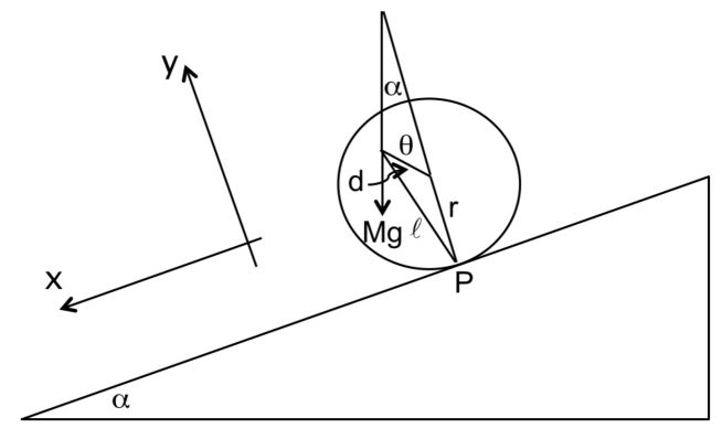
Taking a reference frame in which the -axis is along the incline plane, the -axis perpendicular to the same plane and the -axis perpendicular to the plane, the following relation holds between the different quantities involved in the problem (fig. 1):
| (3) |
where is the vector from the center of mass to the instantaneous axis of rotation , and the rotation angle. The magnitude of is:
| (4) |
so then , in virtue of the parallel axes theorem, is:
| (5) |
| (6) |
The condition the cylinder must satisfy in order to lose contact with the incline is that the normal to the incline component of the centrifugal force,
| (7) |
equals the normal component of the cylinder total weight, that is:
| (8) |
from which the following expression can be obtained:
| (9) |
A simple way to arrive to a solution of this transcendental equation is plotting together both sides and looking for the first intersection of the resulting curves. The results for , and are shown in figures 2, 3 and 4.
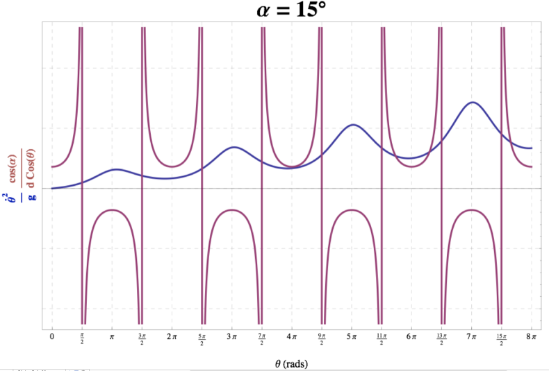
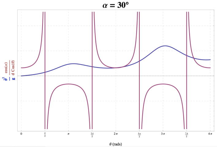
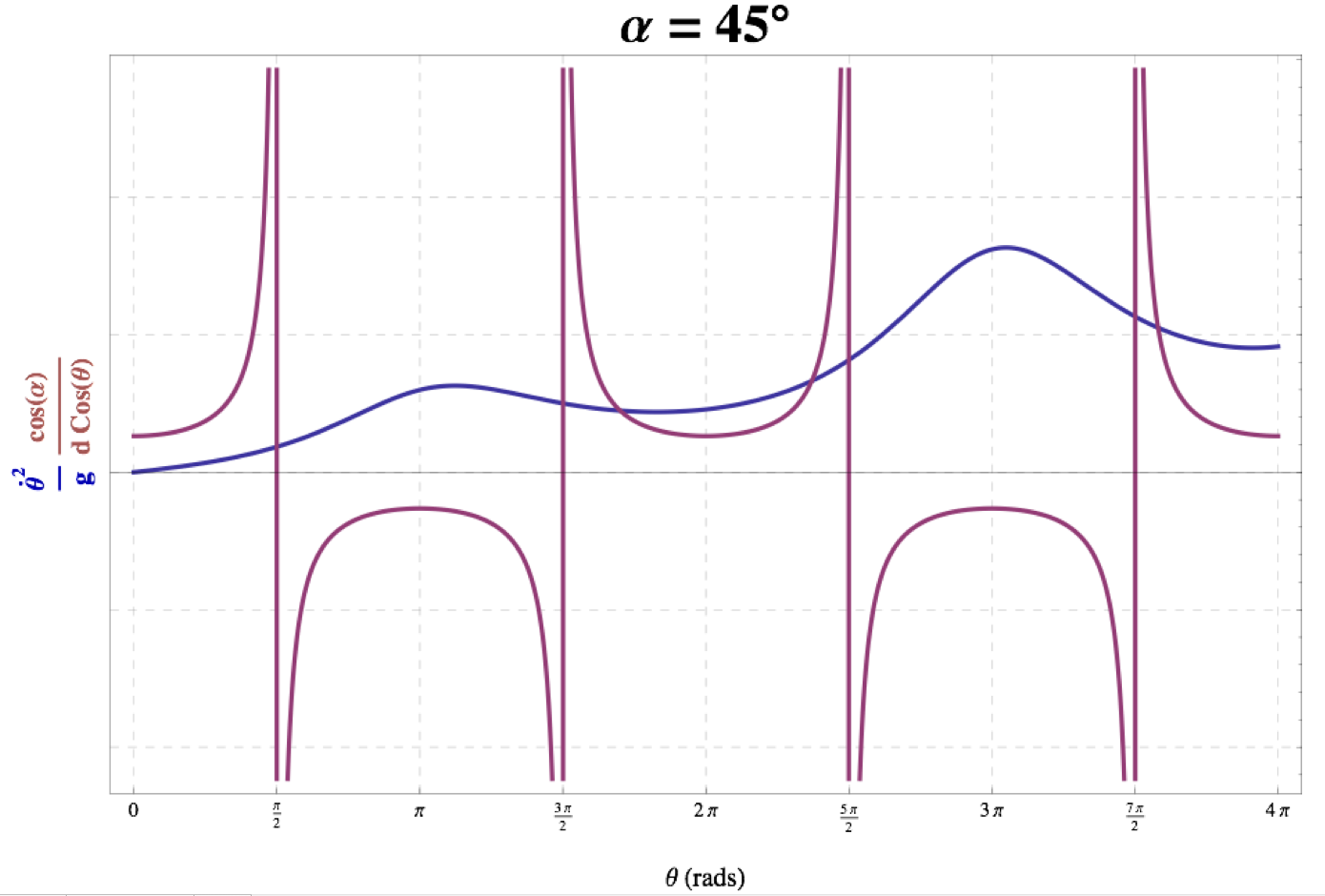
It is interesting to note the oscillation of the kinetic energy (proportional to the left side of Eq. 9) due to the centrifugal force effect produced at different positions of the center of mass of the cylinder.
III Experimental results
To compare our theoretical results with experimental data, we use a Styrofoam cylinder of radius cm, high cm and mass g, to which a mm diameter and cm long brass road of mass g was imbibed parallel to the disc axis at a distance cm from it, so the center of mass lies at a distance cm from the center of the cylinder. Then the disc rolls on a m long wooden ramp inclined at , and with respect to the horizontal. To determine the jumping site, the motion was recorded with a high-speed video camera (Casio EX ZR100) at 240 and 400 frames per second.
The main sources of errors in our experiment are the initial position of the cylinder, which was taken in such a way that its center of mass lied in the normal to the incline, and the place where the cylinder actually jumps. The initial position of the cylinder was done manually and we estimate an error of about . The jumping site is difficult to determine in the video, especially in case, because the jump takes place before disk has completed a whole turn and its speed is relatively small, so the jump is minute. We estimate a maximum error of about cm. in readings of the jumping site. Taking this into account, no error analysis was attempted; instead we report our experimental results in the jumping site with a maximum error of cm.
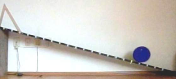
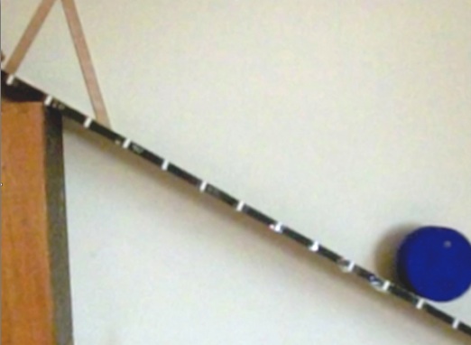
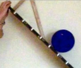
Figures 5, 6 and 7 are photograms, taken from the videos, of the jumping sites and in table 1 we compare the theoretical solution with the experimental results.
| Incline angle (degrees) | |||
|---|---|---|---|
| Theoretical jumping angle (rad) | |||
| Theoretical jumping position (cm) | |||
| Experimental jumping position (cm) |
Of special interest (to be seen in the videos) are: the case, were the speeding and the slowing down of the cylinder are clearly seen, and the spectacular second and third jumps in the case. The videos can be seen in the following YouTube web address:
http://www.youtube.com/watch?v=ITQYHU2ekMM .
IV Conclusions
A first integral of the equation of motion of a cylinder whose center of mass is not at its geometrical center, and rolls on an incline, is obtained. From this solution the site where the cylinder should jump is determine. An experimental setup, that resembles the assumptions made to obtain the theoretical solution, was furnished. The experimental results agree well with the theory. We believe that this is the first time that this problem is theoretically and experimentally addressed.
Acknowledgements.
This work was partially supported by DGAPA-UNAM IN115612, México.References
- (1) L.D. Landau and E.M. Lifshitz, Mechanics (Course of theoretical physics; v.1), 3rd ed. (Pergamon Press Ltd., UK., 1976), pp. 103.
- (2) de Jeans Wittenburg, Dynamics of Multibody Systems, Problem 3.5, (Springer-Verlag, Berlin Heidelberg, 2008).
- (3) Priya Narayanan, Rouben Rostamian, Uri Tasch, Alan M. Lefcourt, and Moon S. Kim, ”Rolling dynamics of an inhomogeneous ball on an inclined track,” http://www.math.umbc.edu/ rouben/rolling/rolling-ball.pdf
- (4) L.D. Akulenko, N.N. Bolotnik, S.A. Kumakshev, S.V. Nesterov, ”Control of motion of an inhomogeneous cylinder with internal movable masses along a horizontal plane,” Journal of Applied Mathematics and Mechanics 70, 843 858 (2006).
- (5) N.J. Balmforth, J.W.M. Bush, D. Venner and E.R Young, ”Dissipative descent: rocking and rolling down an incline,” Journal of Fluid Mechanics 590, 295-318 (2007).