Active Negative Index Metamaterial Powered by an Electron Beam
Abstract
A novel active negative index metamaterial that derives its gain from an electron beam is introduced. The metamaterial consists of a stack of equidistant parallel metal plates perforated by a periodic array of holes shaped as complementary split-ring resonators. It is shown that this structure supports a negative-index transverse magnetic electromagnetic mode that can resonantly interact with a relativistic electron beam. Such metamaterial can be used as a coherent radiation source or a particle accelerator.
pacs:
81.05.Xj, 41.60.Bq, 41.75.Lx, 07.57.HmArtificially structured metamaterials (MTMs) possess exotic macroscopic electromagnetic properties that cannot be achieved in natural materials. Constructed from simple planar elements such as split-ring resonators and thin wires smith_prl00 , MTMs enable a variety of applications such as “perfect” lenses, compact transmission lines and antennas, electromagnetic cloaks, and many others pendrylens_prl00 ; caloz_ieee05 ; ziolkowski_06 ; smith_cloak_06 . Negative refractive index veselago_68 ; smith_prl00 ; zhang_nature08 ; atwater_science07 is one of the most surprising and thoroughly studied properties enabled by MTMs. In this Letter we describe a new class of negative index MTMs that can strongly interact with an electron beam, thereby opening new opportunities for vacuum electronics devices such as coherent radiation sources and particle accelerators. The specific implementation of such a negative-index meta-waveguide (NIMW) analyzed in this Letter and schematically shown in Fig. 1 is obtained by patterning an array of split-ring resonator cutouts on the plates of a stack of planar metallic waveguides.
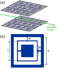
The NIMW belongs to the category of complementary metamaterials (C-MTMs) falcone . C-MTMs utilize the complements of the traditional split-ring resonators (SRR) in order to achieve a complementary electromagnetic response: an SRR exhibits a strong magnetic response while a C-SRR has a strong electric response. Narrow waveguides patterned with C-SRRs have been used smith_prl08 to demonstrate enhanced tunneling of transverse electromagnetic (TEM-like) waves. In this Letter we demonstrate that this structure supports a negative-index transverse magnetic (TM) mode: an electromagnetic mode propagating in the -direction, with being the only non-vanishing component in the waveguide’s mid-plane at . As demonstrated below, the negative effective permittivity of the NIMW is imparted to it by resonant C-SRRs falcone ; smith_prl08 , while the negative effective permeability is due to the transverse confinement of the TM modes shvets_prb03 supported by the narrow (width in the -direction is much smaller than the wavelength ) waveguides formed by the neighboring plates. The importance of utilizing TM modes lies in their ability to resonantly interact via finite with relativistic electron beams when their phase velocity is equal to the beam’s velocity . Such interaction can be exploited to either transfer the electromagnetic energy to the beam (particle accelerator) or to extract energy from the beam (coherent radiation source).
The attraction of the NIMW for coherent high-frequency radiation generation is four-fold. First, the opposite sign of the group velocity and the beam velocity can result in an instability utilized in backward-wave oscillators (BWO) or (for lower beam currents) amplifiers (BWA) tsimring . The sub-wavelength nature (lateral period ) of the NIMW supported by its resonant C-SRRs distinguishes it from the traditional BWOs which rely on the interaction between an electron beam and a spatial harmonic of the electromagnetic field in a periodic structure. Second, the low group velocity of the negative-index waves due to the NIMW’s resonant C-SRRs increases spatial gain, reduces the starting current requirement of a BWO, and enables shorter structures. Third, NIMW’s constitutive elements (C-SRRs) can be produced using standard planar fabrication techniques. This is particularly advantageous for the generation of THz and millimeter waves because the fabrication of conventional BWOs goebel_ieee94 relies on high-precision machining that becomes challenging for shorter wavelengths. Finally, the output radiation frequency of a NIMW can be accurately and rapidly controlled by electric or optical tuning of the resonant frequency of the C-SRRs padilla_nature06 . We note that the absolute instability of electron beams inside a negative-index medium has been suggested earlier bliokh , albeit limited to a hypothetical isotropic negative index material.
Below we demonstrate that the NIMW shown in Fig. 1 can be properly described as an effective bianisotropic marques_prb02 negative index medium for electromagnetic waves propagating in the -direction. By restricting the macroscopic (i.e. properly averaged over the metamaterial’s unit cell) electromagnetic field components to and , such metamaterial can be characterized by a set of constitutive parameters , , and the bianisotropy coefficient defined according to
| (1) |
and can be shown marques_prb02 ; ozbay to support electromagnetic waves propagating with refractive index given by
| (2) |
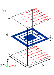
where the negative sign is assigned to the propagating waves with . To understand the emergence of negative-index waves in a NIMW, we first examine the origin of for wave propagation through a metamaterial composed of an array of planar waveguides with perfectly electrically conducting (PEC) walls stacked along the -direction. It is well established that a metamaterial composed by an array of metallic plates may be rigorously homogenized by studying the modes excited between any two neighboring plates rotman ; silveirinha . Here we apply this homogenization model to the parallel-plate metamaterial of Fig. 1a. A single cell of the array is shown in Fig. 2. The effective metamaterial properties are determined by the dominant TM mode, with wavenumber and frequency . We note that the longitudinal component of the electric field, enabled by the parallel-plates, can resonantly interact with an electron beam propagating in the -direction. The TM1 mode is symmetric with respect to the mid-plane, and possesses non-vanishing fields (even function of ), , and (both odd functions of ).
In anticipation of the need to emulate the effects of C-SRRs and the electron beam, the waveguide is assumed to be filled with a material characterized by a permittivity tensor with non-trivial components and , and a single non-vanishing component defined as in Eq.(1). Finite emulates magneto-optical coupling introduced by the C-SRR marques_prb02 , emulates resonant electric response of the C-SRR, while emulates the wave’s interaction with an electron beam when the resonance condition is satisfied.

The effective constitutive parameters may be computed by analyzing the propagation properties of the dominant TM1 mode, using the transmission-line characteristic impedances for forward and backward propagating TM waves according to , where the transmission line’s voltage and current are defined according to
| (3) | |||
and the top and bottom signs correspond to the forward and backward waves, respectively. While for an air filled transmission line shown in Fig. 2, that would no longer be the case when magnetoelectric coupling is present in the filling medium, as would be the case in the more general bianisotropic structure shown in Fig. 1. Effective material parameters can then be obtained from the transmission-line model through
| (4) |
where Ohm is the free-space impedance, and is the characteristic admittance of the transmission line.
Applying the above definitions of effective parameters and characteristic impedances to the mode of the conventional parallel-plate metamaterial in Fig. 2 made of smooth metallic plates and suitable filler medium, we obtain: and
| (5) |
resulting in the dispersion relation for the TM1 wave:
| (6) |
Several insights can be gained from Eq. (5). First, the effective magnetic permeability turns negative for , where is the cutoff frequency of the considered TM1 mode. Therefore, one approach to achieving negative-index propagation at is to pattern the waveguide’s wall in such a way as to ensure that . Second, if (as is the case for a beam resonantly interacting with the component of the mode), then , resulting in an active (gain) metamaterial. That the longitudinal component of the electric field (and, therefore, ) contributes to the effective magnetic permeability of confined TM modes has been known shvets_prb03 ; atwater_science07 from theoretical and experimental studies, but the possibility of employing an electron beam for controlling the imaginary part of and realizing gain in metamaterials has not been recognized. Finally, Eq. (6) can be recast in the conventional form for the theory of travelling wave tubes (TWTs) tsimring by assuming that the waveguide is filled with an active medium with permittivity , where is the electron beam plasma frequency. The resulting dispersion relation for the active NIMW can now be re-written as
| (7) |
where, because of the wave-beam interaction, the frequency is a complex number for a real propagation constant . Analogous to the linear theory of the TWT tsimring , Eq. (Active Negative Index Metamaterial Powered by an Electron Beam) is quartic in having four complex roots that represent three forward waves (with positive, negative, and zero gain) and one backward wave (not affected by the beam). The maximum gain is achieved at the beam-wave synchronism (zero detuning) condition, where is the dispersion relation without the beam, and the Pierce parameter tsimring of the NIMW is given by
| (8) |
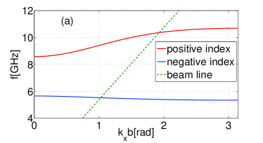
After gaining significant physical insights from analytic modeling of a smooth-walled structure, we proceed to extract the constitutive parameters of the NIMW shown in Fig. 1 through first-principles electromagnetic simulations using COMSOL Multiphysics comsol . Periodic boundary conditions along the and directions are used, and finite per-cell phase shift is assumed in the -direction. While the present design is for microwave frequencies ( GHz; physical dimensions are given in Fig. 1), it can be scaled down to mm-wave/THz frequencies. The dispersion relations of the lowest-order modes are shown in Fig. 3(a). A narrow-band negative index (NI) TM1-like mode is indeed found in the frequency range located below the cutoff frequency . Note that a second sub-cutoff TM1-like mode with positive refractive index is also supported by the structure. The positive index (PI) mode’s propagation is due to higher-order magnetic resonance of the C-SRR around GHz. This resonance strongly affects that enters Eq. (5) ( is assumed for the NI mode) and enables for GHz. Detailed discussion of the PI mode is outside of the scope of this Letter, and we concentrate below on the NI mode.
The mode-specific effective parameters of the NI mode were extracted by applying Eqs. (3,Active Negative Index Metamaterial Powered by an Electron Beam) to COMSOL-produced electromagnetic field profiles and plotted in Fig. 3(b) for moderate phase advances. We note that remains relatively flat, consistent with our original conjecture that the transverse confinement of the mode is responsible for its effective negative permeability. On the other hand, displays strongly dispersive behavior, consistent with its origin stemming from the resonant C-SRR element. We further observe that the bi-anisotropy coefficient is rather large and, consistent with Eq. (2), explains why both and are non-vanishing (negative) at the (cutoff) point, where is satisfied.
 |
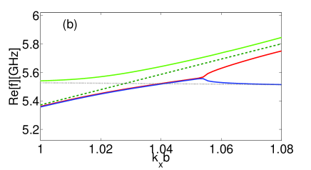 |
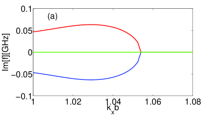
To examine the possibility of creating an active negative index metamaterial using a high-current electron beam coupled into the NIMW and to confirm the analytical predictions of Eqs. (Active Negative Index Metamaterial Powered by an Electron Beam,8), we have carried out COMSOL simulations of the NIMW structure containing an electron beam in the middle of the unit cell. The beam’s presence was modelled by assigning to the region occupied by the beam, and by assuming the following beam parameters: , beam plasma frequency , and the beam’s radius . The resulting complex , plotted as a function of the phase advance across the cell, is shown in Fig. 4 for phase advances in the vicinity of the beam-mode synchronism condition.
Three distinct complex ’s are found for each value of . Modal degeneracies can be classified according to the value of the detuning parameter . For two ”slow” modes with degenerate in are found, one of them exponentially growing and the other one decaying. The third, ”fast” mode with with is neutral (neither growing nor decaying) for . For all three modes (two ”slow” and one ”fast”) become neutral and non-degenerate in . These numerical COMSOL results compare very well with the analytical predictions of Eq. (Active Negative Index Metamaterial Powered by an Electron Beam) obtained by adjusting the effective beam plasma frequency to to account for only partial overlap between the beam and the negative-index TM mode. This reduction in is associated with small shunt impedance of the resonant NIMW, which concentrates the electric energy away from the beam in the vicinity of the C-SSR.
In conclusion, we have demonstrated a geometry to realize a novel active beam-driven negative index meta-waveguide (NIMW) that supports transverse magnetic (TM) waves capable of resonantly interacting with an electron beam. A number of novel vacuum electronics devices that require backward waves and small group velocity, such as backward-wave oscillators and amplifiers, can be envisioned based on this concept. The sub-wavelength nature of the unit cell enables strong interaction with electron beams at the fundamental harmonic of the structure, while the resonant nature of the constitutive elements (complementary split ring resonators) enables low group velocity and, potentially, agile frequency tuning. The narrow bandwith and small group velocity of NIMW increases its shunt impedance, making it a potentially attractive structure for advanced accelerator application. This work is supported by the US DoE grants DE-FG02-04ER41321 and DE-FG02-91ER40648.
References
- (1) D. R. Smith, W. J. Padilla, D. C. Vier, S. C. Nemat-Nasser, S. Schultz, Phys. Rev. Lett. 84, 4184 (2000).
- (2) J. B. Pendry, Phys. Rev. Lett., 85, 3966 (2000).
- (3) Y. Horii, C. Caloz, and T. Itoh, IEEE Trans. Microwave Theory Tech. 53, 1527 (2005).
- (4) R. W. Ziolkowski and A. Erentok, IEEE Trans. Antennas Propag. 54, 2113 (2006).
- (5) D. Schurig, J. J. Mock, B. J. Justice, S. A. Cummer, J. B. Pendry, A. F. Starr, and D. R. Smith, Science 314, 977 (2006).
- (6) V. G. Veselago, Soviet Physics – Uspekhi 10, 509 (1968).
- (7) J. Valentine, S. Zhang, T. Zentgraf, E. Ulin-Avila, D. A. Genov, G. Bartal, and X. Zhang, NATURE 455, 376 (2008).
- (8) H. J. Lezec, J. A. Dionne, and H. A. Atwater, Science 316, 430 (2007).
- (9) F. Falcone, T. Lopetegi, M. A. G. Laso et al., Phys. Rev. Lett 93, 197401 (2004).
- (10) R. Liu et. al.,, Phys. Rev. Lett. 100, 023903 (2008).
- (11) G. Shvets, Phys. Rev. B 67, 035109 (2003).
- (12) S. E. Tsimring, ”Electron beams and microwave vacuum electronics”, John Wiley and Sons, Inc., Hoboken, New Jersey, 2007.
- (13) D. M. Goebel et al, IEEE Trans. Plasma Sci. 22, 547 (1994).
- (14) H.-T. Chen, W. J. Padilla, J. M. O. Zide, S. R. Bank, A. C. Gossard, A. J. Taylor, and R. D. Averitt, Nature 444, 597 (2006).
- (15) Y. P. Bliokh, S. Savel’ev, and F. Nori, Phys. Rev. Lett. 100, 244803 (2008).
- (16) R. Marques, F. Medina, and R. Rafii-El-Idrissi, Phys. Rev. B 65, 144440 (2002).
- (17) W. Rotman, IRE Trans. Antennas Propag. 10, 82 (1962)
- (18) M. G. Silveirinha, A. Alù, and N. Engheta, Phys. Rev. E 75, 036603 (2007)
- (19) Z. Li, K. Aydin, and E. Ozbay, Phys. Rev. E 79, 026610 (2009).
- (20) RF Module, www.comsol.com, Comsol Inc., Burlington, MA 01803, USA
- (21) E. I. Smirnova et. al., Phys. Rev. Lett. 95, 074801 (2005).