Structural relationships among monoclinic and hexagonal phases and transition structures in Mg-Zn-Y alloys
Abstract
Isothermal ageing of plastically deformed Mg-Zn-Y alloys resulted in precipitation along twin boundaries. The bulky precipitates formed had structures similar to those recently reported for the rod-like precipitates, but afforded a more detailed study by high resolution TEM due to their larger size. The core of the precipitates often had the structure of monoclinic \ceMg4Zn7 phase, and had the orientation ; with either the matrix or the twin. On this \ceMg4Zn7 phase, hexagonal \ceMgZn2 phase grew in two orientations, both with . One of these orientations formed a known orientation relationship ; with the matrix. The part of the precipitate with the \ceMgZn2 structure was usually in direct contact with the twin boundary. Both \ceMg4Zn7 and \ceMgZn2 phases have layered structures that can be described with similar building blocks of icosahedrally coordinated atoms. The atomic positions of zinc atoms comprise the vertices of these icosahedra and form “thick” rhombic tiles. Orientation of these rhombuses remain unchanged across the interfaces between the two phases. Near the interface with \ceMgZn2, transition structures formed in \ceMg4Zn7 phase, with Zn:Mg atom ratio between those of \ceMg4Zn7 and \ceMgZn2 phases. In these transition structures, the unit cell of \ceMg4Zn7 phase is extended along [100] or [001] by half a unit cell length by continuation of the rhombic tiling. Structures of these extended unit cells are proposed.
aLightweight Alloys Group, Structural Metals Center, National Institute for Materials Science (NIMS), Sengen 1-2-1, Tsukuba, Ibaraki, 305-0047, Japan.
Keywords
Magnesium-zinc alloys, Precipitation, Orientation relationships, Interfaces, hexagonal Laves phase, Complex metallic alloys
1 Introduction
Magnesium alloys find application in automotive components and other areas where their strength to weight ratio is advantageous. The magnesium-zinc alloy system possesses the greatest precipitation hardening response of commercial Mg-based alloys [1] due to the precipitation of a fine, rod-like precipitate termed [1, 2, 3]. These precipitates provide resistance to basal slip, being highly elongated, with aspect ratios of around 40:1, and resistant to shearing by dislocations[1]. In fully aged samples the precipitates also significantly restrict deformation by twinning [4].
Despite the importance of this phase in strengthening Mg-Zn alloys, there has been on-going uncertainty regarding its structure. Early studies concluded that the rod-like precipitates possessed a \ceMgZn2 hexagonal Laves phase structure with lattice parameters a=0.52 nm, c = 0.85 nm[2, 5]. This view has also been supported by more recent studies [6]. Other investigators have proposed that the structure is instead that of a \ceMg4Zn7 monoclinic phase with lattice parameters a=2.596 nm, b=0.524 nm, c=1.428 nm, [7] and with a complex domain structure [8, 9].
Several orientation relationships (ORs) have been reported for the \ceMg4Zn7 phase in magnesium. In each case, the and directions lie parallel to one another, permitting good matching between the -lattice parameter (0.524 nm) and the hexagonal axis of magnesium (0.52 nm). The planes were aligned parallel to the planes [8, 9]. Other possibilities were orientation relationships with parallel to the or planes, or [5, 9].
The precipitate is metastable and further ageing of Mg-Zn alloys results in the precipitation of a plate-like phase, termed , on the basal planes of the Mg matrix. It is accepted that this hexagonal phase does possess the hexagonal Laves phase structure (with lattice parameters a=0.52 nm, c = 0.85 nm [2]) and orientation relationship ; [5, 10]. A lath-like form with ; [8] has also been reported as a minor variant.
Similar rod-shaped () and plate-shaped () precipitates are also observed in Mg-Zn-RE/Y (RE=Rare earth) alloys. These precipitates are thought to be identical in structure and composition to those in Mg-Zn alloys since rare earth elements and yttrium segregate to ternary phase precipitates at the grain boundaries [11] and have not been detected within the and precipitates [9, 11].
Among the ternary phases also exists the quasi-crystalline icosahedral phase (I-phase, )[12, 13]. This phase exists in equilibrium with -Mg phase, forming a two phase field when the atomic ratio of Zn:Y is near 6, as in the alloy studied here.
The monoclinic \ceMg4Zn7 and Laves phase \ceMgZn2 phases include zinc lattice sites which possess icosahedral symmetry and are thus are structurally related. The monoclinic \ceMg4Zn7 phase has been observed to co-exist with a decagonal quasi-crystalline approximant phase [14] and recent work has shown that \ceMg4Zn7 and \ceMgZn2 phases co-exist within the rod-like precipitates in Mg-Zn-Y alloys [15]. There appear to be structural similarities between the binary phases and the icosahedral phase and the monoclinic phase provides a model for the icosahedral structure[16]. A proper understanding of the relationships between the monoclinic and hexagonal phases would assist in clarifying their structural relationship to the i-phase and resolve the uncertainty regarding the phase present in the rod-shaped precipitates.
In the present work, extrusion followed by slight compression has been used to produce twins. Precipitation occurred along twin boundaries upon ageing. Twin boundary precipitates have been identified as belonging to \ceMg4Zn7 and \ceMgZn2 phases and to be larger in scale than the rods, with similar domain structures [17]. The larger size of the twin-boundary precipitates has offered an opportunity to examine the relationships between these precipitates in greater detail.
2 Experimental details
A magnesium alloy containing 2.8at.%Zn and 0.4at.%Y was produced via direct chill casting. The billet was homogenised at 350, for 15 h and extruded with extrusion ratio 12:1 at 300 to produce a 12 mm diameter rod. The extrusion process produced a tube texture, in which the basal planes lie parallel to the extrusion direction. For this texture, compression in the extrusion direction corresponds to -axis tension of Mg and results in extensive twinning at stresses just above the yield point [18, 19].
Cylindrical compression samples were machined from the extruded rod, encapsulated in helium, solution treated (400, 1 h) and quenched in water. An Instron mechanical tester was used to apply a total of 2.2% plastic strain at a strain rate of . The level of the plastic strain was chosen so as to be sufficient to generate deformation twins while limiting slip and dislocation multiplication. The alloys were aged at 150 in an oil bath for periods from 8 h to 48 h. Foils for TEM examination were prepared from the aged specimens, ground to and then thinned to perforation using a Gatan precision ion polishing system. A JEOL 4000EX instrument operating at 400 kV was used for high-resolution transmission electron microscopic analysis. Multi-slice image simulations were carried out using JEMS software using the pre-loaded parameters for the the JEOL 4000EX microscope [20].
3 Results
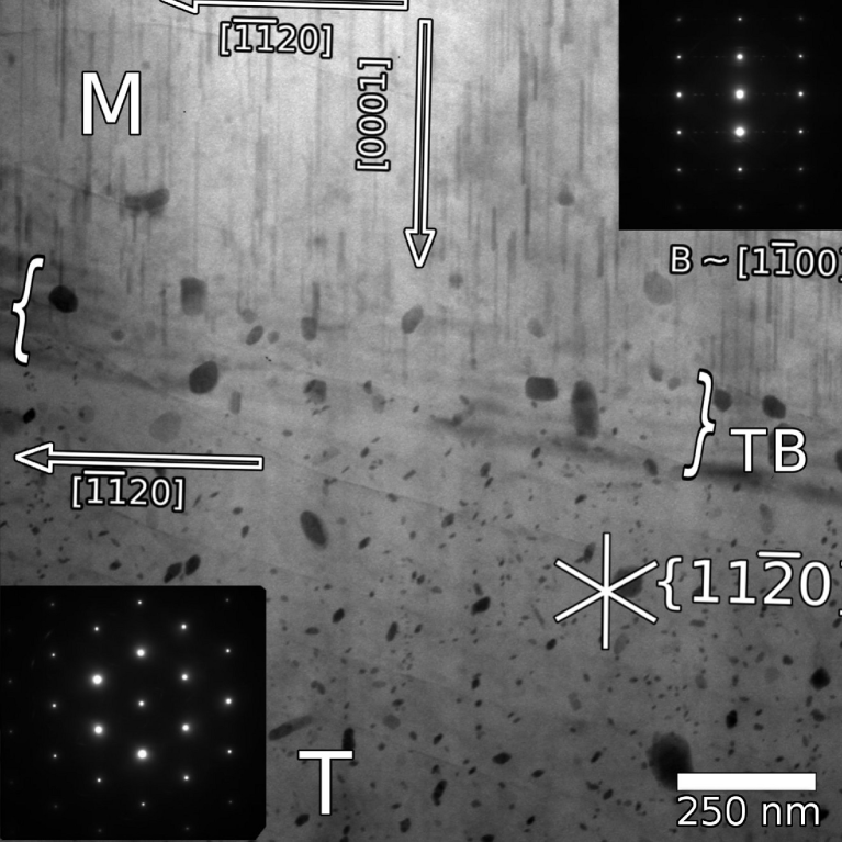
The microstructure of the alloys consisted of rod-like precipitates within both the magnesium matrix and the deformation twins, with larger, irregular precipitates present at the twin boundaries. Figure 1 presents a typical twin-boundary and the surrounding region. The matrix (M) is close to orientation, with the twin viewed along the zone. Rod-like precipitates can be seen side-on in the matrix and in cross-section in the twin. The twin boundary is inclined to the beam direction and is indicated by the bracketed region. A number of considerably larger, blocky precipitates can be seen along the twin boundary. The present work is concerned exclusively with twin-boundary precipitates, whose larger size permitted a close examination of their structure.
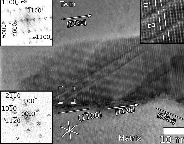
Hexagonal Laves phase precipitates were frequently observed on the twin boundaries, an example is shown in Figure 2. The matrix (lower portion) is viewed along the hexagonal axis (shown by FFT inset lower left) while the twin is 4o from its zone. The direction is common to both the regions. The precipitate has the known orientation relationship ; with respect to the magnesium matrix, as shown by FFT inset upper left. The interface with the matrix is faceted on the planes; facets on planes were also observed. The precipitate-twin interfaces which appear planar here were curved in most instances. The orientation relationship between the precipitate and the twin is ; . This retains the matching between and planes which exists between this precipitate and the matrix.
Planar defects were observed in these \ceMgZn2 precipitates, which were manifested in the FFT pattern like the one shown on the upper left in Figure 2. In this micrograph, the most visible defects are the diagonal lines across. Due to these defects, streaking occurred across the spots in the \ceMgZn2 pattern. These were of two kinds. When the diagonal defects were excluded from FFT, streaking occurred only along direction. This indicates stacking defects along the hexagonal axis. When the diagonal lines were included in the FFT, strong streaking occurred only along the reciprocal direction, perpendicular to the direction of these lines in the micrograph. The significance of these two kind of planar defects will be discussed in a later section.
Precipitates composed solely of the monoclinic phase were not observed on the twin boundaries. However, high resolution TEM images of the precipitates frequently showed regions of both \ceMg4Zn7 and \ceMgZn2 phases within the same precipitate. The precipitates in which the \ceMg4Zn7 and hexagonal Laves phases co-existed consisted of a central region of the monoclinic phase, with one or two variants of the hexagonal Laves phase in contact with it and with the magnesium matrix or twin.
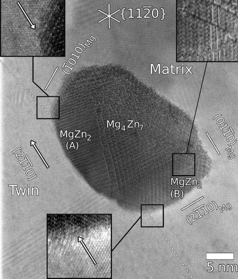
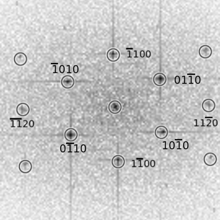
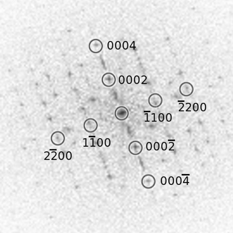
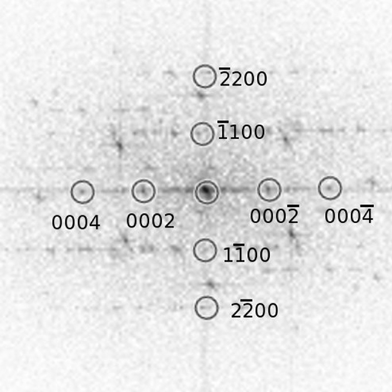
An example of such a dual-phase precipitate is presented in the HRTEM micrograph of Figure 3. The matrix is viewed along the hexagonal axis, as evidenced by FFT in Figure 3(b), while the twin region is close to the zone. The image was from a relatively thicker portion of the foil and was obtained close to the Scherzer defocus, which is about -45nm. The position of the twin boundary is indicated by the dashed lines and can also be seen in the enlarged insets showing where the precipitate is in contact with the twin boundary. The central region of the precipitate is in contact with the matrix and belongs to the \ceMg4Zn7 phase with the monoclinic structure clearly evident, and confirmed by indexing of the FFT shown in Figure 3(c). This central region of the precipitate has the orientation relationship ; with respect to the matrix. In all such precipitates, the monoclinic phase was found to form with the axis aligned with the [0001] direction of either the matrix or the twin, with no apparent preference for either region.
In the left and lower regions of this precipitate, the structure looks changed from the monoclinic in between. FFTs were obtained from these, shown in Figures 3(d) and 3(e). Both of these could be indexed to the \ceMgZn2 phase in zone axis . Thus regions A and B in Figure 3 are two differently oriented variants of the \ceMgZn2 phase, which are in contact with both the matrix and the twin.
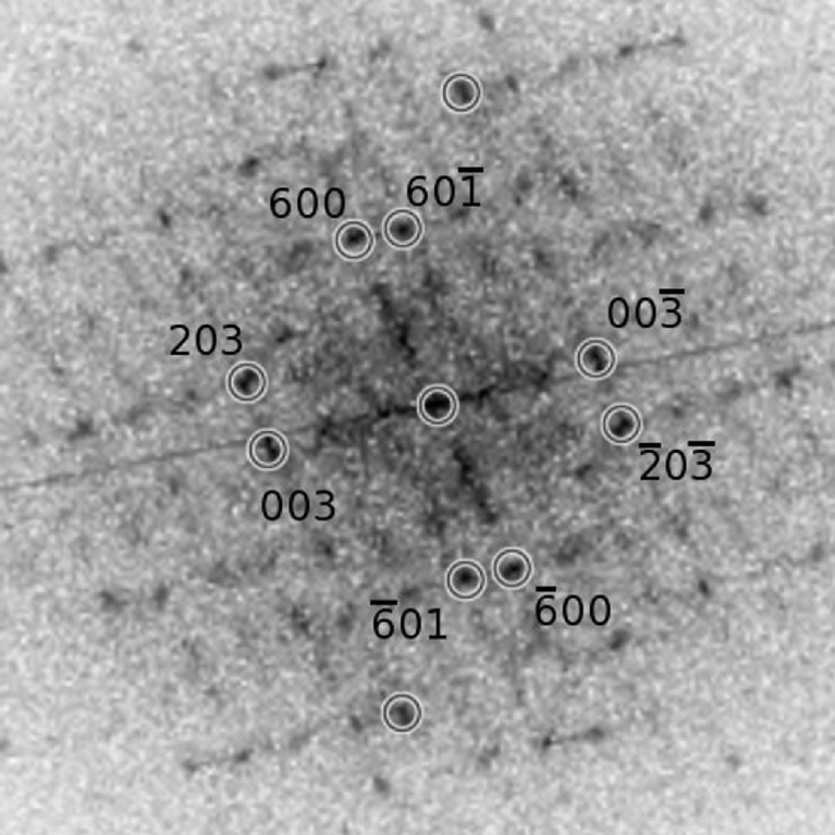
The FFT for the monoclinic phase (Figure 3(c)) contains a number of streaks lying parallel to the (100) and (001) planes. Similar features have been reported for rod-like precipitates of the monoclinic phase and the presence of a significant population of stacking faults or other planar defects was inferred [8, 9].
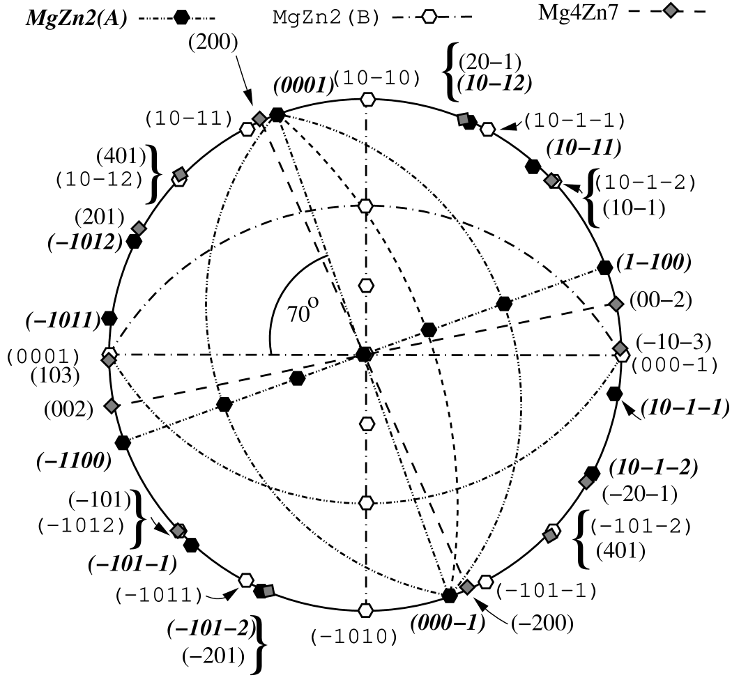
Based on these orientations, stereograms were plotted to see the ORs between the phases. The stereogram in Figure 4(a) shows the ORs between the matrix, the twin and the \ceMg4Zn7 phase. As mentioned before, the (201) plane of the \ceMg4Zn7 phase is along the plane of the matrix (). Another close match is . No perfect match between \ceMg4Zn7 and the twin () was found. However, a close match is .
Figure 4(b) shows stereograms of \ceMg4Zn7 phase and two orientations, A and B, of \ceMgZn2 phases which grow over it. A plane of the \ceMgZn2 phase in each orientation is parallel to the (010) plane of the \ceMg4Zn7 phase. The hexagonal plane of \ceMgZn2(A) matches with within a few degrees. A near perfect match is . In the case of \ceMgZn2 in orientation B, which shows a well-known orientation with the matrix, its hexagonal axis is close to . It also has close matches between and .
Both variants of the hexagonal Laves phase have the direction parallel to with respect to the matrix. This matching has been reported for intragranular precipitates of the Laves phase in these alloys [5, 6]. Figure 4(c) shows ORs of \ceMgZn2 in orientation A with the matrix and the twin. \ceMgZn2(A) in fact shows no other significant relationship with the matrix or the twin. One close match is .
A definite OR occurs between \ceMgZn2 in orientation B and the matrix and twin, shown in Figure 4(d). As known, and . No simple OR was found with the twin. The ORs between the phases are summarised in Table 1.


| Twin | Monoclinic | Laves(A) | Laves(B) | |
|---|---|---|---|---|
| -Mg | -\ceMg4Zn7 | -\ceMgZn2 | -\ceMgZn2 | |
| Matrix | ||||
| (Mg-) | ||||
| Twin | … | |||
| (Mg-) | ||||
| Monoclinic | … | … | ||
| (\ceMg4Zn7-) | ||||
| Laves(A) | … | … | … | |
| (\ceMgZn2-) |
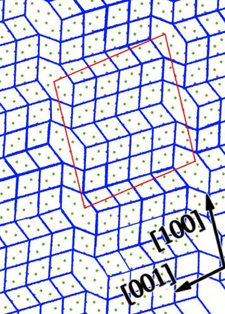
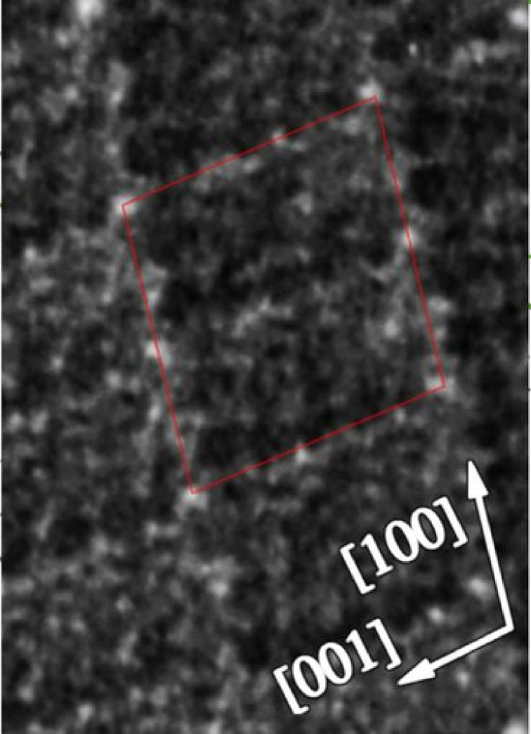
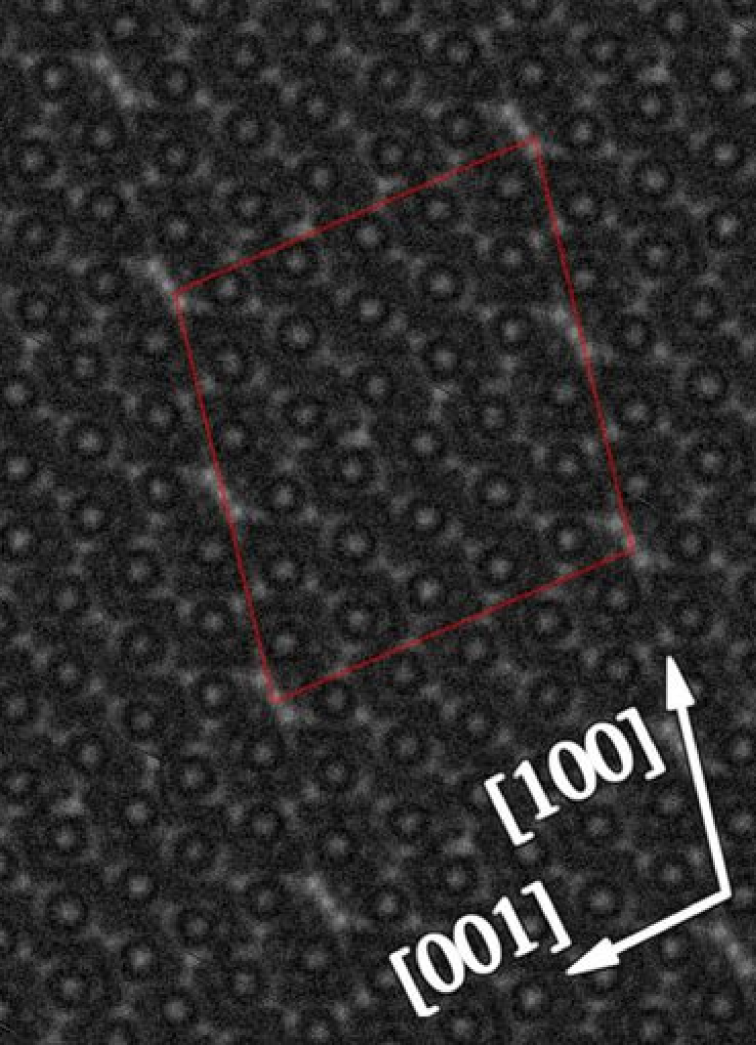
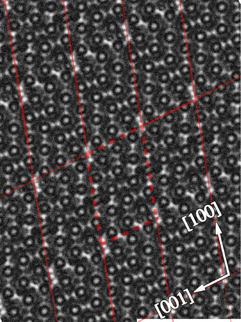
An enlarged micrograph of the same precipitate is shown in Figure 5 to show the interfaces between the monoclinic and hexagonal Laves phases in greater detail. It is possible to identify complete unit cells of the \ceMg4Zn7 structure (solid lines). The unit cells of the two differently oriented \ceMgZn2 hexagonal Laves phase structures (labeled and , respectively) are also indicated by solid lines. In between these three regions of central \ceMg4Zn7 structure and A and B, cells can be recognised which resemble those of the \ceMg4Zn7 structure but with different dimensions. Under the present imaging conditions the corners of the \ceMg4Zn7 unit cell, and the midpoints of the planes appear as brighter spots, corresponding to magnesium-rich sites within the structure. The spacing between these sites increases close to both interfaces with the Laves phase indicating a change in the lattice spacing in either the [100] or the [001] direction. Aside from the increased spacing between the magnesium-rich sites, there did not appear to be any significant changes to the structure. These regions are considered as transition structures in between \ceMg4Zn7-\ceMgZn2, which are related to but distinct from the \ceMg4Zn7 structure. These are indicated by dashed lines, denoted and , and described in greater detail.
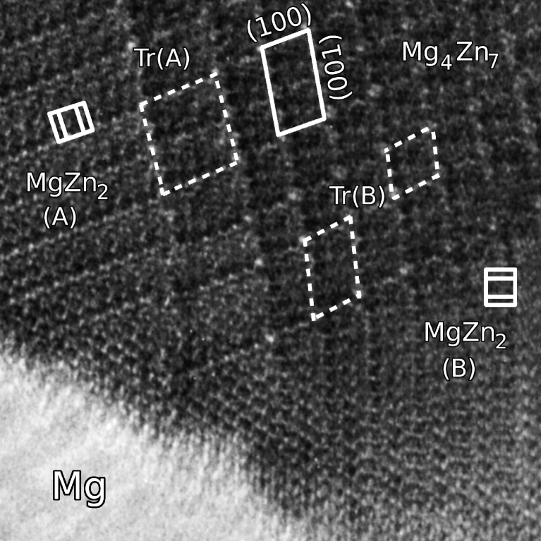
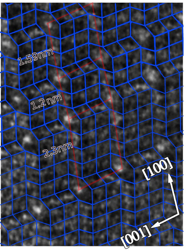
The presence of these transition structures suggests that the structure has undergone not a sudden but a gradual transition between the \ceMg4Zn7 and \ceMgZn2 structures. Transition structures with monoclinic cells, (labelled and ) can be identified near the \ceMg4Zn7-\ceMgZn2 interfaces and are indicated by dashed lines. The spacing between magnesium-rich sites at was 2.6 nm and 2.42 nm in the and directions respectively. Two cells are outlined in where the spacing remained = 1.48 nm parallel to , and was measured at 1.59 nm and 2.3 nm parallel to in the two cells illustrated by the dashed lines.
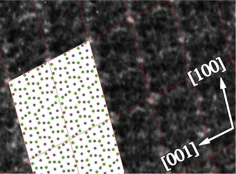
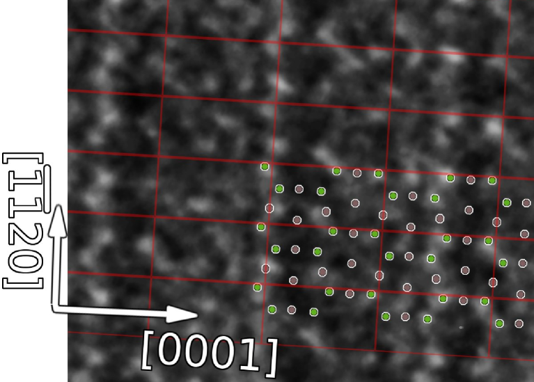
The HRTEM images were compared with multi-slice simulations of the \ceMg4Zn7 and \ceMgZn2 phases produced using JEMS software [20] and are presented in Figure 6. Image simulations were produced for defocus values from 0 to 120 nm and foil thicknesses up to 80 nm. The region of the HRTEM image selected was that indicated in Figure 5 by the outline of the relevant unit cell. Figures 6(a,b) show experimentally obtained images, overlaid with projected atomic positions and the unit cell boundaries within the monoclinic and the hexagonal Laves phases, respectively. Multi-slice simulation for these structures are shown in Figure 6(c,d). The simulation shown are for a defocus of 75 nm, with a specimen thickness of 73.6 nm.
In both experimental and simulated images of the monoclinic phase, the most prominent features are sites of strong contrast at the corners of the unit cell and at the sites of the monoclinic unit cell. These are spaced approximately 12.5 nm in the [100] direction, and 14.5 nm in the [001] direction, as expected for the \ceMg4Zn7 structure.
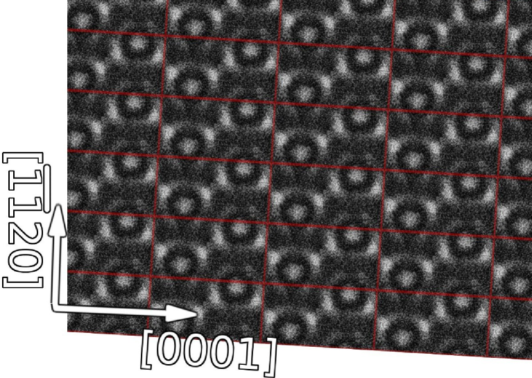
These strongly contrasting sites present in the \ceMg4Zn7 phase were not present for the hexagonal phase. however, in other respects the simulations are similar, owing to the presence of similarly co-ordinated atoms in each structure. The Laves phase simulation shows a good qualitative match with the experimental image in terms of atomic positions. Both experimental and simulated images show a zig-zagged pattern of stronger contrast centred on the basal planes for . In the experimental image, this feature was strongly enhanced for for every 1.5 unit cell heights. This feature was thought to be due to ordering on this plane, which is dealt with in a companion work [15].
4 Discussion
The present work has shown that both \ceMg4Zn7 and \ceMgZn2 phases form along deformation twin-boundaries in Mg-Zn-Y and that the \ceMg4Zn7 and \ceMgZn2 phases can co-exist as distinct regions within a single precipitate. In agreement with earlier studies [9, 11], the precipitates showed no evidence of definite yttrium enrichment and are therefore taken to consist of binary Mg-Zn phases. Microdomain structures have been reported in precipitates [8, 9] and co-existence of the \ceMg4Zn7 and \ceMgZn2 phases has recently been indicated in rods [15]. However, in the larger-scale twin-boundary precipitates examined herein it has been possible to identify distinct regions of nanometer scale belonging to each phase and to examine the \ceMg4Zn7-\ceMgZn2 interfaces.
Two features deserve particular note; the orientation relationship between the two precipitate phases and the presence of monoclinic transition structures at the interface between \ceMg4Zn7 and \ceMgZn2. The significance of both features will be discussed in terms of the structural similarities between the \ceMg4Zn7 and \ceMgZn2 phases.
4.1 Structural and orientation relationships between \ceMg_4Zn_7 and \ceMgZn_2 phases
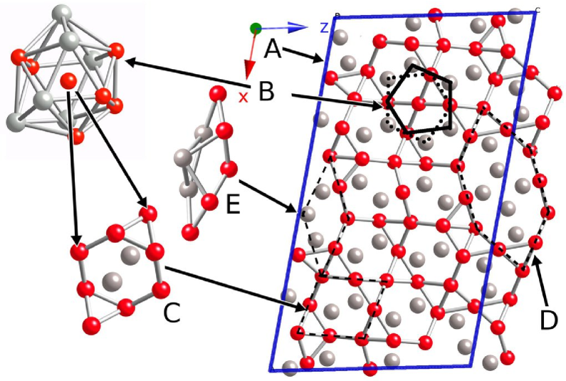
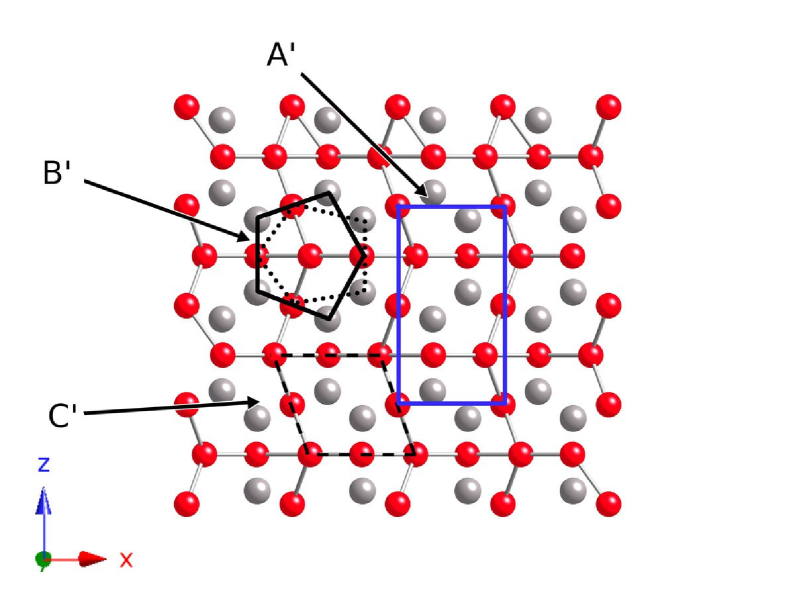
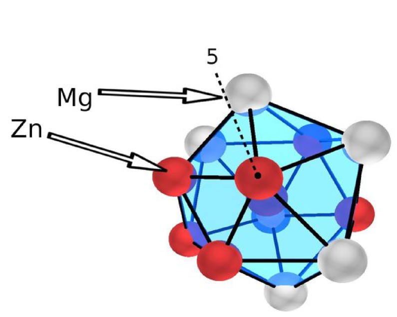
The structures of the monoclinic and hexagonal Laves phases are illustrated in Figure 7. Figure 7(a) shows the monoclinic structure along a [010] axis, while Figure 7(b) shows the hexagonal Laves phase structure along the axis. Unit cell boundaries for the two phases (A and A’, respectively) are indicated by thick lines. Both phases contain icosahedral clusters centred on zinc atoms (indicated at points B and B’. respectively), with pentagonal layers above and below these zinc atoms. The upper and lower pentagonal layers are rotated 180o with respect to each other [16].
The structure can also be viewed as a series of face-sharing “thick” rhombic tiles, with acute angle , with the vertices of the rhombic tiles occupied by zinc atoms which form the vertices of the icosahedral coordinations. Thick rhombic tiles are outlined at points C and C’, respectively. Each “thick” rhombic unit has a composition of and a continuous patterning of such units satisfies the overall \ceMgZn2 composition of the hexagonal Laves phase. In the hexagonal Laves structure, the rhomboids are arranged with the acute angle alternating right to left. In contrast, the monoclinic structure in has acute angles directed Right-Right-Left.
The monoclinic structure also contains hexagonal units at the corners and sites. These can be further decomposed into “thin” rhombic tiles (D) (acute angle ) which are absent from the hexagonal phase. Each such unit is zinc-deficient relative to the Laves phase composition and these serve to establish the \ceMg4Zn7 composition.
When formed in the matrix, the monoclinic and hexagonal phases adopt axial orientations in which the hexagonal axis of magnesium is parallel to and to one of the directions, respectively. This permits good matching between the basal plane of Mg (0.520 nm) with (0.524 nm) [7, 8] and (0.261 nm). The change in crystallographic orientation across the twin boundary makes it impossible for an entire precipitate consisting of either \ceMg4Zn7 or \ceMgZn2 to sustain such a relationship with both matrix and twin. The monoclinic phase for example (space group #12, with ) is not able to simultaneously adopt any favourable planar matching with both matrix and twin, as can be seen in the stereogram in Figure 4(a).
The hexagonal Laves phase, however, is able to assume more favourable orientations across the twin boundary. For precipitates of the hexagonal phase on the twin boundary, as in Figure 2, the phase is close to a previously-reported orientation to the matrix [10], with ; . In this orientation the planes will also be near-parallel to the planes of the twin.
In the mixed phase precipitates, the monoclinic phase was observed with the previously reported orientation relationships to Mg for the (\ceMg4Zn7) rods formed in the matrix [8, 9] and could be oriented with respect to either the matrix or twin. For the example shown in Figures 3 and 5 the orientation relationship was ; with respect to the matrix.
When the hexagonal Laves phase co-existed with the monoclinic structure, one region of the Laves phase (B) adopted the known orientation ; [8, 11]. The other hexagonal region (A) did not have closely matching lattice planes with respect to either matrix or twin and at first glance its presence appears difficult to explain.
It is possible, however, to demonstrate that the rhombic subunits present in \ceMg4Zn7 and \ceMgZn2 remained aligned when \ceMg4Zn7 was in contact with either variant of \ceMgZn2. Figure 8 presents schematics of the \ceMg4Zn7 and \ceMgZn2 phases oriented with respect to one another as in Figure 5 and shows that the orientation is not related by the unit cells, but through the constituent rhombic units. The unit cells for each structure are shown in solid lines, with the rhombic units outlined. It can be seen that the rhombic units within the \ceMg4Zn7 phase are accurately aligned with those of the two hexagonal Laves phase regions, and in principle at least, it appears possible to construct a well-matched interface for the two phases in this manner. It should be noted that in order to do so, a series of defects must be introduced parallel to the basal planes of the hexagonal Laves phase, with a spacing of 1.25 nm. Enhanced contrast with this spacing was observed in the experimental images for the hexagonal phase, which was not produced by the multi-slice simulations for the \ceMgZn2 structure (Figure 6(b,d)). This would also be a source of stacking defects on c-planes observed in Figure 2.
The existence of such a relationship between the rhombic units and the absence of a unit-cell based correspondence with either monoclinic phase or magnesium suggests that it is the rhombic units which are the determining factor in deciding the orientation of the hexagonal Laves phase. The real interface is likely to be more complex than is set out in Figure 8, particularly in terms of the introduction of defects and the presence of the transition structures. However, it appears likely that there will be good, possibly near-continuous, matching between the rhombic units making up the monoclinic and hexagonal phases.


No regularity was found in the stacking defects observed along the hexagonal axis of \ceMgZn2 phase observed in Figure 2. Another type of planar defect parallel to were pointed out in Figure 2. These defects are along only one direction and not on equivalent planes. These defects have a finite width, and across them, the (0001) planes were shifted by about half the interplanar distance. A rhombic unit can be defined in these defects. Therefore it can be assumed that these defects are also from the relationship of the \ceMgZn2 phase with the \ceMg4Zn7. In the stereogram of Figure 4(b), a {101} plane is nearly parallel to (200) plane. In fact, when looked closely enough, such a defect is also observed in \ceMgZn2 (B) in Figure , in its upper portion. It is quite possible that the apparently single \ceMgZn2 precipitates on the twin boundaries are also part of dual phase precipitates.
4.2 Transition structures
The existence of the transition structures at the \ceMg4Zn7–\ceMgZn2 interfaces (Figure 5) is a key observation. These are structurally related to both phases, being constructed in a modular fashion from identical rhombic units present in both \ceMg4Zn7 and \ceMgZn2 phases, plus hexagonal units found in the \ceMg4Zn7 phase. The crystal structure remains monoclinic but with enlarged unit cells, given in Table 2.
Such structures can be constructed from the standard \ceMg4Zn7 structure by extending the tiling of rhombic units. If the unit cell is extended by the addition of two rows of rhombic tiles in the [001] directions it corresponds to transition structure in Figure 5 with the \ceMg4Zn7-\ceMgZn2 interface parallel to the plane. The cell can also be extended in the [100] direction, by the addition of two rhombic subunits, corresponding to one of the transition structures, , at the \ceMg4Zn7-\ceMgZn2 interface parallel to the plane.
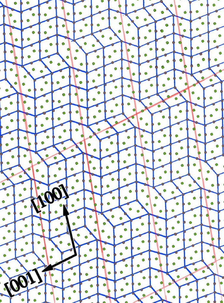
Simulations for the transition structures of regions and are shown in Figure 9. The proposed transition structure for region is shown in Figure 9(b), with the unit cell and rhombic units overlaid. This structure was generated from that of \ceMg4Zn7, but with the addition of two additional rhombic units in the [001] direction, resulting in an enlarged monoclinic structure with the same symmetry as the original phase. There is good agreement between the experimental image (Figure 9(d)) and simulation (Figure 9(f)), both of which appear very similar to the \ceMg4Zn7 structure, except for the greater spacing of the strongly contrasting sites Mg-rich. The transition region for this interfaces is equivalent in width to one unit cell of the extended structure.
Region is somewhat more complex. The transition region for this (100) interface had a width of 4.1 nm, but with considerable variation within this region. In the experimental image (Figure 9(d)) three regions can be identified, based on the spacing of the strongly contrasting sites in the [100] direction. The central region has a spacing of 1.25 nm between such sites, equivalent to nm for the \ceMg4Zn7 structure. Adjacent to this are bands with spacings of 1.59 nm (above) and 2.3 nm (below) between such sites. In the rhombic units overlaid on the image it can be seen that this corresponds to the addition of one and two rhombic units of the \ceMg4Zn7 structure per half-unit cell length. These three regions correspond to half-unit cells () of the \ceMg4Zn7 structure and two related structures with the addition of more rhombic units between the strongly-contrasting magnesium-rich sites. Figure 9(b) sets out a structure based on that of \ceMg4Zn7 and with the same symmetry, but extended by four rhombic units in the [100] direction, in which a half-unit cell length A half unit cell length of this structure (indicated by a dashed line in the simulation in Figure 9(f)) matches moderately well with the observed spacing of 2.3 nm.
The transition structure were also clearly related to the \ceMg4Zn7 and \ceMgZn2 phases in terms of orientation, with the tiling of the rhombic and hexagonal blocks appearing to running continuously through interface region.
| Lattice parameters | ||||||
|---|---|---|---|---|---|---|
| Structure | /nm | /nm | /o | |||
| \ceMg4Zn7 | 2.596 | 1.448 | 102.5 | |||
| 2.596 | (2.6) | 2.389 | (2.42) | 99.4 | (100) | |
| 4.371 | (4.5)* | 1.448 | (1.48) | 107.3 | (109) | |
*2.25 nm for the half-unit cell illustrated in Figure 9.
The transition structure described above are clearly only examples and it would be possible to construct a range of such structures from the rhombic and hexagonal units described in Section 4.1. The transition structures are larger in unit cell size than \ceMg4Zn7 and the hexagonal units comprise a smaller proportion of the structure, which will have a Mg:Zn ratio between the Laves and \ceMg4Zn7 monoclinic structures i.e. compositions will be in the range . This indicates that there may be gradual variations in composition across the \ceMg4Zn7-\ceMgZn2 interfaces, however this system appears able to accommodate precipitates with compositions between these two values, so long as such structures as constructed principally of the acute rhombic unit present in both \ceMg4Zn7 and \ceMgZn2 phases.
4.3 The origin of the mixed-phase precipitates
It is quite clear that is a transition precipitate. The precipitation sequence within the matrix is well known to commence with the precipitation of rods in the under-aged condition, followed by the plates upon overageing [2]. The plate-shaped precipitates in the over-aged condition have long been associated with the \ceMgZn2 structure, while the rods present at earlier stages of ageing have been identified as either \ceMg4Zn7 [8, 9] or \ceMgZn2 [2, 5, 6]. While both phases examined here are metastable intermediates (the equilibrium phase having a composition MgZn and a rhombohedral structure [21]) it is logical to conclude that the \ceMgZn2 phase is thermodynamically more stable than \ceMg4Zn7, since that latter is only observed in the under-aged or peak-aged condition.
In the present work, the precipitates were examined in a condition close to peak age and the predominant precipitate in the matrix (and twins) were rods, which appeared to have a \ceMg4Zn7 structure. The twin boundary precipitate were considerably larger in volume and consisted of either hexagonal \ceMgZn2 or dual-phase \ceMg4Zn7-\ceMgZn2. As such the twin-boundary precipitates appear to have progressed further towards equilibrium that those in the matrix, both in terms of the presence of the \ceMgZn2 phase and in the greater size which has been achieved.
The dual-phase precipitates were comprised of a central region of the monoclinic phase, which was always found to adopt one of the previously reported orientation relationships to either the matrix or the twin. In contrast, the hexagonal phase sometimes formed with an orientation relationship to the matrix (e.g. region B in Figure 5) and sometimes showed no clear lattice matching to the matrix or twin (e.g. region A in Figure 5). Despite this difference, both variants possessed an orientation relationship to the monoclinic phase via the rhombic units. This, together with the presence of the monoclinic structure at the centre of each mixed-phase precipitate implies that this phase formed prior to the hexagonal Laves phase, with the latter phase growing on the monoclinic phase.
It is unclear why the nucleation of \ceMg4Zn7 occurs first. Though it is not the most stable phase by the phase diagram, the stability of small sized precipitates will be predominantly affected by the interfacial energies. The morphologies will be dictated by the relative interface energies of the precipitate-matrix interfaces. Assuming precipitates to be \ceMg4Zn7, its rod-like morphology is dictated by need to minimise the area of the high energy interface. This optimises matching between the basal planes of the magnesium matrix and the planes. In the plate-like precipitates, interface appears to be a preferred, low energy interface and its area is maximised in this morphology.
The dual-phase precipitates are formed directly in contact with the twin boundary and it is clearly necessary to recognise that the twin boundary presents a different environment from the matrix. For example, pipe diffusion along the twin boundary would provide solute at accelerated rates compared to the bulk [9], assisting in the formation of larger precipitates along the twin interface. In addition, both rod shaped and twin boundary precipitates are of nanometer scale, with high surface energy to volume ratios, and the interfacial energies may play a significant role in controlling precipitation. As the precipitates grow and their interface to volume ratio decreases, the phase equilibria may change. A modification of the structure may occur to lower interface energies. The change in orientation of the Mg phase across the twin boundary is therefore particularly important since the precipitate is not able to adopt the preferred orientation (and hence form the preferred interfaces) to both matrix and twin.
One addition factor that may favour the formation of \ceMgZn2 in the twin boundary precipitates is the existence of \ceMg4Zn7 at the twin interface. Given the structural similarities in the form of these rhombic subunits between the \ceMg4Zn7 and \ceMgZn2 phases, and the alignment of such units, (as described in Section 4.1) it is proposed that this feature allows the \ceMg4Zn7 phase to provide a favourable surface on which the Laves phase can precipitate. This kind of structurally-similar interface may have permitted the hexagonal phase to form, even when (as with region A in Figure 5) it does not possess a good lattice match with the matrix or twin. This factor would permit the ready nucleation of the \ceMgZn2 phase at the twin boundaries where pre-existing \ceMg4Zn7 precipitates provide suitable nucleation sites.
The co-existence of the monoclinic and hexagonal phases in the twin-boundary precipitates may provide an explanation for the identification of the rod-shaped precipitates as either \ceMgZn2 [2, 5, 6] or \ceMg4Zn7 [8, 9]. It has been shown here that the two phases can co-exist in these larger, twin-boundary precipitates, while maintaining a clear correspondence between the rhombic units within the two structures. In addition, the presence of several structurally-similar transitional phases at the \ceMg4Zn7-\ceMgZn2 interfaces indicates that considerable structural and compositional variability can be accommodated within the precipitates. A related investigation focused specifically on the rod-like precipitates also identified both \ceMg4Zn7 and \ceMgZn2 within the rod-like precipitates [15]. It appears probable therefore, that the rod-like precipitates could be composed of either or both monoclinic and hexagonal phases plus a wide range of transitional structures, giving rise to the micro-domain structure reported in the literature [8, 9].
4.4 Structural relationship with quasi-crystalline phases
The \ceMg4Zn7, \ceMgZn2 and transition structures are essentially modular assemblies or similarly co-ordinated atoms. As such, it is worthwhile to consider their relationship, not only to one another but also to the quasi-crystalline i-phase found in Mg-Zn-Y alloys.
Although the \ceMg4Zn7 phase has been considered as related to the icosahedral phase directly [16], it can be better described as a decagonal quasi-crystal approximant. Coexistence of decagonal phase and \ceMg4Zn7 phase and the orientation relationship between them has been reported as ; and [14]. Approximant phases to decagonal quasi-crystals can be orthorhombic or monoclinic. Their structure can generally be described as layered. In case of monoclinic approximants, the unique axis corresponding to the decagonal axis, and the monoclinic angle is often close to 72o (i.e. ). The length of the unique axis is nearly equal to (or a multiple of) the periodicity of the decagonal phase in that alloy system. A well known decagonal approximant in aluminium alloys is , or [22, 23, 24].
A decagonal phase was reported in Zn-Mg-RE alloys[25]. The periodicity of this decagonal phase (along the periodic decagonal axis) is reported to be 0.255 nm. This is comparable to the lattice spacing along (020) of \ceMg4Zn7 and (0002) of magnesium. Two crystalline phases related to the decagonal phase were identified to be \ceMgZn2 and \ceMg4Zn7, the latter of which coexisted with the decagonal phase [26]. Compositionally, only a 2at% addition of Dy to the \ceMgZn2 phase formed the composition of the decagonal phase[27].
In hexagonal phases related to quasi-crystalline phases, the hexagonal axis corresponds to icosahedral twofold axis [28, 29, 30]. There are icosahedral clusters in three orientations, making the hexagonal symmetry. The \ceMgZn2 phase, however, is a simpler phase in which the hexagonal axis corresponds to a threefold axis of the icosahedral coordination. All icosahedra are thus similarly oriented. When viewed along a axis, pentagonally coordinated layers are observed, as in Figure 7(b). These pentagons are arranged in a row and have opposite orientations in the layers at two different levels (making two parts of icosahedra in the same orientation).
Often, domains of two phases in a grain are known to create diffraction patterns resembling those from a decagonal phase, such as in Al-Mn[31, 32, 33] and Al-Mn-Ni [34]. In the present study, which is on Mg-Zn-Y alloys, the coexistence of the two phases related to decagonal quasi-crystal and their intimately mixing in each other is analogous.
In the present phases, \ceMg4Zn7 and \ceMgZn2, the rhombic tiles of the intermediate layers form the structural units. The vertices of these rhombuses form the vertices of the icosahedral units. In the \ceMg4Zn7 structure, the main rhombic units, forming a unit of four, have an angle 72.5o, as shown at in Figure 7(a). These units are connected by rhombuses with an angle 71.5o. There is one more type of rhombus with an angle 67.5o, and a triangular and a near rectangular unit. In between the unit cells, a thin rhombus ( in Figure 7(a)) can be defined, with an angle of about 37o. The \ceMgZn2 structure is composed of only one type of rhombus with an angle 72o, whose direction alternates ( in Figure 7(b)). The two domains of \ceMgZn2 phase form on either side of the \ceMg4Zn7 phase main rhombuses and therefore make an angle of about 72.5o with each other.
5 Conclusions
Precipitation on twin boundaries has been studied in a quasi-crystalline-bearing Mg-Zn-Y alloy. Twins were introduced in the alloy by extrusion followed by a 2% deformation of the extruded rod in compression. The samples were solutionised before the compressive deformation. On isothermal ageing of the deformed samples at 150oC, several forms of precipitation occurred. Well known thin rod-like precipitates formed in the matrix (and twins) along the axis. Bulkier precipitates formed at the twin boundaries. These precipitates were either of the hexagonal phase with the orientation relationship ; with either the matrix or the twin, or had a core of monoclinic phase \ceMg4Zn7 with \ceMgZn2 phase growing in two orientations, and over it. The \ceMg4Zn7 phase was oriented with OR ; with either the matrix or the twin. Both the orientations of the \ceMgZn2 phase growing over the \ceMg4Zn7 phase had axial orientation . In orientation , and in orientation . For \ceMgZn2 phase in orientation , the OR with the matrix was ; . \ceMgZn2 phase orientation formed with ; with the matrix. Both the phases \ceMg4Zn7 and \ceMgZn2 are modular structures composed of similar units of icosahedrally coordinated atoms. In the layers comprised of zinc atoms, which make vertices of the icosahedral units, ”thick” rhombic tiles can be drawn. Rearrangement of these tiles brings about the change in the structure. An orientation relationship was identified between these rhombic tiles which retained a common alignment across the \ceMg4Zn7-\ceMgZn2 interface even in the orientation which lacked an exact lattice match with the matrix or monoclinic phase. Addition of these tiles to the \ceMg4Zn7 structure makes the transition structures, increasing either the a or the c parameters. Two transition structures are identified here, whose unit cells are (A) a=2.596 nm, b=0.524, c= 2.389 and =99.4o, and (B) a=4.371, b=0.524, c=1.448 and =107.3o. These transition structures have stoichiometry between the \ceMg4Zn7 and \ceMgZn2 phases. Similarities to quasicrystal-related complex phases in aluminium-based alloys have been pointed out.
Acknowledgements
One of the authors (JMR) gratefully acknowledges the support of the Japan Society for the Promotion of Science (JSPS) through a JSPS fellowship. The authors also thank Reiko Komatsu, Keiko Sugimoto and Toshiyuki Murao for assistance with sample preparation.
References
- [1] J. B. Clark. Acta Metall. 13 (1965) p. 1281.
- [2] L. Sturkey and J. B. Clark. J. Inst. Mater. 88 (1959–60) p. 177.
- [3] G. Mima and Y. Tanaka. Trans. Japan Inst. of Met. 12 (1971) p. 71.
- [4] J. S. Chun, J. G. Byrne and A. Bornemann. Philosophical Magazine 20 (1969) pp. 291.
- [5] T. Takahashi, Y. Kojima and K. Takanishi. Japan inst light met 23 (1973) p. 376.
- [6] C. L. Mendis, K. Oh-Ishi, Y. Kawamura et al. Acta Mater. 59 (2009) p. 749.
- [7] Y. P. Yarmolyuk, P. I. Kripyakevich and E. V. Mel’nik. Krystallografiya 20 (1975) p. 329.
- [8] X. Gao and J. F. Nie. Scr. Mat. 56 (2007) p. 645.
- [9] A. Singh and A. P. Tsai. Scr. Mat. 57 (2007) p. 941.
- [10] A. Singh. In M. O. Pekuleryuz, N. R. Neelameggham, B. R. S. et al., (eds.) Magnesium Technology. The Minerals, Metals and Materials Society (2008), p. 337.
- [11] L. Y. Wei, G. L. Dunlop and H. Westengen. Metallurgical and Materials Transactions A 26A (1995) p. 1705.
- [12] Z. P. Luo, S. Q. Zhang, Y. I. Tang et al. Scripta metallurgica and materialia 28 (1993) p. 1513.
- [13] A. P. Tsai, A. Niikura, A. Inoue et al. Philosophical Magazine Letters 70 (1994) pp. 169.
- [14] S. Yi, E. S. Park, J. B. Ok et al. Micron 33 (2002).
- [15] A. Singh, J. M. Rosalie, H. Somekawa et al. Philosophical Magazine Letters (2009). Submitted.
- [16] Q. B. Yang and K. H. Kuo. Acta Crystallographica A A43 (1987) p. 787.
- [17] J. M. Rosalie, H. Somekawa, A. Singh et al. In Magnesium Technology. TMS (2009), p. 445.
- [18] E. W. Kelley and W. F. Hosford, Jr. Trans. Met. Soc. AIME 242 (1968) p. 5.
- [19] M. R. Barnett. Mat. Sci. Eng. A 464 (2007) p. 1.
- [20] P. A. Stadelmann. Ultramicroscopy 21 (1987) p. 131.
- [21] J. B. Clark, L. Zabdyr and Z. Moser. Binary alloy phase diagrams, chap. Mg-Zn (Magnesium-Zinc). ASM International (1988), p. 2571.
- [22] P. J. Black. Acta Metall. (1956) p. 172.
- [23] C. L. Henley. J. Non-cryst. Solids 75 (1985) pp. 91.
- [24] V. Kumar. Mater. Sci. Forum 22-24 (1987).
- [25] Sato, Abe and Tsai. JJ Appl Phys (1997).
- [26] Abe, Sato and Tsai. Philosophical Magazine Letters (1998).
- [27] Sato, Abe and Tsai. Philosophical Magazine Letters (1998).
- [28] L. A. Bendersky. J. Micros. 146 (1987) p. 303.
- [29] A. Singh, E. Abe and A. P. Tsai. Philosophical Magazine Letters (1998).
- [30] G. Kreiner and H. F. Franzen. Journal of Alloys and Compounds 261 (1997) p. 83.
- [31] J. D. FitzGerald, R. L. Withers, A. M. Stewart et al. Philos. Mag. B 58 (1998).
- [32] G. Van Tendeloo, A. Singh and S. Ranganathan. Philos. Mag. A (1991).
- [33] D. Li, X. Z. D. Shi and K. H. Kuo. Philos. Mag. B (1992).
- [34] G. Van Tendeloo, T. Van Laduyt, A. S. et al. J. Micros 149 (1998) p. 1.