Circular Sound Wave Scattering Derivation for Acoustic Cloak Detection
Abstract
In this Letter we develop analytical formulations to describe sound scattering in lossless medium due to 2D circular wave incident on an acoustic cloak. A perfect acoustic cloak is reflectionless and can completely hide the cloaked object from any sound waves. However, the realization of a perfect acoustic cloak is difficult. Compared to plane wave, our analytic calculations show that circular wave from an annular line source generates distinct scattering patterns from an imperfect cloak design. Large modification in reflection directivities can be observed if the focal point of the incident wavefront is slightly customized. Hence, our work might find applications in acoustic cloak detection, which should have significant impact on cloak design and defense.
PACS number: 41.20.Jb, 42.25.Fx
A cloak bends wave fields in desired directions to shield any interior object from detection Cummer et al. (2008); Chen and Chan (2007); Cummer and Schurig (2007); Hetmaniuk and Liu (2008). The theory behind cloak design is a conformal map that transforms a physical region with an interior cloaked hole to a virtual domain that is mathematically simply connected. This interesting principle is firstly proposed by Pendry et al. Pendry et al. (2006) and Schurig et al. Schurig et al. (2006) for electromagnetic wave cloaking. Cummer and Schurig presented a 2D acoustic cloaking design based on the isomorphism between acoustic equations and Maxwell’s equations Cummer and Schurig (2007). Chen and Chan elegantly extended the transformation based acoustic cloak design to 3D spherical cloak cases Chen and Chan (2007). Cummer et al. reported the same 3D design through a different route that relies on a spherical harmonic scattering analysis Chen et al. (2007). Acoustic cloak designs are generally confirmed via numerical simulations with a plane, progressive, harmonic wave. Some experimental demonstrations of acoustic cloak have been conducted for linear surface waves (at 10 Hz) Farhat et al. (2008), audible sound waves (at 1 to 3 kHz) Popa et al. (2011), and ultrasound waves (at 52 to 60 kHz) Zhang et al. (2011).
In this Letter, we develop an analytical solution that describes the interaction between an acoustic cloak and circular waves radiating from an annular line source. Our results demonstrate the existence of peculiar scattering patterns if metamaterial properties Park et al. (2011) of an acoustic cloak slightly differ from idealized ones. In addition, distinctively different scattering patterns can be found from circular cloak shell simply by slightly adjusting the focal point of the wavefront. In contrast to normally incident plane wave, this annular line source setup might find applications in cloak detection.
Our investigation is conducted in an analytical way that can clearly provide physical insights. Before starting the analytical derivations, we have need to recall the theoretical foundation behind acoustic cloak. The propagation of linear sound wave perturbations is governed by linear Euler equations. With an time dependence, these equations have the following form for a cloaked region,
| (1) |
| (2) |
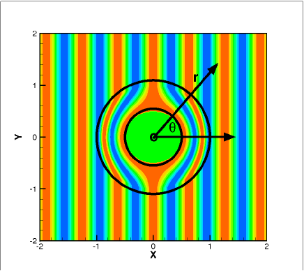
where is sound pressure; is the associated particle velocity; is anisotropic fluid bulk modulus relative to ; is anisotropic cloak density relative to fluid density ; and are normalized to unity. For simplicity, the discussion in the following is focused on circular cloaked shell in 2D polar () coordinates (as shown in Fig. 1). The outer shell radius is and inner radius is , which is nil in the transformed virtual region for a perfect 2D acoustic cloak. In other words, the transformation for an ideal cloak maps the physical region () to the virtual region (). In the physical region, the cloak density is a second order tenser, that is, . The relative anisotropic density and bulk modulus are Cummer and Schurig (2007)
| (3) |
Outside a cloak, , and are unity. It is easy to see that the above design is impractical as will go infinity as approaches . To avoid this potential singularity, the physical region () can be mapped to a virtual region (, ) by a linear transformation . Accordingly, Norris Norris (2008) recently developed generic material specifications,
| (4) |
where , and for 2D cases; for 3D cases.
From Eqs. (1)-(2) it can be seen that harmonic acoustic pressure () inside acoustic cloak is governed by the following wave equation
| (5) |
where is the normalized wavenumber. In 2D polar coordinates, this wave equation has the following form,
| (6) |
Adopting the method of separation of variables, we let and set as harmonic function, , where is an integer. Hence, satisfies the following ordinary differential equation,
| (7) |
From Eq. (4) we have and for 2D cases, Eq. (7) becomes
| (8) |
It is thus easy to find that the solution of Eq. (8) has the form: , where is the th order Bessel function of the first kind, is the th order Bessel function of the third kind, and and are parameters to be determined. As a consequence, the sound pressure in an acoustic cloak is
| (9) |
Taking into account Sommerfeld radiation condition, the series forms of sound solutions in other regions are
| (10) |
where is incident sound pressure, is sound pressure scattered from an acoustic cloak, and is sound pressure in the interior of the cloaked hollow region.
The normal velocities can be derived using Eq. (2), which yields
| (11) |
where ′ stands for and for 2D cases. Sound pressure and normal velocity should be continuous at cloak interfaces, that is, and in the physical region. We can therefore have the following relations,
| (12) |
which yield
| (13) |
where the following formulas are used,
| (14) |
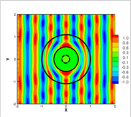
A 2D plane, progressive, harmonic wave can be described by , which equals , that is, . Hence, the corresponding in Eq. (LABEL:e:wavs) is for plane wave case. Figure 1 shows a plane wave sound pressure field calculated from above series solutions. The 2D plane wave is incident from the left onto an acoustic cloak with and . The normalized wavenumber is 10. For a perfect cloaking design, where , no reflection can be observed in Fig. 1(a). Since a perfect cloak design is difficult to implement, is adopted in practical implementations. For example, is represented in Fig. 1(b) by the dashed circle. However, scattering due to imperfect cloak design is now clearly visible in Fig. 1(b).
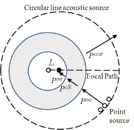
It is of interest to study the scattering patterns if a circular sound wave is incident on an imperfect acoustic cloak. Figure 2 shows the setup of the problem. The circular wave incident on a cloak is generated by an annular line sound source, which presumably consists of numerous point sources obeying a uniform distribution. The radius of the annular line source is , which is set to 3 in the following demonstration. The distance between the origin of the cloaked hollow region and the expected focal point of wavefront is . The 2D annular line source gives
| (15) |
that is, for the circular wave case. Without the presence of an cloak, the origin of the line source will be the focal point of wavefronts. In the following demonstrations, we slightly move the focal point along the focal path in Fig. 2. Practical implementation can be realized by marrying the concept of beamforming (in array signal processing) Bai and Huang (2011); Huang et al. (2012) with harmonic analysis introduced in this Letter.
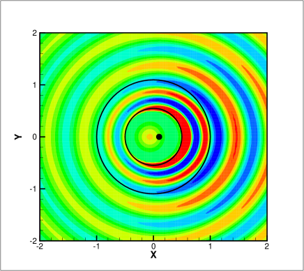
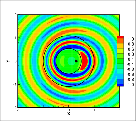
In our demonstration, Eqs. (9)-(LABEL:e:rel) can be used to calculate sound propagation and reflection. Figure 3 shows sound reflections due to circular waves with and , respectively. It can be seen that sound reflections are symmetric with respect to the -axis. The resultant scattering patterns are quite different than plane wave cases. In addition, distinctive scattering patterns appear if the focal point of circular wavefront is modified. When , the directivity of sound reflections are approximately in the direction. When , sound reflections move around the direction. For imperfect cloak cases in Fig. 1(b), it can be seen that almost no sound energy reaches the interior region. In contrast, it appears that a small fraction of sound energy arrives the cloaked hollow region. More details of sound transmission and reflections can be found in the online supplementary materials (including animations of plane wave and circular wave cases). It is for this reason that our work might find applications in imperfect acoustic cloak detection.
In summary, the method proposed in this Letter permits a purely analytical design of acoustic cloak detection strategy. Using 2D harmonic analysis, our study demonstrates unique scattering pattern due to incident circular waves generated by an annular line source. We have also developed 3D formulations, which are omitted here for brevity. In this work we conducted 2D simulations using the proposed analytical formulations at various and and similar conclusions can be drawn. It is worthwhile to note that the series solution works to any wavelength condition. Hence, we conclude that an annular line source might be useful in detecting Zhang et al. (2010) an enclosed imperfect acoustic cloak, which should have a significant impact on acoustic cloak design and defense.
The preparation of this Letter is partially supported by the NSF Grant of China (Grant Nos. 11172007 and 11110072) and SRF for ROCS, SEM.
References
- Cummer et al. (2008) S. A. Cummer, B.-I. Popa, D. Schurig, D. R. Smith, J. Pendry, M. Rahm, and A. Starr, Phys. Rev. Lett., 100, 024301 (2008).
- Chen and Chan (2007) H. Chen and C. T. Chan, Appl. Phys. Lett., 91, 183518 (2007).
- Cummer and Schurig (2007) S. A. Cummer and D. Schurig, New J. Phys., 9, 1 (2007).
- Hetmaniuk and Liu (2008) U. Hetmaniuk and H. Liu, SIAM J. Appl. Math., 70, 2996 (2008).
- Pendry et al. (2006) J. B. Pendry, D. Schurig, and D. R. Smith, Science, 312, 1780 (2006).
- Schurig et al. (2006) D. Schurig, J. J. Mock, B. J. Justice, S. A. Cummer, J. B. Pendry, A. F. Starr, and D. R. Smith, Science, 314, 977 (2006).
- Chen et al. (2007) H. Chen, B.-I. Wu, B. Zhang, and J. A. Kong, Phys. Rev. Lett., 99, 063903 (2007).
- Farhat et al. (2008) M. Farhat, S. Enoch, S. Guenneau, and A. B. Movchan, Phys. Rev. Lett., 101, 134501 (2008).
- Popa et al. (2011) B.-I. Popa, L. Zigoneanu, and S. A. Cummer, Phys. Rev. Lett., 106, 253901 (2011).
- Zhang et al. (2011) S. Zhang, C. Xia, and N. Fang, Phys. Rev. Lett., 106, 024301 (2011).
- Park et al. (2011) C. M. Park, J. J. Park, S. H. Lee, Y. M. Seo, C. K. Kim, and S. H. Lee, Phys. Rev. Lett., 107, 194301 (2011).
- Norris (2008) A. N. Norris, Proc. R. Soc. A, 464 (2008).
- Bai and Huang (2011) L. Bai and X. Huang, J. Acoust. Soc. Am., 130, 3803 (2011).
- Huang et al. (2012) X. Huang, L. Bai, I. Vinogradov, and E. Peers, J. Acoust. Soc. Am., 131, 2152 (2012).
- Zhang et al. (2010) B. Zhang, T. Chan, and B.-I. Wu, Phys. Rev. Lett., 104, 233903 (2010).