Sensors and Actuators for the Advanced LIGO Mirror Suspensions
Abstract
We have developed, produced and characterised integrated sensors, actuators and the related read-out and drive electronics that will be used for the control of the Advanced LIGO suspensions. The overall system consists of the BOSEMs (displacement sensor with integrated electro-magnetic actuator), the satellite boxes (BOSEM readout and interface electronics) and six different types of coil-driver units. In this paper we present the design of this read-out and control system, we discuss the related performance relevant for the Advanced LIGO suspensions, and we report on the experimental activity finalised at the production of the instruments for the Advanced LIGO detectors.
pacs:
04.30.-w, 07.10.Fq, 42.81.Pa, 07.50.-e1 Introduction
The first generation of ground-based gravitational wave interferometers like LIGO, GEO 600 and VIRGO [1, 2, 3] have reached their design sensitivities and are currently in the process of being upgraded to second generation - ‘advanced’ - facilities [4, 5, 6]. The planned modifications aim to widen the sensitivity band of the observatories and increase their detection range: in the particular case of Advanced LIGO [4], the upgrade will improve the detector’s sensitivity by about an order of magnitude over almost all the sensitive band, for a best strain sensitivity goal of about Hz-1/2 around few hundred Hz, and an explorable region of the universe thousand times larger.
Among the different core subsystems of the interferometer undergoing a major upgrade in Advanced LIGO, a crucial role will be played by the combined effect of an enhanced seismic isolation system [7] together with a novel multi-stage mirror suspension design [8]. This will provide an improved isolation from seismic disturbances by at least three orders of magnitude in the 1 Hz to 10 Hz region. The reduced residual motion of the test-masses - approximately m Hz-1/2 at 10 Hz - will extend the useful window for detection of gravitational wave signals from the original Hz down to 10 Hz, making background Newtonian noise and Brownian noise of the last stage of the mirror suspensions the ultimate noise sources at low frequencies [9].
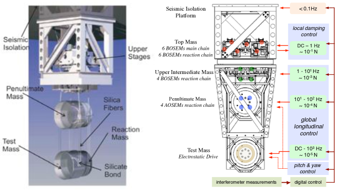
A picture of the quadruple pendulum suspension system, which is used for the isolation of the arm cavities test-masses, is shown in Fig. 1 (left). Here the key elements are the three stages of cantilever spring-blades, which form the upper-half of the suspension chain and which provide enhanced vertical-motion seismic isolation, and the 40 kg fused silica test-mass, monolithically suspended from the ‘twin’ penultimate mass by means of silicate-bonded fused silica fibres, for a ultra-low suspension thermal noise. The four-stage pendulum hangs from the ‘support structure’, which connects it to the seismic isolation platform and which is used to host the sensors and actuators used for the damping of the suspension resonances. Alongside the main suspension chain, ‘reaction-masses’ are independently suspended in parallel to the main chain and provide a seismically quiet platform for mounting the sensors and the actuators that, in combination with the ones acting from the support structure, allow for control of the arm-lengths of the interferometer.
The Advanced LIGO-UK collaboration (Science and Technology Facilities Council, University of Glasgow, University of Birmingham and University of Strathclyde) has developed the concept and the design, and has played a leading role in providing the novel and improved technologies needed for the Advanced LIGO suspension subsystem [10]. Within this collaborative effort, the Birmingham group has been responsible for the design, prototyping and development of an integrated system of sensors, actuators and analogue electronics for the dynamic control of the suspensions, and for the subsequent large-scale production of such devices. A significant fraction of the production work has been in the testing, characterisation and validation of each of the units, to ensure that the functional and scientific requirements of the instruments are met. In this paper we overview the role of this sensing and actuation system within the Advanced LIGO suspensions, we present the design and performance of such instruments and we discuss the results of experiments undertaken at the University of Birmingham for their production and validation.
2 Sensors and Actuators for the Advanced LIGO suspensions
The integrated system of sensors and actuators developed for the control of the Advanced LIGO suspension stages consists of three types of instruments:
-
•
BOSEMs (‘Birmingham Optical Sensor and Electro-Magnetic actuator’), integrated optical position sensor and electro-magnetic actuator;
-
•
Satellite boxes, electronic interfaces for the BOSEM displacement sensor;
-
•
Coil-driver units, electric current drivers for the BOSEM actuator.
The working principle of the integrated BOSEM read-out and actuation system is described with the diagram in Fig. 2.
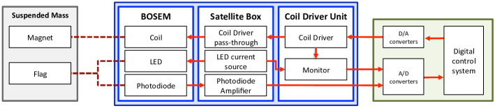
The motion of the suspended mass is sensed by the BOSEM, whose signal is filtered and amplified by the satellite box, and sent to the main digital control system. Here the signal is processed and purposely optimised to be then fed back through the coil-driver amplifier to the BOSEM coil, to eventually actuating on the suspended masses. Within the Advanced LIGO suspensions, this system is used to monitor and control the suspension stages during the initial alignment, damping and acquisition of the different interferometer subsystems, and subsequently to support, in combination with the interferometric measurements, the control of the position of the suspended optics to allow for quiet operation of the interferometer science mode.
A sketch of the Advanced LIGO quadruple suspension’s control loop scheme, showing the role of the instrumentation discussed in this paper, is given in Fig. 1 (right) and in Fig. 3. The BOSEM’s system provides optical sensing and electro-magnetic actuation capabilities in the three top stages. Six units are used to provide sensing and control on all six d.o.f of the top-masses of the main suspension chain, and other six are similarly employed for the reaction chain; four BOSEMs units control the swing, pitch and yaw modes of the main chain second stage, acting from the reaction one; due to the reduced actuation forces required to actuate on the penultimate suspension stage, satellite boxes and coil-drivers are here integrated with a similar but compact and lightweight sensing and actuation instrument, the re-engineered version of Initial LIGO OSEMs [11] now dubbed AOSEMs [12]; finally the smaller amplitude, higher frequency actuation forces required to control the mirror test-masses, on the fourth and bottom stage, are provided electro-statically with a different type of instrument, named the Electrostatic Drive [13].
The integrated BOSEMs system allows sensing of the motion of the suspended masses with displacement sensitivities of the order of m Hz-1/2 or better in the frequency range from 0.1 Hz up to 10 Hz and above, and provides at the same time strong actuation authority on the masses with overall force peaks of order hundreds mN on each d.o.f. and damping times of order 10 s combined with very low actuation force noise, at the pN Hz-1/2 level and below. With the four pendulum stages naturally suppressing the residual longitudinal motion of the lowest mass by about seven orders of magnitude (from Hz), the BOSEMs sensitivity allows initial damping of the test mass motion down to a level of m Hz-1/2, at frequencies around few Hz and above. The seismic isolation goal, namely m Hz-1/2 at 10 Hz, is then achieved combining the BOSEM system with interferometer and cavity signals - with sensitivity well below the pm Hz-1/2 level [8] - and with the electrostatic drive actuation - with residual forces at fN Hz-1/2 level or better - and by making use of sophisticated damping and control algorythms, see for example [14, 15].
Compared to different typologies of displacement sensors used in other GW detectors 888It is important to note that GEO 600 used OSEM-like sensors and actuators, and that the BOSEMs presented here are now in use in the GEO 600 upgrade, GEO-HF. (e.g., accelerometers, LVDTs, CCD-camera based optical levers [16, 17]), the BOSEMs have been selected for the reduced dimensions and the higher sensitivity provided, other than of course for continuity with the Initial LIGO design. At the same time, thanks to the relaxed sensing requirements, the BOSEMs have been preferred to potentially more sensitive interferometric sensor designs, also investigated during the preliminary study phase [18], for the more mature technology and proven reliability, and for the known contained costs and relative simplicity of large scale manufacturing. Concerning the coil magnet actuation scheme, which is widely used in all other GW detector suspensions, a crucial role in the selection of the BOSEMs design was played by the compactness of the design itself, with sensing and actuation in the same device, which made them the favourable choice for the simplicity of installation, testing and eventually operation. The BOSEMs and related electronics provide a similar sensing and actuation functionality to the ‘shorter’ suspension types (‘triple’ and ‘double’ suspensions), which are used for optical elements of the interferometer demanding less stringent seismic isolation, such as for instance beam-splitters and mode-cleaner optics. The BOSEMs are here used for the upper stages, the AOSEMs for the lower ones, and satellite boxes and coil-drivers serve the sensors and actuators at all stages. In total, about 185 BOSEM actuation units are employed for local and global control of each Advanced LIGO interferometer. The overall production run at Birmingham delivered to Advanced LIGO consists of 650 BOSEMs, 230 satellite boxes, and 267 Coil Driver units for the three Advanced LIGO interferometers. This includes about 25% spare units produced for redundancy and replacement in the event of device failure, and about 100 units for the interferometer prototypes.
2.1 BOSEM
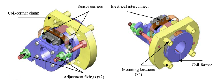
The BOSEMs are compact, ultra-high-vacuum (UHV) compatible, non-contact, low-noise position sensors with integrated electro-magnetic actuator. The BOSEMs working principle is based on the original concept by Shoemaker et al [19], and their final design builds upon a series of incremental modifications to the Initial LIGO OSEM and on the subsequent sensor study and optimisation process described in [20, 21, 22, 23, 24]. Each unit comprises several interconnected subsystems: optical read-out; coil-magnet actuator; magnet-flag assembly; alignment system; electrical connection. CAD models of the BOSEMs assembly are shown in Fig. 4, while a sketch of the integrated subsystems is given in Fig. 5 (left).
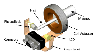
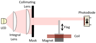
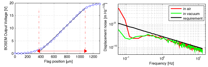
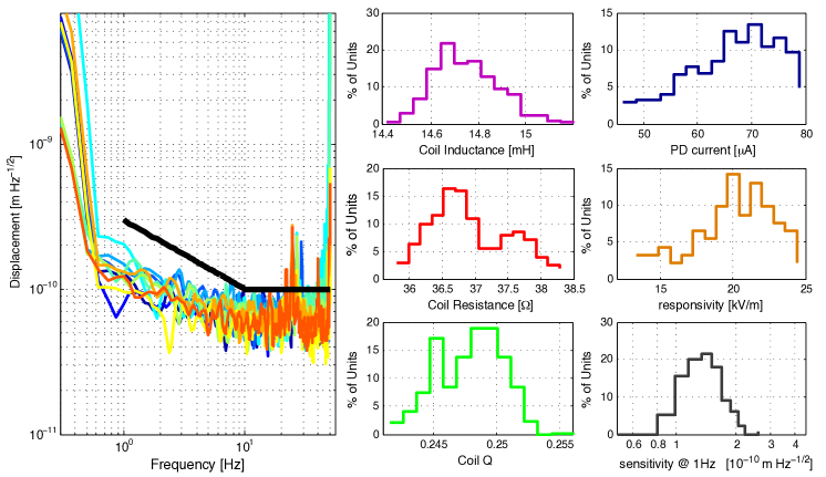
The optical read-out works following the shadow-sensing detection scheme depicted in Fig. 5 (right): an opaque object (‘flag’) is used to obscure a fraction of the light cast by a LED onto a single quadrant photodiode (PD), generating a current in the PD which is related to the position of the flag. A set of lenses and a mask are also included to improve the collimation of the beam emitted from the LED. This ensures that only paraxial rays hit the PD sensing area, improving linearity and reducing noise. The flag is a 25 mm3 mm Al cylinder, which moves along its longitudinal axis. The shape and size of the flag were chosen after investigating a range of possible geometries [24] 222More recent developments emerged during commissioning of the suspensions have suggested a small modification in the design, with a reduced flag thickness and flattened sides along the non-measurement axis to further facilitating the installation process, and a wider flag size in the orthogonal direction to decrease sensing cross-coupling [25].. The BOSEMs use commercial infra-red opto-electronic components (Vishay TSTS7100 LEDs, BPX65 PDs) with emission and detection peaks around 950 nm and negligible emission at the main interferometer wavelength (1064 nm). The LED is operated at about 15% of its maximum radiant power (10 mW), which combined with the PD output (0.55 A/W) results in a mean photocurrent at the PD output of A, when the flag is in half-light position (i.e., PD sensing area obscured by 50%). The measuring range of the optical sensor is about 700 m, determined by the dimensions of the PD sensing area. The average responsivity, when measured with the accompanying satellite box amplifier, ranges around R 20 kV m-1, as shown in Fig. 6 (left). The ultimate limit to the BOSEM read-out sensitivity is set by photo-current shot-noise in the PD, and it can be expressed as , with is the electron charge and k is the resistance of the trans-impedance amplifier at the output of the PD, resulting in an ultimate displacement sensitivity about m Hz-1/2. The measured BOSEM sensitivity, as shown in Fig. 6 (right) and Fig. 7 (left) in comparison with the Advanced LIGO requirement, is typically limited by photo-current shot-noise in the PD at frequencies above 10 Hz, and by 1/f photo-current noise in the LED at lower frequencies.
To actuate on the suspended test masses, the BOSEM incorporates a magnet which is rigidly mounted with the flag and it is concentrical to a coil purposely driven by the coil-drivers (see Fig. 5). To cater for the large weight of the suspended masses, the BOSEMs provide peak actuation forces up to about hundred mN per actuator, about one order of magnitude enhancement with respect to the Initial LIGO OSEM. This is achieved with a modified coil design (800 turns of polyimide coated 32-AWG wire) and with 10 mm10 mm Nd-B-Fe cylindrical magnets (magnetic moment Am2) 333Due to the relaxed actuation strength requirements, on intermediate and penultimate stages the BOSEMs use SmCo magnets and different size and magnetic moments [28]. [26, 27, 28]. Residual magnetic forces are kept below 5mN, by use of low magnetic susceptibility Al6082 for the mechanical parts, and with a proper separation of actuator and sensor parts. Furthermore, the BOSEM magnets are assembled in quadrupolar configuration on the test masses in order to null the resulting overall magnetic moment and thus minimise their susceptibility to external magnetic fields. The electromagnetic cross-talk from the actuation coil to the readout channel was measured to be below m/A and it was found to be most prominent only at frequencies above 30 Hz, i.e. where this coupling is naturally mitigated by the mechanical transfer function of the quadruple pendulum , and to be arising from non-shielded harnesses of the test equipment to and from the Satellite Boxes (however shielding is foreseen in the final design).
The BOSEM design incorporates several other functional features which have been included to facilitate large scale production and reproducibility of the device’s performance, and to improve their usability. The overall compact design (less than mm3 volume and 170 g mass) incorporates a user-friendly mounting and alignment mechanism, which allows 10 mm longitudinal and 1.5 mm lateral adjustments with respect to the flag position, during installation process. Performance reproducibility is improved also with the use of standard-leaded components, in place of the originally glued surface-mount ones, which are press-fit into ceramic sleeves, encapsulated with retainers in aluminium alloy assemblies, and eventually screwed in to position, minimising the overall misalignment of the components. The absence of potentially outgassing adhesives from the fabrication and alignment process provides also an enhanced UHV compatibility of the assembly. Finally, the BOSEMs use flexi-circuit for interconnections to/from LED, PD and the coil, and miniature D-type connectors, to facilitate assembly/disassembly and testing of individual components.
Production of the BOSEMs was conducted in Birmingham’s clean room facilities, after fabrication of mechanical parts by external contractors, followed by in-house inspection against tolerances, and subsequent cleaning and baking according to Advanced LIGO UHV requirements. All opto-electronic components have been pre-screened to identify infant mortality of the devices and to ensure performance consistency. A more intensive pre-screening of the LEDs was necessary to avoid an observed non-reproducibility in the noise performances of the LEDs themselves, degrading the BOSEMs displacement sensitivity by about a factor two above specifications. This was eventually related to a non-reproducible deposition of the adhesive used in the LED package sealing during the manufacturing process [30] which was therefore impossible to identify via non-destructive physical inspection of the devices, and required extensive noise-characterisation of each individual LED unit, and the selection of only the compliant ones (about 75% of the total).
All assembled BOSEMs have been tested using the Automated Test Equipment - ATE, also part of the deliverables 111The BOSEM-ATE consists of an LCR Meter, Digital Multimeter, USB interface box, and software to run the tests and store the data on a PC. - to ensure consistency across the entire batch, reject non-compliant units and to provide a fully trackable record of the relevant properties (coil resistance, inductance and electrical , PD current). About 20% of all the delivered BOSEM units underwent full end-to-end characterisation test using Advanced LIGO representative equipment, providing a complete record of operating range, responsivity, and displacement sensitivity [31]. Examples of the results from this characterisation campaign, and some statistics on the reproducibility of the production articles performances are shown in Fig. 7.
2.2 Satellite boxes
The ‘satellite boxes’ incorporate a current supply for the BOSEM LEDs, a voltage amplifier for the BOSEM PD signal, and provide electrical pass-through from actuation electronic units to the coils. Monitoring circuits are also included in the unit to monitor its activity and status. Each satellite box is equipped with four current sources and amplifier channels, serving four OSEMs units at a time.
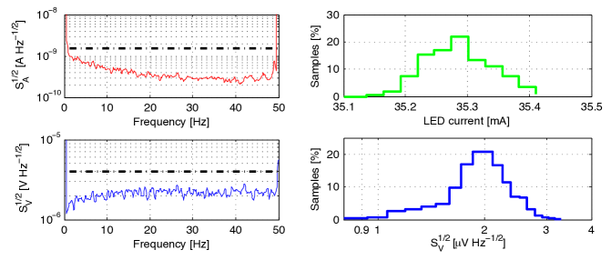
The current source generates a stable, low noise current with nominally 35 mA and a measured noise level of nA Hz-1/2 at 10 Hz, which corresponds to an equivalent displacement noise of m Hz-1/2, three times lower than the requirement [32]. The PD amplifier converts the PD current output into a -/+10 V signal, with intrinsic voltage noise not exceeding the 4 V Hz-1/2 upper limit requirement [33] and equivalent to a displacement noise of m Hz-1/2 at 10 Hz.
Satellite box manufacturing was conducted by outsourcing the production of PCBs to external contractors, and consequently populating and assembling the units in-house. Functional and performance testing has been performed on all the production articles with a dedicated ATE, and recorded for performance traceability [31]. The characteristic LED current noise, the PD amplifier voltage noise and some statistics on reproducibility of the performances of the satellite box production units are presented in Fig. 8.
2.3 Coil-driver units
The ‘coil-driver’ units [31] amplify the signal from the digital control system to drive the BOSEMs coils for actuating on the suspension stages. Each coil-driver unit contains four current drive circuits, and is equipped with read-back circuitry for remote monitoring of the unit performance.
| Coil-driver | Q-TOP | UIM | PUM | ||||||
|---|---|---|---|---|---|---|---|---|---|
| dynamic range |
|
|
|
||||||
| noise @ 1 Hz | 1 nA Hz-1/2 | 0.5 nA Hz-1/2 | 20 nA Hz-1/2 | ||||||
| noise @ 10 Hz | 73 pA Hz-1/2 | 3 pA Hz-1/2 | 4 pA Hz-1/2 | ||||||
| noise @ 100 Hz | 1000 nA Hz-1/2 | 200 nA Hz-1/2 | 5 nA Hz-1/2 | ||||||
| noise @ 1000 Hz | 1000 nA Hz-1/2 | 1000 nA Hz-1/2 | 1000 nA Hz-1/2 | ||||||
| actuation strength | 1.7 N A-1 | 1.7 N A-1 | 0.03 N A-1 | ||||||
| max force noise @ 10 Hz | 40 pN Hz-1/2 | 8 pN Hz-1/2 | 0.1 pN Hz-1/2 |
Within the Advanced LIGO suspensions, the coil-driver units serve two functions: first, to provide strong actuation authority for the damping of the motion of the suspended masses, to allow for acquisition of the interferometer system; second, to provide quiet actuation to allow for control of the overall interferometer during detector science mode.
Six different types of coil-drivers have been developed, each designed for the specific performance, in terms of frequency response, output current and noise levels, each stage and type of the suspension required. The coil-drivers actuation functions are mainly three: ‘top’ coil-drivers serve for the static alignment/positioning of the optics and correction of slow drifts, and more generally compensate for the very low frequency motion of the optics below 1 Hz; ‘intermediate’ coil-drivers control the low frequency suspension’s dynamics in the frequency range between 1 Hz and 10 Hz; ‘lower’ coil-drivers actuate at high frequencies (above 10 Hz) and serve for interferometer lock acquisition (‘acquisition mode’) and lock maintenance (‘run mode’). The performance requirements for each of the coil-driver units employed in the quadruple suspensions control system, named Quadruple Top (Q-TOP), Upper Intermediate (UIM) and Penultimate (PUM) is given in Table 1 [34]. Coil-drivers units designed for shorter suspension types have similar frequency dependence and slightly relaxed noise requirements [34].
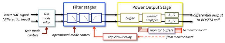
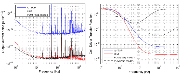
The coil-drivers are designed to generate low noise, high drive currents based on the input signals of up to 20 Vpp and with a maximum input noise of nV Hz-1/2, coming from the digital control system. A sketch of the coil driver’s working principle is shown in Fig. 9. The large dynamic range of the output current (up to 180 dB as shown in Table 1) is necessary to combine the diverse functionalities required for the BOSEM coil actuation system discussed above. To provide the demanded high current at the output, the input signals are buffered with high-power operational amplifiers. The maximum values for the output current are set using suitable output impedances in series with the BOSEM coil resistance . The output current noise is determined by the input voltage noise from the digital control system and by the intrinsic voltage noise generated inside the coil-driver circuitry, and it can be expressed as , with the coil-driver transfer function. On one hand, is kept low with purposeful design of the circuitry itself, careful selection of the active components and suitable rejection of external noise, mainly due to electrical ground instability. On the other, the different filtering stages included in the units provide the requested transfer functions to reduce the role of the input noise down to a negligible level. Measurements of the typical performance of the coil-driver units used in the quadruple suspensions are presented in Fig. 10, and show how these units agree with specifications over the entire bandwidth.
As well as meeting the technical specifications discussed above, the coil-drivers were designed to comply with several additional operational requirements. Besides having a robust and reliable design that could guarantee a long operational life-cycle, a relatively large adaptability of the units was specifically requested, in particular to permit for later optimisations to the frequency responses of the coil-driver units as the understanding of the overall system is expected to develop with the commissioning and operation of Advanced LIGO. This was implemented by making the filter sections switchable by means of relays, chosen for their inherently lower noise. Similarly, the different operational modes, e.g., ‘acquisition’ or ’run’ mode of the lower stages coil-driver units, are implemented with relays switching between different output resistors and filters. Furthermore, to provide serviceability and ease of modification the electronic layout was intentionally non-extensively miniaturised and the PCBs were populated at low density, to facilitate a rapid replacement of a potentially failing component, or to enable components to be added or their values changed.
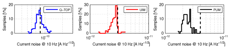
The coil-driver units represent a large proportion of the articles produced at the University of Birmingham for the Advanced LIGO suspensions, for a total of about 270 units. As for the satellite boxes, coil-driver PCBs were designed in-house, manufactured by external contractors, and then assembled, tested and characterised in Birmingham. For all the coil-driver production units, all performance and functional requirements have been individually tested, validated and the results recorded for future reference [31]. Statistics on some of the output current noise performance of the quadruple suspensions units are shown in Fig. 11 in comparison with the respective requirement.
3 Conclusion
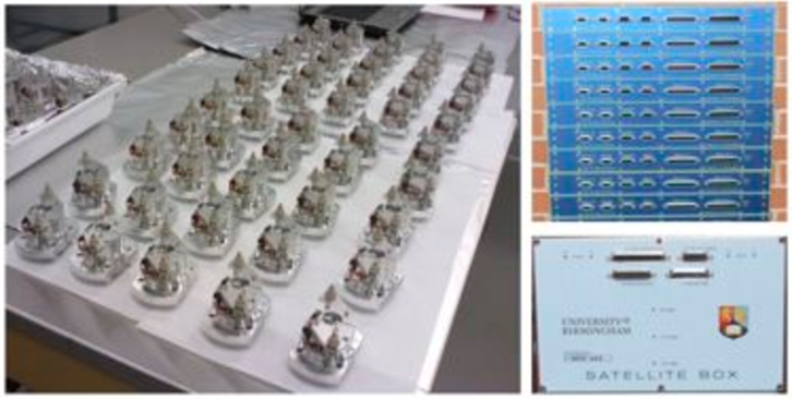
Production and testing of the instrumentation discussed in the previous sections, and here shown in the photographs in Fig. 12, was completed by the end of the Advanced LIGO UK project grant, which formally terminated in March 2011. All the produced instruments were successfully characterised and their performance validated to meet the stringent requirements for the achievement of the seismic isolation goals of the Advanced LIGO suspensions. All items were shipped overseas to their destination at the Advanced LIGO detector sites (1/3 of the production units to the Livingston Laboratory, 2/3 to Hanford) as well as to the prototypes. The instruments are currently being installed and commissioned on the different interferometer suspensions systems, and preliminary performance of the system is successful and encouraging for the future sensitivity of Advanced LIGO.
The sensing and actuation technology presented in this paper has been successfully pushed very far in all aspects of the required performance, and further improvements are likely to demand substantial re-design effort. With this aim, further R&D work is underway to investigate improved solutions for sensing and actuation instrumentation for a potential employment in future GW detectors of the third generation.
References
References
- [1] B.P. Abbott et al 2009 Rep. Prog. Phys. 72 076901, http://www.ligo.org/
- [2] S. Hild et al, Class. Quantum Grav., 23, S643, 2006, http://www.geo600.org
- [3] F. Acernese et al, Class. Quantum Grav., 25, 2008, http://www.ego-gw.it/
- [4] G.M. Harry and the LIGO Scientific Collaboration, Class. Quantum Grav. 27 084006, 2010.
- [5] B. Willke et al, Class. Quantum Grav., 23, S207, 2006
- [6] T. Accadia et al, Class. Quantum Grav. 28, 114002, 2011
- [7] R. Abbott et al, Class. Quantum Grav. 21 S915, 2004
- [8] N. Robertson et al, Class. Quantum Grav. 19 (2002) 4043-4058
- [9] A. Cumming et al, Class. Quantum Grav., 26, 21, 215012 (2009) and references therein
- [10] J. Greenhalgh, Advanced LIGO UK Participation, LIGO-G030424-00-K, 2003
- [11] P. Fritschel. Characterization and comparison of a potential new local sensor, LIGO-T990089-00 1999.
- [12] R. Abbott et al, Advanced LIGO OSEM Final Design Document, LIGO-T0900286-v2, 2009
- [13] N.A. Lockerbie, Electrostatic Driver, LIGO-T1100231-v2, 2011
- [14] B. Shapiro et al, Modal Damping of a Quadruple Pendulum for Advanced Gravitational Wave Detectors, 2012 American Controls Conference
- [15] K. A. Strain et al, Rev. Sci. Instrum. 83, 044501 (2012)
- [16] V. Dattilo for the VIRGO collaboration, Physics Letters A 318 (2003) 192
- [17] F. Acernese et al, Astroparticle Physics 20 (2004) 617
- [18] C.C. Speake et al, Class. Quantum Grav. 22 S296 (2005)
- [19] D. Shoemaker et al, Physical Review D 38, 2, 423 (1988)
- [20] J. Romie, Hybrid OSEM assembly specification, LIGO-E030084-02-D, 2003
- [21] K.A. Strain et al, Recommendation of a design for OSEM sensors, LIGO- E040108-01-K, 2004
- [22] K.A. Strain, Input to the OSEM selection review decision, LIGO- T040110-01-K, 2004.
- [23] N.A. Lockerbie, Measurement of LIGO hybrid OSEM sensitivity LIGO-T040106-01-K, 2004.
- [24] N.A. Lockerbie, Measurement of shadow-sensor displacement sensitivities LIGO-T040136-00-K, 2004.
- [25] M. Evans, BOSEM Flat Magnet Flag, aLIGO SUS, LIGO-D1100573-v5, 2011
- [26] K.A. Strain, Advanced LIGO suspension: summary noise calculations as input to the UK electronics PDR. LIGO-T050122-00-K, 2005
- [27] K.A. Strain, Increased strength Advanced LIGO ITM/ETM suspension PM and UIM Actuators, LIGO-T060001-00-K, 2006
- [28] N. Robertson et al, Magnet sizes and types and OSEM types in Adv. LIGO suspensions, LIGO- M0900034-v4, 2011
- [29] S.M. Aston, BOSEM Design Document & Test Report, LIGO-T050111-04-K, 2009
- [30] S.M. Aston, Optical Read-out Techniques for the Control of Test-masses in Gravitational Wave Observatories, PhD Thesis, University of Birmingham, 2011.
- [31] L. Carbone et al, Summary of technical documentation for University of Birmingham deliverables, LIGO-T1100185-v2, 2011, and references therein,
- [32] L. Carbone et al, Satellite Boxes Current-Source noise characterisation, LIGO-T1000630-v2, 2010.
- [33] D. Hoyland et al, OSEM Drive Electronics Interface Control Document, LIGO-E040374-00-K, 2004
- [34] J. Heefner, AdL Quad Suspension UK Coil-Driver Design Requirements, LIGO-T060067-00-C (2006); J. Heefner, AdL Beam Splitter, Input Mode Cleaner, Large Recycling and Small Recycling Triple Suspension Electronics Requirements, LIGO-T080065-E1-C (2008); info also available at www.its.caltech.edu/rana/aLIGO/suselecreq.html
- [35] M. Barton, Calculation and measurement of the OSEM actuator sweet spot position, LIGO-T1000164-v3, 2010