The KLOE-2 High Energy Tagger Detector
Abstract
In order to fully reconstruct to the reaction in the energy region of the meson production, new detectors along the (DANE) beam line have to be installed in order to detect the scattered . The High Energy Tagger (HET) detector measures the deviation of leptons from their main orbit by determining their position and timing so to tag physics events and disentangle them from background. The HET detectors are placed at the exit of the DANE dipole magnets, 11 m away from the IP, both on positron and electron lines. The HET sensitive area is made up of a set of 28 plastic scintillators. A dedicated DAQ electronics board based on a Xilinx Virtex-5 FPGA have been developed for this detector. It provides a MultiHit TDC with a time resolution of the order of 500 ps and the possibility to acquire data any 2.5 ns, thus allowing to clearly identify the correct bunch crossing. First results of the commissioning run are presented.
keywords:
Tracking detectors1 HET Detector
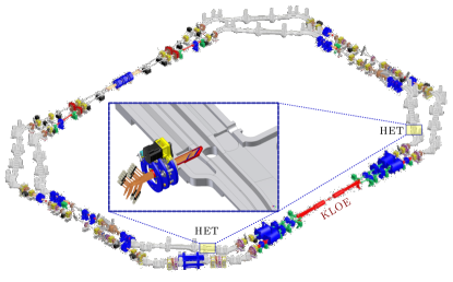
The High Energy Tagger (HET) detector now installed in KLOE-2 [1] is a position detector used for measuring the deviation of leptons from their main orbit in DANE. By means of this measurement and of its timing, we are able to disentangle, and therefore to tag physics [2] events. Two HET detectors are placed at the exit of the dipole magnets (see Fig. 1), 11 m away from the IP, both on positron and electron arm. The sensitive area of the HET detector is made up of a set of 28 plastic scintillators. The dimensions of each of them are . One additional scintillator, of dimensions: is used for coincidence purposes. The light emitted by each of the 28 scintillators is read out through a plastic light guide by a photomultiplier. The 28 scintillators are placed at different distances from the beam-line, in such a way that the measurement of the distance, between the hitting particle and the beam, can be performed simply knowing which scintillator has been fired.
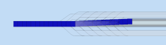
On the vertical plane (see Fig. 2), the scintillators are aligned, with the exception of a slight curvature at big distance from the beam, this is due to maximize the HET efficiency due to the KLOE magnetic axial field and DANE compensator. They show their face to the impinging particles that go through them along the thickness of 3 mm. The scintillators are not placed side by side, on the contrary there is an overlap of 0.5 mm on the 5 mm side.
The plastic scintillator used is the EJ-228 premium plastic scintillator produced by Eljen Technology. It is intended for use in ultra-fast timing and ultra-fast counting applications and it is recommended for use in small sizes (any dimension less than 100 mm). The EJ-228 scintillator is composed of Polyvinyltoluene and has a density of 1.023 g/cm3 and a refractive index of 1.58 and a light output 67 of anthracene, the emission spectra is peaked around 391 nm.
Because of the small dimensions of the scintillator in use, the total light yield, due to a crossing electron or positron, is quite small. For this reason, we chose a high quantum efficiency photomultiplier to minimize the probability of a particle, which crosses the scintillator, to go undetected. The photomultipliers used are compact size and high quantum efficiency ones, model R9880U-110 SEL produced by Hamamatsu Photonics. The quantum efficiency is about 35% for a wavelength going in the range from 300 nm to 400 nm, well matching the EJ-228 emission.
2 HET Electronics
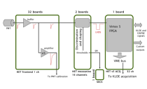
The HET acquisition system is composed of a set of three electronic boards, and one slow control board (see the scheme in Fig. 3). The first part of the chain, handling PMT analogue signals, is called the front-end electronics and is composed of the HET front-end board and the discrimination and shaping board. The second part, which performs the measurements and interact with signals from KLOE and DANE, is called HET acquisition system and is composed of the HET data acquisition board.
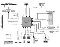
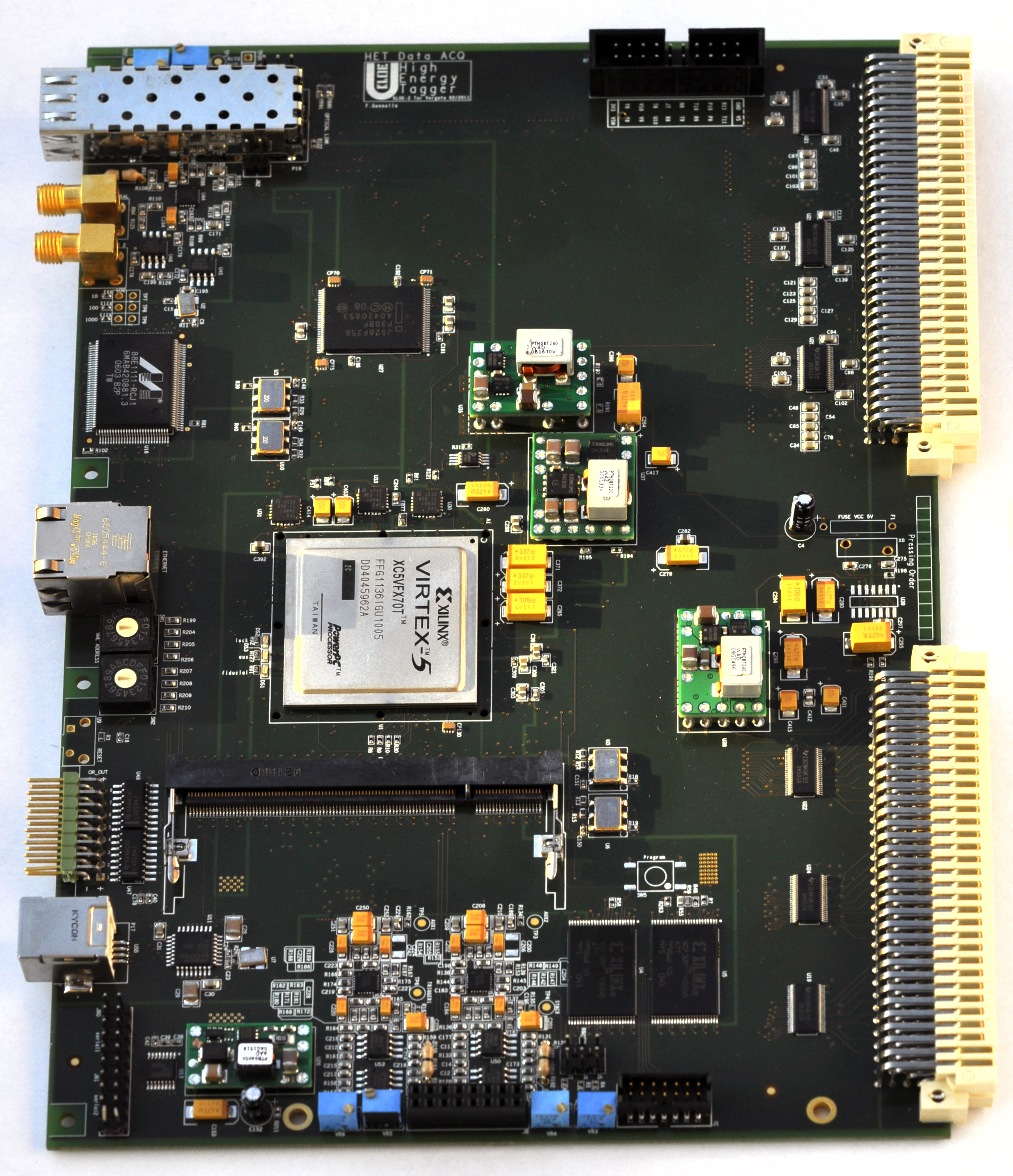
The HET main acquisition is a VME 6U board. The tasks handled by this board are to measure the timing of the signals coming from discriminators with respect to DANE fiducial signal, store them only if KLOE trigger are asserted, and transmit data to the KLOE acquisition system through the VME bus. To this end, this board is equipped with:
-
1.
Xilinx Virtex 5 FPGA, in which the TDC, the HET DAQ system and the VME interface are implemented;
-
2.
6 inputs and outputs to handle DANE fiducial signal and the KLOE trigger signals;
-
3.
32 LVDS input channels for the TDC;
-
4.
fast VME transceivers;.
The Virtex 5 XC5VFX70T is the main component of the board, handling all the on-board devices (see Fig. 4 and 5).
3 First Results
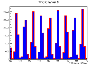
Both electron and positron arms detectors are now installed and in the commission phase. Since the bunch crossing occurs in DANE each 2.7 ns, in order to properly disentangle leptons coming from two consecutive bunch crossings, the TDC time resolution must be less than as it is shown in Fig. (6).
References
- [1] G. Amelino-Camelia, et al., Physics with the KLOE-2 experiment at the upgraded DANE, Eur. Phys. J. C 68, (2010), 619.
- [2] D. Babusci, et al., On the possibility to measure the decay width and the transition form factor with the KLOE-2 experiment, Eur. Phys. J. C 72, (2012), 1917.