Influence of spin-flip on the performance of the spin-diode
Abstract
We study spin-dependent transport through a spin diode in the presence of spin-flip by means of reduced density matrix approach. The current polarization and the spin accumulation are computed and influence of spin-flip on the current polarization is also analyzed. Analytical relations for the current polarization and the spin accumulation are obtained as a function of polarization of ferromagnetic lead and the spin-flip rate. It is observed that the current polarization becomes zero under fast spin-flip and the spin accumulation decreases up to when the time of spin-flip is equal to the tunneling time. It is also observed that the current polarization increases linearly when the dot is singly occupied, whereas its behavior is more complicated when the dot is doubly occupied.
1 Introduction
Spin dependent transport through mesoscopic systems has been widely studied both experimentally and theoretically points of view [1, 2, 3, 4, 5]. Study of transport through quantum dots (QDs) provides worthful information about novel physical phenomena such as Kondo effect [6, 7], spin and Coulomb blockade effects [8, 9, 10, 11], tunneling magnetoresistance [12, 13, 14], etc. Coupling of the QD to different leads can result in different transport properties. Spin filters composed of normal metallic leads [15, 16] and ferromagnetic leads have been applied for producing spin accumulation affecting on negative differential resistance (NDR) [17] and zero bias anomaly [18].
An interesting structure is composed of the QD coupled to a nonmagnetic lead and a ferromagnetic lead. It has been shown that the QD can act as both a spin diode and a spin filter by reversing bias voltage [14, 17]. Diode-like behavior in a carbon nanotube coupled to a normal metal and a ferromagnetic lead was recently reported [19]. This behavior was also observed in resonance tunneling connected to ferromagnetic contacts with different spin-dependent transparencies [20]. Spin diodes have been theoretically investigated without taking into account spin-flip [21, 22]. In this paper, we analyze this structure with taking into account spin-flip process in sequential tunneling regime. Rate equations are used to describe the states inside the QD with considering coherency between different states. This subject was recently studied by C. Feng and co-workers [23]. Here, we extract analytical relations for spin current polarization and spin accumulation. We show how spin-flip decreases the current polarization and its effect on the spin accumulation is also studied. Dependence of the current polarization on the polarization of the magnetic lead is also examined.
The article is organized as follows: in the next section, we compute the spin-dependent current using rate equations. Then, the numerical results are presented and the behavior of the system is analytically studied. Finally, some sentences are given as a conclusion.
2 Description of the model
We consider a single level quantum dot coupled to a normal metal and a ferromagnetic lead. Hamiltonian describing the system is
| (1) |
where describes the leads, destroys (creates) an electron with wave vector , spin in the lead (). In continue, it is assumed that the left lead is normal metal while the right one is ferromagnetic. Hence energy of electron is spin-independent in the left lead, whereas for the right lead that is band spin splitting. where is Coulomb repulsion, and is occupation operator. denotes the annihilation (creation) operator in the QD. is the energy level of the QD. We assume that the QD is capacitively coupled to the gate (G), left and right electrodes. describes the tunneling between leads and the QD. contains spin-flip scattering inside the QD, where is spin-flip rate. This process can be obtained by, for instance, spin-orbit interaction [24] or a transverse magnetic field [15] that rotates the electron spin.
The QD can be in i) empty state , ii) singly occupied state () () or iii) doubly occupied state (). It is clear that the states and are not the eigenstates of the isolated QD because of spin-flip. In order to study the QD, reduced density matrix has been used. Using Markov approximation, time evolution of reduced density matrix elements are given as follows [25, 26] ():
| (2) | ||||
is the probability of being in the state (), whereas describes the coherency between the states and . and denotes the transition from to and is computed by means of Fermi’s golden rule as
| (3) |
where stands for the number of electrons in the state () and is the transition energy. is Fermi distribution function of the lead with chemical potential , whereas . For computing the tunneling rates (), wide band approximation is used i,.e. dot-lead coupling is energy independent and . Hence, for instance, and are obtained from eq.2 as
| (4a) | ||||
| (4b) | ||||
and it is clear that .
Solving Eqs. 2 in the steady state (), spin-dependent current crossing from the lead is computed by
| (5) |
where is the opposite of . For simulation purpose we set and where is the dot-lead coupling strength and is the spin polarization degree of the right lead. We also set and where is applied bias. Therefore, the left lead acts as an emitter when the bias is positive, while the right one acts as the emitter in negative bias.
3 Results and discussions
Fig. 1a shows the current polarization as a function of bias. As we expect, spin-flip reduces the current polarization because this process tries to destroy the spin polarity of the system. It is observed that the device can operate as a spin diode when the QD is singly occupied. In positive bias when , the current polarization becomes zero because the left lead acts as the emitter. Note that and for the left lead, we have and as a result . On the other hand, for negative bias i.e. , the current polarization is maximum because of . Indeed, a spin-up electron enters the QD faster than a spin-down electron from the right lead. Although the device acts as a spin diode in the presence of spin-flip, the current polarization reduces significantly. When the QD is singly occupied, the current polarization is given as [27]
| (6a) | ||||
| (6b) | ||||
where . It is clear from above equation (Eq. (6b)) that increasing gives rise to decreasing . Note, for , our results are the same as Eqs. 21 in the Ref. [21]. If the time of spin-flip is much shorter than the time of tunneling i.e. , the current polarization becomes zero. Indeed, spin-flip destroys the effect of the ferromagnetic lead on the QD, completely.
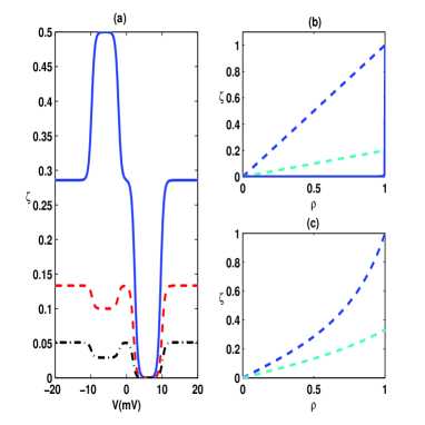
The dependence of the current polarization on the under conditions that the QD is singly occupied is plotted in the fig. (1b). In positive bias, the current polarization is always zero, except in . When the right lead is a half metal the current polarization will be equal to one because the spin-down electron injected from the left lead can not leave the QD, therefore . This behavior was reported before in the Ref. [21]. It is straightforward to show that the probability of being in the state is given as [27]:
| (7) |
It is clear from the Eq. (7) under conditions that , the QD is occupied by a spin-down electron. In the presence of spin-flip, this electron can change to a spin-up electron. More specifically, if spin-flip occurs fast enough (), we have . As a consequence, the current polarization is zero under fast spin-flip even though the right lead is a half metal. In negative bias, the current polarization increases linearly, as we expect from Eq. 5b. Increasing means that the spin-up electron enters the QD faster and ,hence . The dependence of the current polarization on the when the QD is doubly occupied is plotted in the fig. 1c. It is observed that the current polarization is the same for both positive and negative biases. It can be shown that in high bias regime [28], the current polarization is
| (8) |
It is observed that when and , the current polarization approaches .
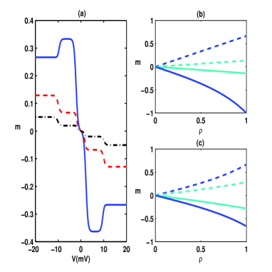
The spin accumulation () is shown in the fig. 2a. In positive bias, the spin accumulation is negative because the spin-up electron injected from the left lead leaves the QD faster and, hence . In negative bias, the right lead operates as the emitter so that the spin-up electron enters the QD faster and as a result the spin accumulation becomes positive. Spin-flip scattering reduces the spin accumulation significantly. In the presence of spin-flip, it is probable that the electron in the QD rotates. This rotation leads to the reduction of the spin accumulation. There are tow plateaus in each side of the figure. The first one is due to entering inside the bias window whereas the next one is created when takes place inside the bias window.
The dependence of the spin accumulation on the is plotted in the figs. 2a and 2b. It is observed that when the QD is singly occupied and the right lead is a half metal, the spin accumulation will be equal to if no spin-flip is considered. This behavior was predictable from Eq. (7). If the spin-flip rate is equal to , the spin accumulation decreases up to . Unlike positive bias, the spin accumulation increases linearly in terms of in negative bias. It can be shown that in single electron state is given by
| (9a) | ||||
| (9b) | ||||
It is interesting to note that in positive bias, even though it is assumed that the right lead is a half metal and no spin flip is considered, is always lesser than . It results from this fact that the probability of finding the QD in the empty state is equal to . Indeed, the probability of being in the state is given as:
| (10) |
It is clear from above equation that if we set and , will be 2/3. The magnitude of is the same for both positive and negative bias when the QD is doubly occupied. In this situation, one can obtain [28]
| (11) |
where the minus sign is for positive bias and plus sign is for negative bias. It is also found that is always lesser that because of interplay between spin accumulation and Coulomb interaction.
4 Conclusion
In this article, we analyze spin current polarization through a QD coupled to a normal metal and a ferromagnetic lead by means of rate equations in the presence of spin-flip scattering. It is observed when an energy level of the QD is inside the bias window, this system can operate as a rectifier for spin current polarization and show how spin-flip can decrease the magnitude of the polarization. It is observed that the spin accumulation and the current polarization decrease significantly when spin-flip occurs faster than the tunneling event. Dependence of the current polarization and the spin accumulation on the polarization of magnetic lead is also studied and analytical relations are obtained as a function of the polarization and spin-flip rate.
References
- [1] M. H. Mikkelsen, J. Berezovsky, N. G. Stoltz, L. A. Coldren and D. D. Awschalom, Nature Physics, 3 (2007) 770.
- [2] B. Trauzettel, D. V. Bulaev, D. Loss and G. Burkard, Nature Physics, 3 (2007) 192.
- [3] H. Z. Lu and S. Q. Shen, Phys. Rev. B77 (2008) 235309.
- [4] W. Rudziski, J. Barna, R. wirkowicz, and M. Wilczyski, Phys. Rev. B71 (2005) 205307.
- [5] F. M. Souza, A. P. Jauho, and J. C. Egues, Phys. Rev. B78 (2008) 155303.
- [6] W. Liang, M. P. Shores, M. Bockrath, J. R. Long and H. Park, Nature, 417 (2002) 725.
- [7] I. Weymann and J. Barna, Phys. Rev. B81 (2010) 035331.
- [8] N. Shaji, C. B. Simmons, M. Thalakulam, L. J. Klein, H. Qin, H. Luo, D. E. Savage, M. G. Lagally, A. J. Rimberg, R. Joynt, M. Friesen, R. H. Blick, S. N. Coppersmith and M. A. Eriksson, Nature Physics, 4 (2008) 540.
- [9] J. Iarrea, G. Platero, and A. H. MacDonald, Phys. Rev. B76 (2007) 085329.
- [10] J. Park, A. N. Pasupathy, J. I. Goldsmith, C. Chang, Y. Yaish, J. R. Petta, M. Rinkoski, J. P. Sethna, H. D. Abrua, P. L. McEuen and D. C. Ralph, Nature, 417 (2002) 722.
- [11] B. Dong, H. L. Cui and X. L. Lei, Phys. Rev. B69 (2004) 035324.
- [12] J. Knig and J. Martinek, Phys. Rev. Lett. 90 (2003) 166602.
- [13] E. Perfetto, G. Stefanucci, and M. Cini, Phys. Rev. B78 (2008) 155301.
- [14] W. Rudziski, J. Barna, Phys. Rev. B64 (2001) 085318.
- [15] H. A. Engel and D. Loss, Phys. Rev. B65 (2002) 195321.
- [16] E. Cota, R. Aguado, and G. Platero, Phys. Rev. Lett. 94 (2005) 107202.
- [17] I. Weymann and J. Barna, Phys. Rev. B73 (2006) 205309.
- [18] I. Weymann, J. Barna, J. Knig, J. Martinek and G. Schn, Phys. Rev. B72 (2005) 113301.
- [19] C. A. Merchant and N. Markovi, J. Appl. Phys. 105 (2009) 07c711.
- [20] A. Iovan, S. Andersson, Yu. G. Naidyuk, A. Vedyaev, B. Dieny, and V. Korenivski, Nano Lett. 8(3) (2008) 805.
- [21] F. M. Souza, J. C. Egues and A. P. Jauho, Phys. Rev. B75 (2007) 165303.
- [22] I. Weymann and J. Barna s, J. Appl. Phys. Lett. 92 (2008) 103127.
- [23] C. Feng, L. Yan, S, Lianliang, J. Semicond. 31 (2010) 062002.
- [24] J. Danon and Yu. V. Nazarov, Phys. Rev. B80 (2009) 041301.
- [25] K. Blum Density Matrix Theory and Applications (New York: Plenum, 1981).
- [26] G. Mahler and V. A. Weberru, Quantum Networks: Dynamics of Open Nanostructures (Berlin: Springer, 1995).
- [27] In the singly occupied state, we have in , in and . Hence, and by solving the eq.(2) and using the normalization relation (), Eqs. (7) and (8) are obtained.
- [28] In high bias regime, in and in .