Complete light absorption in graphene-metamaterial corrugated structures
Abstract
We show that surface-plasmon polaritons excited in negative permittivity metamaterials having shallow periodic surface corrugation profiles can be explored to push the absorption of single and continuous sheets of graphene up to 100%. In the relaxation regime, the position of the plasmonic resonances of the hybrid system is determined by the plasma frequency of the metamaterial, allowing the frequency range for enhanced absorption to be set without the need of engineering graphene.
pacs:
78.67.Wj, 73.20.Mf, 42.25.Bs, 78.20.CiI Introduction
The presence of a boundary in a metal allows for surface collective charge density oscillations in addition to volume plasmon modes.Ritchie1957 When these surface modes couple to light, hybrid photon-plasma excitations emerge, known as surface-plasmon polaritons (SPPs).Economou1969 ; Agranovich1982 ; Burke1986 ; Hetch1996
A notable feature of a SPP is its small wavelength, when gauged against the wavelength of a transverse photon with the same frequency. This results in high degrees of electromagnetic energy confinement, endowing SPPs with high sensitiveness to surface conditions.Agranovich1982 ; Zayatsa2005 For this reason, SPPs are responsible for surface-enhanced Raman scattering,Moskovits1985 enabling single molecule detection,Kneipp1997 and having many technological applications (e.g., chemical and biological sensors,Homola1999 and nano-resolution imagingGramotnev2010 ). Moreover, the compact nature of SPPs offers the prospect of combining large bandwidth and integration, at subwavelength scale, eventually allowing nanoscale photonic circuit implementation.Barnes2003 ; Gramotnev2010
The scope of surface plasmon-related phenomena has been increasing swiftly in the past decade, spanning metallic nanowires,Weeber1999 bandgap nanostructures,Bozhevolnyi2001 metallic nanoparticles,Kelly2003 and other nano-engineered materials.Henzie2007 ; Williams2008 ; Kabashin2009 With the advent of truly two-dimensional crystals—graphene being the first of the kindNovoselov2005 ; Novoselov2012 —a new playground for plasmonics has emerged.Koppens The unique electronic properties of graphene, characterized by massless and chiral low-energy excitations,rmp and unconventional transport properties,colloquium originate the most distinct electromagnetic confinement behavior: SPPs with propagation lengths exceeding those of conventional metal-dielectric interfaces,plasmonics_graph_zerofield_Jablan and guided transverse-electric modes,ZieglerPRL ; MPPQTE just to mention a few.
The observation of prominent plasmonic absorption peaks in graphene microarraysJu_MicroArrays has triggered a new research line,Nikitin2012 ; Koppens2012 in which plasmonic excitations are explored to overcome the major obstacle in graphene-based optoelectronics: the small light absorption in one-atom thick graphene samples.Nair2008 Inspired by these works and well-established results for metallic gratings,Zayatsa2005 we propose a hybrid graphene-metamaterial system, where a single and continuous graphene sheet is seen to absorb all the light impinging on it. The frequency range for enhanced absorption is determined by the metamaterial alone (see later), which allows subsequent control over the absorbed plasmonic waves to be performed in the graphene sheet (e.g., via chemical dopingAvouris2012 ).
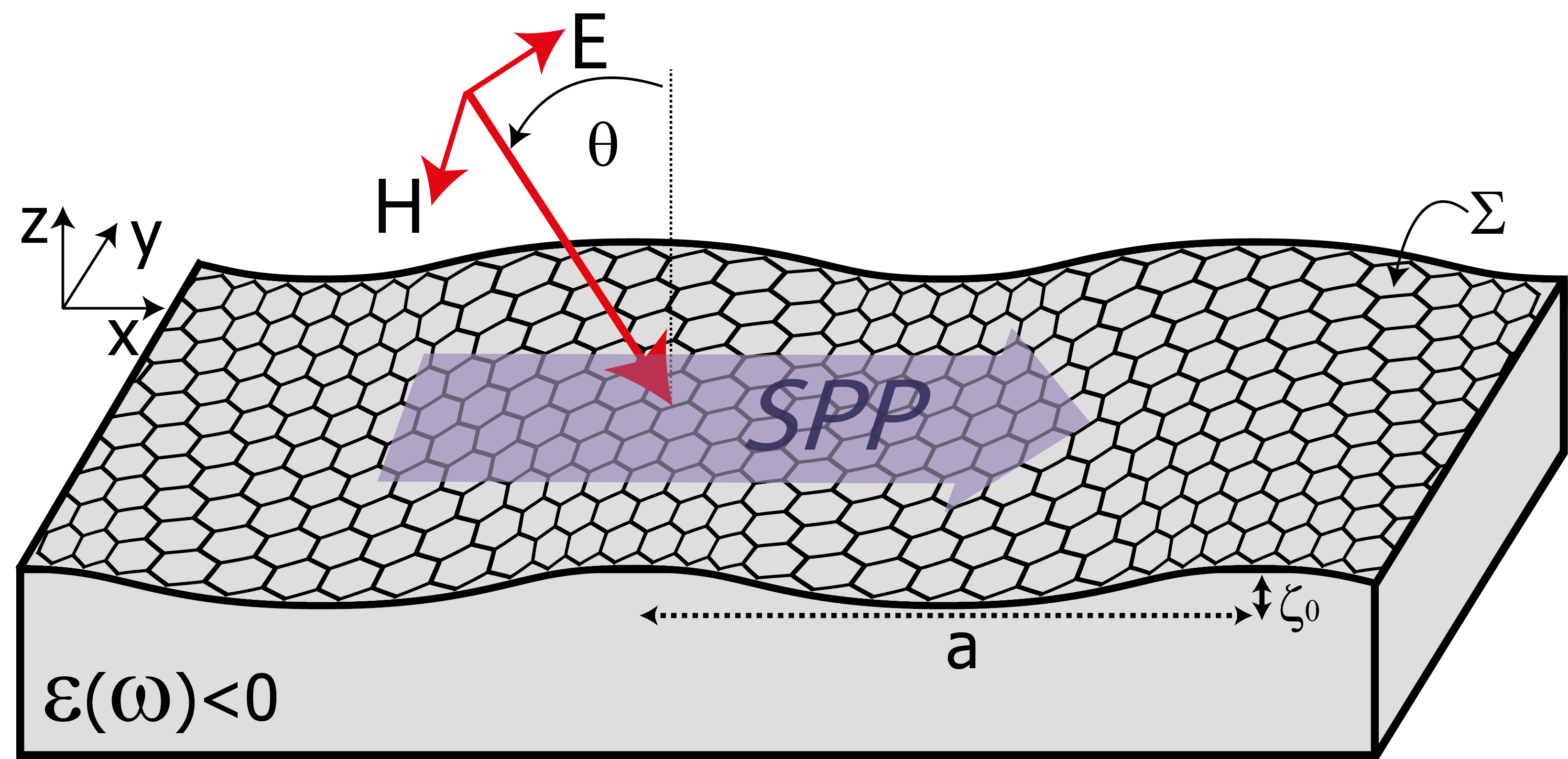
The system we have in mind is depicted in Fig. 1: incident light with angular frequency strikes the interface of a periodically structured conducting system coated with graphene. The light is transverse magnetic polarized, , where , and the parametrization of the boundary reads , with having the symmetry property, . In order to achieve electromagnetic energy confinement and SPP-related phenomena at the interface , the substrate is assumed to have in the frequency domain of interest.Zayatsa2005 In a practical implementation, the latter would be an engineered metamaterial,Pendry1996 in the relaxation regime (with being the effective plasma frequency and the relaxation rate).
The spatial periodicity of the present configuration is instrumental in order to excite SPPs via coupling to the radiation field: conservation of momentum requires that the projection of the wavevector of the incident photons onto the plane parallel to matches the wavevector of SPPs belonging to the hybrid structure. In flat surfaces the matching condition cannot be achieved since, in that case, the SPP dispersion relation lies to the right of the light line (i.e., ). The role of the periodic corrugated profile is thus to open Bragg scattering channels providing photons with the necessary wave vector (according to , for some integer ), thus allowing the excitation of SPPs to occur via direct illumination.
II Light Scattering: Exact Integral-Equation Formulation
The investigation of the optical properties of the hybrid graphene-metamaterial structure (Fig. 1) is carried out via exact numerical calculations of the reflected and transmitted fields. The total magnetic field is given by [here , and ], where the amplitudes are solutions of the wave equation,, with , and where (vacuum) and (substrate). The boundary conditions at the interface read ascomment_boundary_condition
| (1) | |||||
| (2) |
where the notation means that the fields (and derivatives) are to be evaluated taking values of approaching from above () or below () , denotes the derivative along the unit vector normal to the surface , directed from the vacuum into the substrate, and is the longitudinal current induced by graphene.
The surface current relates to the electromagnetic fields according to the constitutive relation (Ohm’s law), , where is the optical conductivity of the corrugated graphene sheet, which in general may depend on the coordinate, and is the tangential component of the electric field evaluated at . Here, denotes the unit vector tangent to and is the vacuum permittivity. In what follows, we approximate the optical conductivity by its bare value in the absence of corrugation. This is justified since the inclusion of a spatial modulation in does not significantly alter the optical properties to be discussed throughout (see Sec. V). We take as obtained by the random-phase approximation,colloquium with a relaxation rate meV, in consistency with typical values.pump_probe_epitaxial ; pump_probe_exfoliated ; Horgn2011
In order to solve for the full electromagnetic field we make use of an exact integral-equation method developed by Toigo et al.Toigo1977 This method exploits the integral form of Maxwell equations in order to express as an integral over the functions and . Making use of the Bloch property, , with , Toigo and co-workers reduce the well-known integral equationsBornAndWolf to a set of linear algebraic equations for the Fourier coefficients of . Here, we generalize their method as to include the effect of a metallic sheet with conductivity deposited on the corrugated surface . We just state the basic results: above (below) the selvedge region (), the reflected () [transmitted ()] wave is given by , where the term corresponds to the specular wave, and the remaining channels correspond to propagating modes (Bragg beams) or modes confined to the surface (evanescent waves), depending on whether
| (3) |
is pure imaginary or real, respectively. The amplitudes relate to the Fourier coefficients of the functions defined in Eqs. (1) and (2) according to
| (4) |
where () encodes the effect of the spatial profile of the interface, and
| (5) |
provides an infinite set of linear equations for the unknown coefficients .comment_approximation This system of equations is solved by retaining a finite number of coefficients, . The integer must be chosen sufficiently large so that convergence is obtained. The actual convergence properties of the present method depend crucially on the form of , and, in general, for corrugations with very large amplitudes and/or possessing discontinuities, convergence is not guaranteed.Garcia1978 ; Agassi1986 Here, we focus on periodic structures with a sinusoidal profile, , for which the functions have a well-known form and convergence is fast, i.e., only a few Fourier coefficients are required for good accuracy.comment_convergence
III Main results
We focus our discussion on normal incidence (), with the important remark that the reported features can be observed at . In that case, incident photons have , and hence the wavevectors of SPPs belonging to the hybrid structure coincide with the reciprocal lattice wavevectors, . In the relaxation regime and in the ideal scenario of no losses occurring inside the metamaterial (except when stated otherwise, we assume ), the fields cannot propagate into the substrate, and hence the incident light is totally reflected at the interface (in the absence of graphene). Yet, signatures of coupling of the incident light to SPPs are observed in the zeroth order (specular) reflectivity of metallic gratings.Sheng1982 ; Weber_Mills_1983 ; Zayatsa2005 The signatures arise because surface plasmonic waves excited at vacuum-metal structured interfaces via direct illumination are radiative: the excited SPPs reradiate into the vacuum via open Bragg channels (, with ). The resulting general decrease in the specular reflectivity is accompanied by pronounced features (e.g., dips and bumps) appearing at the SPPs resonances.
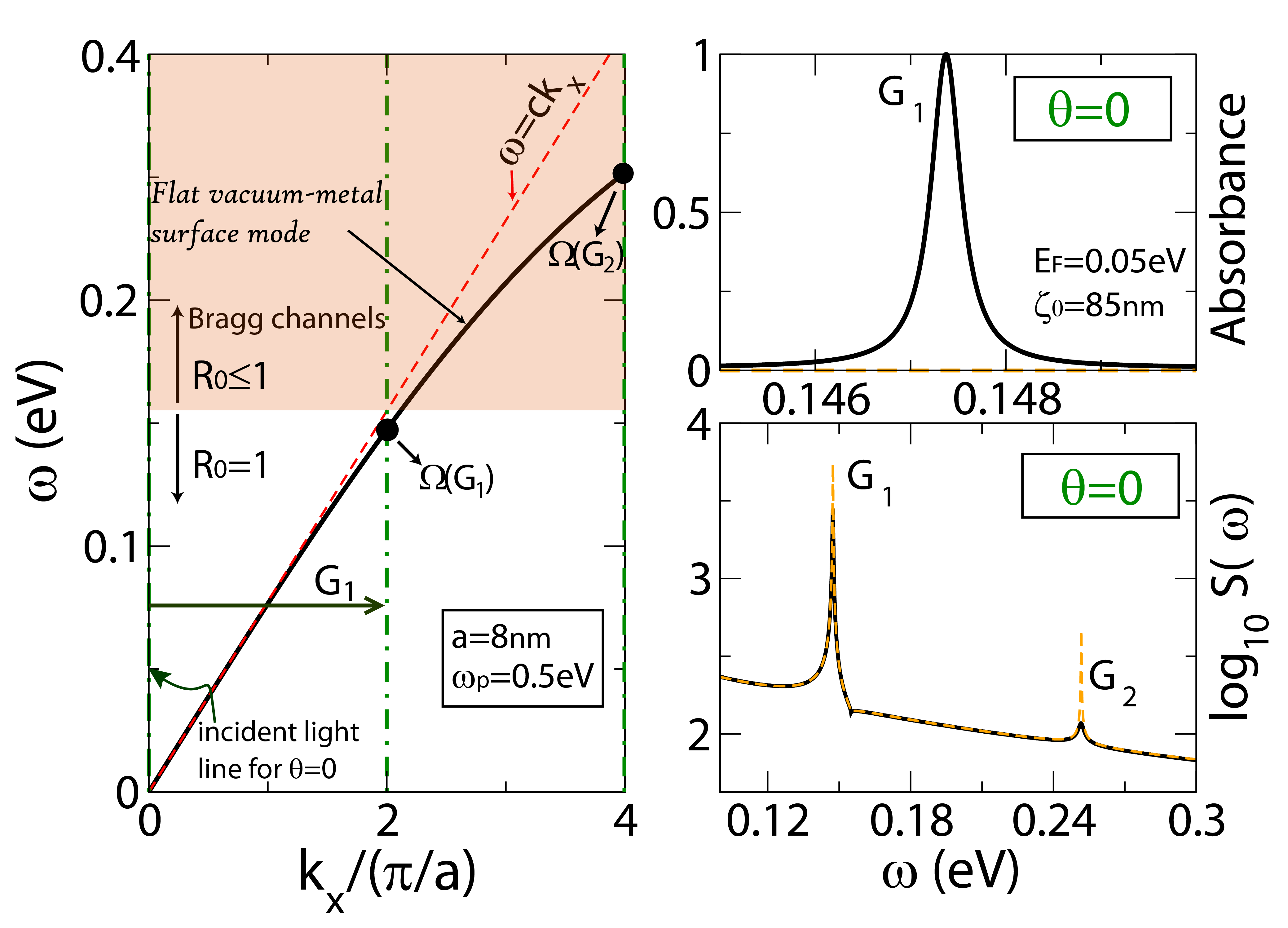
Coating the metamaterial interface with graphene introduces new channels for SPP dissipation, as encoded in the optical conductivity , due to Drude diffusive scattering and interband transitions.colloquium Based on general arguments,Herminghaus1994 we expect that if the SPP decay rate, , introduced by graphene, matches the broadening due to radiative decay, , the interference between the specular channel and the high-order Bragg beams suppresses the reflectivity, hence allowing the SPPs to be fully relaxed within the graphene sheet. The latter is borne out in Fig. 2 (right top panel), which shows the absorption near the lowest SPP resonance for a sinusoidal corrugation with nm and m, and at fixed Fermi energy, meV. We note that by varying the electronic density of the graphene sheet, it is possible to obtain complete absorption for as low as (see Fig. 3). We thus predict that small corrugation amplitudes are needed for obtaining complete light absorption.
IV Discussion
In order to understand the reported SPP-assisted enhanced absorption, we first characterize the spectrum of SPPs in the hybrid graphene-metamaterial system. The effect of a periodic spatial profile can be qualitatively appreciated by analogy with one-dimensional electrons subjected to a weak periodic potential: a length scale is introduced (, and the SPP spectrum acquires a multiband structure with period , with gaps opening at the Brillouin zone boundaries .Yuli2012 Indeed, SPP modes can be excited by photons via coupling through lattice reciprocal vectors, , with , whenever the frequency of the incident photon matches the frequency of a SPP in a given band, that is, . For shallow spatial profiles, the SPPs frequencies can be estimated by folding the flat-surface spectrum in the absence of graphene,comment_spectrum_withgraphene [with ], into the Brillouin zone and locating the intersection with the incident photon lineEconomou1969 ; Agranovich1982 ; Weber_Mills_1983 ; Zayatsa2005 (or equivalently, by the procedure illustrated in the left panel of Fig. 2). For a rigorous determination of the SPP spectrum for arbitrary corrugation profiles, we examine the poles of the scattering matrix , defined by , where and are 2-dimensional vectors containing the incoming (outgoing) modes in the vacuum (substrate), and the input field amplitudes, , respectively. The SPPs frequencies for a given wavevector can be obtained by localizing the peaks of the function .WCTan1999 The scattering function for normal incidence () is given in the right bottom panel of Fig. 2. Clearly, the SPPs frequencies are not significantly altered by the presence of graphene (as seen by the agreement of the peaks positions in both the solid and dashed linescomment_spectrum_withgraphene ). Moreover, these frequencies agree fairly well with the flat-spectrum estimate, shown in the left panel, based on perturbation theory arguments. The effect of graphene is therefore to change the spectral weight of scattering function around the vacuum-metal resonances, , without affecting too much their position (note that in Fig. 2 only the first two resonances, , are shown). The little sensitiveness of the resonant frequency of SPPs to the graphene sheet characteristics turns out to be of significance for experimental realizations. We can imagine that by changing , for example, by considering a metamaterial with an appropriate plasma frequency, the resonant frequencies can be controlled within a broad range of values, thus tailoring the hybrid structure for a desired spectral region. Another possibility is to probe the Fermi energy of graphene by optical measurements, either by monitoring changes in the reflectivity or by measuring small changes in the SPPs frequencies.
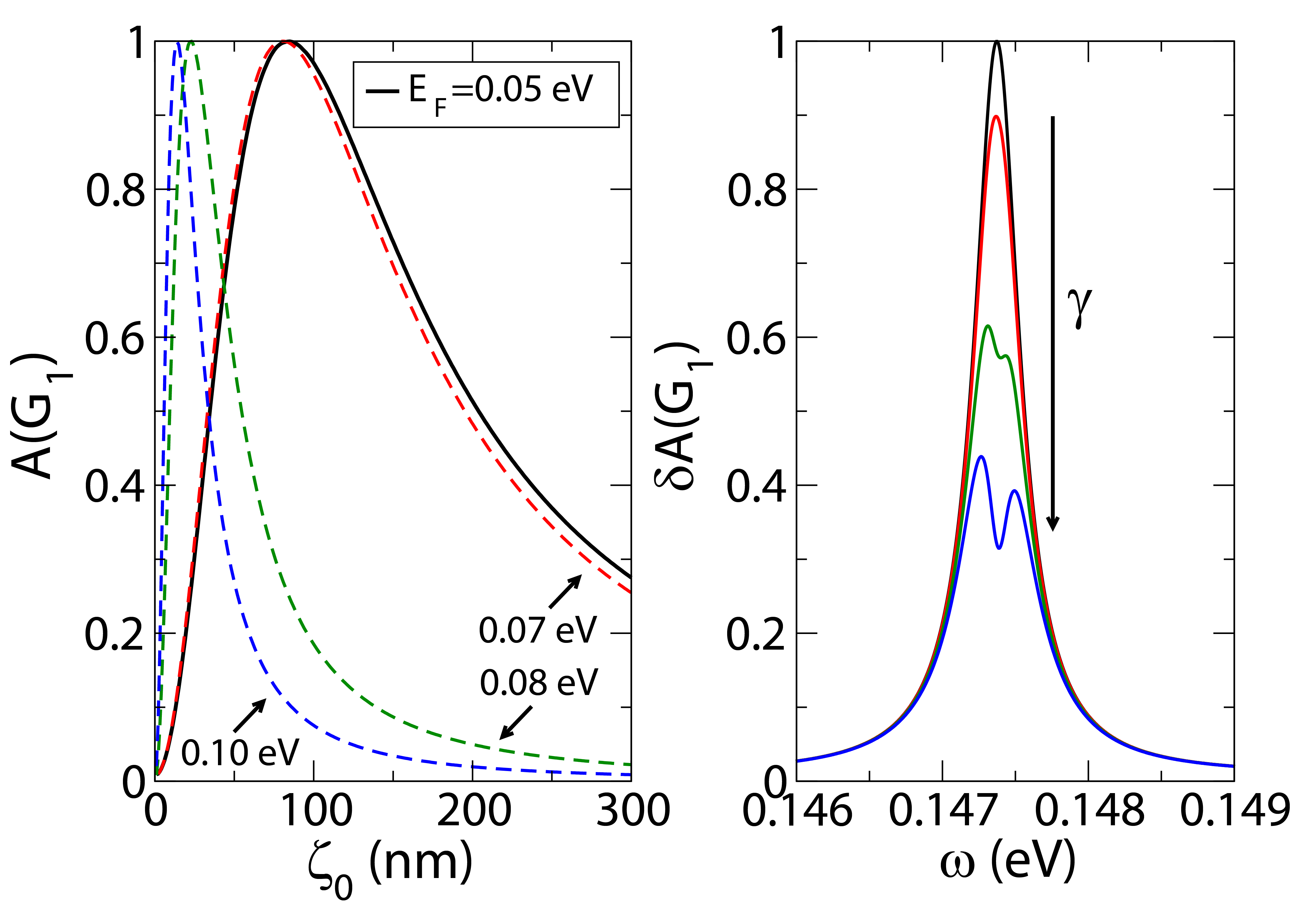
The dependence of the absorption line-shape on the corrugation amplitude shown in Fig. 3 (left panel) is similar to that found in metallic nanopatterned gratings with considerable ohmic losses.Weber_Mills_1983 ; WCTan1999 Initially, as increases, so does the coupling of SPPs to the radiation continuum, hence originating a monotonous increase in the absorption at resonance, . At some point, the radiative decay balances the SPP damping in the vicinity of graphene, , and the reflectivity is completely suppressed (absorption is maximum).WCTan1999 ; Herminghaus1994 Increasing beyond such value overcouples the SPP to the radiation field, and the specular wave is no longer canceled out by the reradiated field: decreases. Eventually, , and absorption becomes negligible, with all the energy being carried by the reflected wave. Evidently, the value of leading to complete light absorption depends on the Fermi energy of graphene, since the latter determines the effective value of . For instance, for eV, the maximum absorption occurs for very small (see Fig. 3), and given that, at lowest order, (see, e.g., Ref. Mills_Weber_1982, ), we can infer that the SPP damping in graphene is particularly small in such a case.
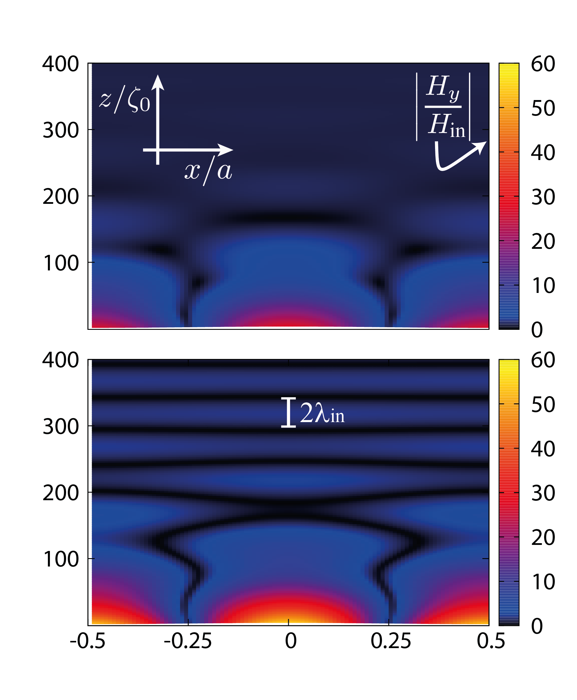
The calculation of the field intensity distribution in the vicinity of the surface further confirms the role played by the SPP decay channel introduced by graphene: In Fig. 4, we plot the magnetic field intensity in the vacuum for incident light in resonance with SPPs in the first band, . When graphene is absent (bottom panel), the large field enhancement effect typical of SPPs in corrugated interfaces is clearly observed,Mills_Weber_1982 ; Weber_Mills_1983 with in the near field. Here, the reflectivity is total as inferred by the sharp field interference pattern observed for . When graphene is introduced (top panel), the far-field interference pattern disappears, demonstrating the suppression of the reflected wave, while the near field displays more modest field enhancements, due to SPP damping in the graphene sheet, in consistency with arguments given previously.
V Final Remarks
We finish our discussion with a brief analysis of how losses in the metallic substrate and modulation of the graphene conductivity may affect the optical properties of the graphene-metamaterial hybrid system.
Losses in the metamaterial. When the dieletric function of the substrate is assumed to be a real function, absorption in the graphene sheet reaches 100% efficiency when adequate choices of the corrugation height are made (refer to the left panel in Fig. 3). On the other hand, in any realistic scenario, a trade-off between absorption in the graphene sheet and damping within the engineered substrate is expected to happen. In order to quantify the impact of a non-zero damping parameter (and hence a complex dieletric function) on the absorption efficiency of graphene paired up with the metallic substrate, we compute the change in the absorption, . Here, denotes the absorbance of the bare metamaterial interface (i.e., without graphene). (Note that subtracting to the absorbance of the hybrid system is necessary in order to correctly infer the amount of energy absorbed by the graphene sheet.) The right of Fig. 3 shows for a specific configuration ( eV and nm) and a few values of the damping rate . In these cases, and also more generally, we have found that damping frequencies as low as are required so that the graphene sheet is able to absorb considerable amounts of light (). With this respect, we recall that in the infrared range, ratios of the order of are achievable in metals as copper,Ordal1985 and hence the restriction on the substrate losses should not impose any fundamental limitation on the plasmonic performance of the hybrid system.
Modulation of the conductivity. When graphene adheres to a corrugated surface its local optical response becomes sensitive to local perturbations (e.g., via position-dependent strain). However, in the present case, the SPP dispersion relation of the hybrid system is practically unaffected by graphene’s intrinsic conductivity,comment_spectrum_withgraphene and thus the impact of modulations in in the optical properties of the hybrid system is expected to be weak. In order to assess this assumption, we have considered a conductivity profile , with the periodicity of the corrugated surface and magnitude variations of the order of 100%, namely, , and no qualitative changes relative to the unmodulated case have been found; for instance, the peak of the absorbance curve in Fig. 2 is seen to decrease by only about 0.1% and shifted by even a lesser amount.
VI Conclusion
We have shown that complete light absorption occurs in continuous sheets of graphene placed on top of simple plasmonic nano-structures. The physical mechanism on the basis of the two orders of magnitude boost in the graphene’s capability to absorb light demonstrated here lies in the efficient excitation of SPPs in the periodically corrugated interface of the hybrid graphene-metamaterial system. Absorbances far exceeding the graphene’s bare value (of about )Nair2008 are still achievable when intrinsic losses in the metamaterial are taken into account, provided that the damping rate is much smaller than relevant frequency scales, namely, the frequency of light and the plasma frequency of the metamaterial. In this so-called relaxation regime, , the plasmonic resonances of the hybrid system are determined by the plasma frequency of the metamaterial, allowing the frequency range for enhanced absorption to be set without the need of engineering graphene. Furthermore, the plasmonic-enhanced absorbance effect is shown to occur in a wide range of electronic densities of the graphene sheet (either low- or high- doped samples). The properties of the hybrid graphene-metamaterial system described in this work open interesting possibilities, such as the capture of light and further guidance and control of the excited plasmonic waves (e.g., by designing SPP propagation paths by inhomogeneous doping of the graphene sheetAshkan ), making this system a potential candidate for plasmonics applications, such as light-harvesting and photonic circuit implementation.
VII Acknowledgements
This work was supported by the National Research Foundation–Competitive Research Programme award “Novel 2D materials with tailored properties: beyond graphene (Grant No. R-144-000-295-281). A.F. acknowledges stimulating discussions with J. Viana-Gomes during his visit to the Graphene Research Centre (GRC) and technical assistance from M. D. Costa (GRC).
References
- (1) R. H. Ritchie, Phys. Rev. 106, 874 (1957).
- (2) V. M. Agranovich, and D. L. Mills, Surface Polaritons: Electromagnetic Waves at Surfaces and Interfaces, 1st Ed. (North-Holland, Amsterdam, 1982).
- (3) E. N. Economou, Phy. Rev. 182, 539 (1969).
- (4) J.J. Burke, G. I. Stegeman, and T. Tamir, Phys. Rev. B 33, 5186 (1986).
- (5) B. Hecht, H. Bielefeldt, L. Novotny, Y. Inouye, and D. W. Pohl, Phys. Rev. Lett. 77, 1889 (1996).
- (6) A. V. Zayatsa, I. I. Smolyaninovb, and A. A. Maradudin, Phys. Rep. 408, 131 (2005).
- (7) M. Moskovits, Rev. Mod. Phys. 57, 783 (1985).
- (8) K. Kneipp, Y. Wang, H. Kneipp, L. T. Perelman, I. Itzkan, R. R. Dasari, and M. S. Feld, Phys. Rev. Lett. 78, 1667 (1997).
- (9) J. Homola, S. S. Yee, and G. Gauglitz, Sensors and Actuators B: Chemical 54, 3 (1999).
- (10) D. K. Gramotnev, and S. I. Bozhevolnyi, Nature Photonics 4, 83 (2010).
- (11) W. L. Barnes, A. Dereux, and T. W. Ebbesen, Nature (London) 424, 824 (2003).
- (12) J. C. Weeber, A. Dereux, C. Girard, J. R. Krenn, and J. R. Goudonnet, Phys. Rev. B 60, 9061 (1999).
- (13) S. I. Bozhevolnyi, J. Erland, K. Leosson, P. M. Skovgaard, and J. M. Hvam, Phys. Rev. Lett. 86, 3008 (2001).
- (14) K. L. Kelly, E. Coronado, L. L. Zhao, and G. C. Schatz, J. Phys. Chem. B 107, 668 (2003).
- (15) A.V. Kabashin, E. Pevans, S. Pastkovsky, W. Hendren, G. A. Wurtz, R. Atkinson, R. Pollard, V. A. Podolskiy, and A. V. Zayats, Nat. Mater. 8, 867 (2009).
- (16) C. R. Williams, S. R. Andrews, S. A. Maier, A. I. Fernández-Domínguez, L. Martín-Moreno, and F. J. García-Vidal, Nature Photonics 2, 175 (2008).
- (17) J. Henzie, M. Hyung Lee, and T. W. Odom, Nature Nanotechnology 2, 549 (2007).
- (18) K. S. Novoselov, D. Jiang, F. Schedin, T. Booth, V. V. Khotkevich, S. V. Morozov, and A. K. Geim, Proc. Natl Acad. Sci. USA 102, 10451 (2005).
- (19) K. S. Novoselov, and A. H. Castro Neto, Phys. Scr. T146, 014006 (2012).
- (20) F. H. L. Koppens, D. E. Chang, and F. J. G. de Abajo, Nano Lett. 11, 3370 (2011).
- (21) A. H. Castro Neto, F. Guinea, N. M. R. Peres, K. S. Novoselov, and A. K. Geim, Rev. Mod. Phys 81, 109 (2009).
- (22) N. M. R. Peres, Rev. Mod. Phys 82, 2673 (2010).
- (23) M. Jablan, H. Buljan, and M. Soljačić, Phys. Rev. B 80, 245435 (2009).
- (24) S. A. Mikhailov, and K. Ziegler, Phys. Rev. Lett. 99, 016803 (2007).
- (25) A. Ferreira, N. M. R. Peres, and A. H. Castro Neto, Phys. Rev. B 85, 205426 (2012).
- (26) L. Ju, B. Geng, J. Horng, C. Girit, M. C. Martin, Z. Hao, H. A. Bechtel, X. Liang, A. Zettl, Y. R. Shen, and F. Wang, Nature Nanotechnology 6, 630 (2011).
- (27) A. Yu. Nikitin, F. Guinea, F. J. Garcia-Vidal, and L. Martin-Moreno, Phys. Rev. B 85, 081405 (2012).
- (28) S. Thongrattanasiri, F. H. L. Koppens, and F. J. G. de Abajo, Phys. Rev. Lett. 108, 047401 (2012).
- (29) R. R. Nair, P. Blake, A. N. Grigorenko, K. S. Novoselov, T. J. Booth, T. Stauber, N. M. R. Peres, A. K. Geim, Science 320, 1308 (2008).
- (30) H. Yan, X. Li, B. Chandra, G. Tulevski, Y. Wu, M. Freitag, W. Zhu, P.Avouris, and F. Xia, Nature Nanotechnology 7, 330 (2012).
- (31) J. B. Pendry, A. J. Holden, W. J. Stewart, and I. Youngs, Phys. Rev. Lett. 76, 4773 (1996).
- (32) In this work, we assume graphene to be in contact with the metamaterial substrate, in which case there is only one interface for the electromagnetic problem.
- (33) J. M. Dawlaty, S. Shivaraman, M. Chandrashekhar, F. Rana, and M. G. Spencer, Appl. Phys. Lett. 92, 042116 (2008).
- (34) M. Breusing, S. Kuehn, T. Winzer, E. Malić, F. Milde, N. Severin, J. P. Rabe, C. Ropers, A. Knorr, and T. Elsaesser, Phys. Rev. B 83, 153410 (2011).
- (35) J. Horng, C.-F. Chen, B. Geng, C. Girit, Y. Zhang, Z. Hao, H. A. Bechtel, M. Martin, A. Zettl, M. F. Crommie, Y. R. Shen, and F. Wang, Phys. Rev. B 83, 165113 (2011).
- (36) F. Toigo, A. Marvin, V. Celli, and N. R. Hill, Phys. Rev. B 15, 5618 (1977).
- (37) M. Born and E. Wolf, Principles of Optics, 5th Edition (Pergaxnon, Oxford, England, 1975).
- (38) In deriving Eqs. (4) and (5) we have multiplied the surface current term by the function . This approximation is extremely accurate for shallow corrugations (), and permits to obtain simpler expressions. For the parameters considered in this work, the maximum absolute error in the absorption line-shape by adopting this procedure is of the order of .
- (39) N. Garcia, V. Celli, and N. R. Hill, Phys. Rev. B 15, 5184 (1978).
- (40) D. Agassi, and T. F. George, Phys. Rev. B 33, 2393 (1986).
- (41) For the sinusoidal profile, the functions have the explicit solution: , where denotes the Bessel function of the second kind. Taking is sufficient to obtain accuracy up to 6 figures for large corrugation amplitudes, . The accuracy is even larger (up to 12 figures) for the amplitudes considered in this work.
- (42) P. Sheng, R. S. Stepleman, and P. N. Sanda, Phys. Rev. B 26, 2907 (1982).
- (43) M. Weber, and D. L. Mills, Phys. Rev. B 27, 2698 (1983).
- (44) S. Herminghaus, M. Klopfleisch, and H. J. Schmidt, J. Opt. Lett. 19, 293 (1994).
- (45) Y.V. Bludov, N. M. R. Peres, M. I. Vasilevskiy, Phys. Rev. B 85, 245409 (2012).
- (46) The explicit calculation shows that the SPP dispersion relation of a flat vacuum-metal interface is not altered significantly by the inclusion of a graphene sheet at the interface whenever the condition is met. Since the prefactor is of the order of the fine-structure constant, the latter condition is satisfied for (that is, ).
- (47) W.-C. Tan, T. W. Preist, J. R. Sambles, and N. P. Wanstall, Phys. Rev. B 59, 12661 (1999).
- (48) D. L. Mills and M. Weber, Phys. Rev. B 26, 1075 (1982).
- (49) M. A. Ordal, R. J. Bell, R. W. Alexander, L. L. Long, and M. R. Querry, Applied Optics 24, 4493 (1985).
- (50) A. Vakil, and N. Engheta, Science 332, 1291 (2011).