Fast quantum gate with superconducting flux qubits coupled to a cavity
Abstract
We present a way for fast implementation of a two-qubit controlled phase gate with superconducting flux qubits coupled to a cavity. A distinct feature of this proposal is that since only qubit-cavity resonant interaction and qubit-pulse resonant interaction are used, the gate can be performed much faster when compared with the previous proposals. This proposal does not require adjustment of the qubit level spacings during the gate operation. In addition, neither uniformity in the qubit parameters nor exact placement of qubits in the cavity is needed by this proposal.
pacs:
03.67.Lx, 42.50.Dv, 85.25.CpI. INTRODUCTION
The physical system composed of circuit cavities and superconducting qubits such as charge, phase and flux qubits has been considered as one of the most promising candidates for quantum information processing. This is because: (i) superconducting qubits and microwave cavities can be fabricated with modern integrated circuit technology, (ii) a superconducting qubit has relatively long decoherence time [1,2], and (iii) a superconducting microwave cavity or resonator acts as a “quantum bus” which can mediate long-range and fast interaction between distant superconducting qubits [3-5]. In addition, the strong coupling between the cavity field and superconducting qubits, which is difficult to achieve with atoms in a microwave cavity, was earlier predicted by theory [6,7] and has been experimentally demonstrated [8,9]. All of these features make superconducting qubit cavity QED very attractive for quantum information processing.
Over the past few years, there is much experimental progress in quantum information processing with superconducting qubits. Two-qubit controlled-phase, controlled-NOT, SWAP gates, or other two-qubit entangling gates have been experimentally demonstrated with supercoducting charge qubits coupled by a capacitor [10], phase qubits coupled via a capacitor [11], and flux qubits coupled through mutual inductance [12]. Also, three-qubit entangled states have been recently generated in experiments by using superconducting phase qubits coupled via a capacitor [13] or a superconducting phase qubit coupled to two microscopic two-level systems [14]. On the other hand, based on cavity QED technique, two-qubit quantum gates [4,15], two-qubit entanglement [5], two-qubit quantum algorithm [5], and quantum information transfer [4] have been experimentally demonstrated with superconducting charge qubits or transmon qubits coupled to a cavity or resonator. Moreover, based on cavity QED, experimental demonstration of three-qubit Toffoli gates [16-18], three-qubit entanglement [19] and three-qubit quantum error correction [17] with superconducting transmon qubits or phase qubits coupled to a resonator has been reported recently. However, to the best of our knowledge, no experimental demonstration of one of them with superconducting flux qubits in cavity QED has been reported.
It is known that two-qubit controlled-phase (CP) gates plus single-qubit gates form the building blocks of quantum information processors [20]. Theoretical methods for implementing a two-qubit CP gate [3,21-27] have been presented with flux qubits (e.g., SQUID qubits) or charge-flux qubits based on cavity QED technique. However, these methods have some disadvantages. For instances: (i) the methods presented in [3,21] require adjustment of the qubit level spacings during the operation; (ii) the methods proposed in [22,23] require slowly changing the Rabi frequencies to satisfy the adiabatic passage; and (iii) the approaches introduced in [24-27] require a second-order detuning to achieve an off-resonant Raman coupling between two relevant levels. Note that the adjustment of the qubit level spacings during the gate operation is undesirable and also may cause extra decoherence. In addition, when the adiabatic passage or a second-order detuning is applied, the gate becomes slow (the operation time required for the gate implementation is on the order of one microsecond to a few microseconds [23-25]).
In this paper, we propose an alternative method for realizing a two-qubit CP gate with four-level superconducting flux qubits coupled to a cavity or resonator. This proposal has the following advantages: (i) since only qubit-cavity resonant interaction and qubit-pulse resonant interaction are applied, the gate operation can be performed faster by two orders of magnitude, when compared with the previous proposals [22-27] requiring a second-order large detuning or adiabatic passage; (ii) the method does not require adjustment of the qubit level spacings (which however was needed by the previous proposals [3,21], thus decoherence caused by tuning the qubit level spacings is avoided; and (iii) the qubits are not required to have identical level spacings, therefore superconducting devices, which often have considerable parameter nonuniformity, can be used in this proposal. This work is interesting because it avoids most of the problems existing in the previous proposals [3,21-27] and the gate speed is significantly improved.
II. BASIC THEORY
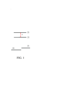
The flux qubits throughout this paper have four levels and as depicted in Fig. 1. In general, there exists the transition between the two lowest levels and [28], which however can be made to be weak via increasing the potential barrier between the two levels and [1,29,30]. The qubits with this four-level structure could be a radio-frequency superconducting quantum interference device (rf SQUID) consisting of one Josephson junction enclosed by a superconducting loop, or a superconducting device with three Josephson junctions enclosed by a superconducting loop. For flux qubits, the two logic states of a qubit are represented by the two lowest levels and
.1 Qubit-cavity resonant interaction
Consider a flux qubit with four levels as shown in Fig. 1. Suppose that the transition between the two levels and is resonant with the cavity mode. In the interaction picture and under the rotating-wave approximation, the interaction Hamiltonian of the qubit and the cavity mode is given by
| (1) |
where and are the photon creation and annihilation operators of the cavity mode, is the coupling constant between the cavity mode and the transition of the qubit, and .
Based on the Hamiltonian (1), it can be easily found that the initial states and of the qubit and the cavity mode evolve as follows
| (2) |
However, the state remains unchanged under the Hamiltonian (1).
The coupling strength may vary with different qubits due to non-uniform device parameters and/or non-exact placement of qubits in the cavity. Therefore, in the operation below, will be replaced by and for qubits and , respectively.
.2 Qubit-pulse resonant interaction
Consider a flux qubit with four levels as depicted in Fig. 1, driven by a classical microwave pulse. Suppose that the pulse is resonant with the transition between the two levels and of the qubit. Here, the level is the lower energy level. In the interaction picture and under the rotating-wave approximation, the interaction Hamiltonian is given by
| (3) |
where is the Rabi frequency of the pulse and are the initial phase of the pulse. Based on the Hamiltonian (3), it is straightforward to show that a pulse of duration results in the following state transformation
| (4) |
which can be completed within a very short time, by increasing the pulse Rabi frequency (i.e., by increasing the intensity of the pulse).
III. REALIZING A TWO-QUBIT CP GATE
Let us consider two flux qubits 1 and 2. Each qubit has a four-level configuration as depicted in Fig. 1. To begin with, it should be mentioned that during the gate implementation, the following conditions are required, which are: (i) the cavity mode is resonant with the transition of each qubit, (ii) the cavity mode is highly detuned (decoupled) from the transition between any other two levels, and (iii) the pulse is resonant with the transition between two relevant levels of each qubit but highly detuned (decoupled) from the transition between any two irrelevant levels of each qubit.
For superconducting qubits, it is experimentally challenging to design the qubits with identical level spacings, due to nonuniformity of the device parameters. However, once superconducting qubits are designed, their level spacings can be readily adjusted by changing the external parameters (e.g., changing the external magnetic flux for supercondcuting charge qubits, the flux bias or current bias in the case of superconducting phase qubits and flux qubits) [1,29-31]. Experimentally, it is difficult to adjust all level spacings for two superconducting qubits to be identical, but it is easy to adjust the level spacing between certain two levels to be the same for the two qubits [32]. For instance, for the two flux qubits 1 and 2 here, it is hard to make all of the , , …, and level spacings of qubit 1 to be, respectively, the same as the , , …, and level spacings of qubit 2, by adjusting the level spacings of the two qubits. But, the level spacing between certain two levels (e.g., the levels and ) for the two qubits 1 and 2 can be adjusted to be identical, which can be achieved by changing the external flux biases applied to the superconducting loops of qubits 1 and 2. Thus, the first condition described above can be achieved since one can set the level spacing between the two levels and to be the same for qubits 1 and 2, as discussed here. In addition, the second and third conditions above can be also achieved via prior adjustment of the qubit level spacings before the operation. Having these in mind, we now give a detailed discussion on implementing a two-qubit CP gate.
For two qubits, there are a total number of four computational basis states, denoted by and , respectively. A two-qubit CP gate is described by
| (5) |
where The transformation (5) implies that only when the control qubit (the first qubit) is in the state a phase flip, i.e, a change from the sign to the sign happens to the state of the target qubit (the second qubit).
The cavity mode is initially in the vacuum state The procedure for realizing a two-qubit CP gate is listed as follows:
Step (i): Apply a pulse (with a frequency a phase and a duration ) to qubit [Fig. 2(a)], to transform the state to as described by equation (4). Wait for a time to have the cavity mode resonantly interacting with the transition of qubit [Fig. 2(a′)], such that the state is transformed to as described by equation (2) while the state remains unchanged. Then, apply a pulse (with a frequency a phase and a duration ) to qubit [Fig. 2(a′′)], to transform the state to as described by equation (4).
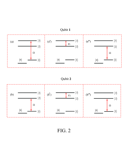
It can be checked that after the operation of this step, the following transformation is obtained:
| (6) |
The result (6) shows that after this step of operation, a photon is emitted into the cavity, in the case when qubit 1 is initially in the state before the operation.
Step (ii): Apply a pulse (with a frequency a phase and a duration ) to qubit [Fig. 2(b)], to transform the state to . Wait for a time to have the cavity mode resonantly interacting with the transition of qubit [Fig. 2(b′)], such that the state changes to while the states and remain unchanged. Then, apply a pulse (with a frequency a phase and a duration ) to qubit [Fig. 2(b′′)], to transform the state back to
One can verify that after the operation of this step, the following transformation is obtained:
| (7) |
Step (iii): Apply a pulse (with a frequency a phase and a duration ) to qubit [Fig. 2(a′′)], resulting in the transformation . Wait for a time to have the cavity mode resonantly interacting with the transition of qubit [Fig. 2(a′)], such that . Then, apply a pulse (with a frequency a phase and a duration ) to qubit [Fig. 2(a)], leading to
It can be checked that after the operation of this step, the following transformation is obtained:
| (8) |
The equations (6) and (8) show that during the operations of step (i) and step (iii) on qubit 1 and the cavity, the states and of qubit 2 do not change. In addition, Eq. (7) shows that during the operation of step (ii) on qubit 2 and the cavity, the states and of qubit 1 remain unchanged. This is because the cavity mode was initially assumed to be resonant with the transition but highly detuned (decoupled ) from the transition between any other two levels of each qubit.
Based on the equations (6-8), it can be found that the states of the whole system after each step of the above operations are summarized in the following equation:
| (9) |
This result (9) demonstrates that a phase flip happens to the state of the two qubits while the cavity mode returns to its original vacuum state after the operations above. Namely, a two-qubit CP gate described by equation (5) is realized after the above operations.
From the description above, it can be seen that the proposal presented here does not require adiabatic passage (slow variation of the pulse Rabi frequency), or a second-order large detuning during the entire operation. Here, is the first-order large detuning between the cavity frequency and the transition frequency of the qubits, while is the first-order large detuning between the pulse frequency and the transition frequency of the qubits. In addition, one can see that the present proposal does not require a first-order large detuning or either. Note that only resonant qubit-cavity interaction and resonant qubit-pulse interaction are used in this proposal. In contrast, a second-order large detuning or adiabatic passage was employed for the previous proposals [22-27]. Thus, when compared with the previous proposals [22-27], the gate operation in this proposal can be performed faster by two orders of magnitude.
In addition, it can be seen from the gate operation that this proposal does not require adjustment of the level spacings of the qubits during the entire operation, which however was needed by the previous proposals [3,21]. Furthermore, since the qubit-cavity coupling constants and are not required to be identical, either nonuniformity in the qubit device parameters (resulting in nonidentical qubit level spacings) or non-exact placement of qubits in the cavity is allowed by this proposal.
Several points need to be addressed as follows:
(i) We note that for the gate implementation, four levels of each qubit are necessary in order to have an irrelevant qubit (qubit 1 or qubit 2) to be decoupled from the cavity mode during the gate operation.
(ii) The decay of the level of each qubit can be suppressed by increasing the potential barrier between the two lowest levels and [29].
(iii) For simplicity, we considered the identical Rabi frequency for each pulse during the operations above. Note that this requirement is unnecessary. The Rabi frequency for each pulse can be different and thus the pulse durations for each step of operations above can be adjusted accordingly.
(iv) During the gate operation, to have the effect of the qubit-cavity resonant interaction during the pulse negligible, the pulse Rabi frequency needs to be set such that .
IV. POSSIBLE EXPERIMENTAL IMPLEMENTATION
As shown above, it can be found that the total operation time is given by
| (10) |
The should be much shorter than the energy relaxation time and dephasing time of the levels and (note that the level has a longer decoherence time than both levels and ), such that decoherence, caused due to spontaneous decay and dephasing process of the qubits, is negligible during the operation. And, the needs to be much shorter than the lifetime of the cavity photon, which is given by such that the decay of the cavity photon can be neglected during the operation. Here, is the (loaded) quality factor of the cavity and is the cavity field frequency. To obtain these requirements, one can design the qubits ( solid-state qubits) to have sufficiently long decoherence time, and choose a high- cavity such that
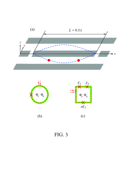
For the sake of definitiveness, let us consider the experimental possibility using two identical superconducting flux qubits coupled to a one-dimensional coplanar waveguide transmission line resonator [Fig. 3(a)]. For superconducting qubits, the typical qubit transition frequency (which is the transition frequency between the two lowest levels and in our present case) is between 5 and 10 GHz [4,5,11-19]. As an example, let us consider two identical flux qubits with the transition frequency GHz, the transition frequency GHz, and the transition frequency GHz. The qubits with these transition frequencies may be available by designing the qubits with device parameters chosen appropriately. Without loss of generality, assume MHz, which is available in experiments (see, e.g., Refs. [15,19,33]). By choosing MHz [33], we have ns. Note that the decoherence time of levels and have not been measured in experiments, to the best of our knowledge. However, we remark that a decoherence time of the levels and which is sufficiently longer than ns, may be available within the present technique or in the near future due to the rapid development of superconducting quantum circuits with long decoherence time [2]. In addition, for the qubits considered here, the resonator frequency is GHz [15,33]. For a resonator with this frequency and a quality factor , we have ns, which is much longer than the operation time here. Note that superconducting coplanar waveguide resonators with a (loaded) quality factor have been experimentally demonstrated [34,35].
Finally, for superconducting qubits located in a microwave resonator, the qubits can be well separated, because the dimension of a superconducting qubit is 10 to 100 micrometers while the wavelength of the cavity mode for a microwave superconducting resonator is 1 to a few centimeters [6,21]. As long as the two qubits are well separated in space [Fig. 3(a)], the loop current of one qubit affecting the other qubit and the direct coupling between the two qubits are negligible, which can be reached by designing the qubits and the resonator appropriately [6,21]. We should mention that further investigation is needed for each particular experimental setup. However, this requires a rather lengthy and complex analysis, which is beyond the scope of this theoretical work.
V. CONCLUSION
We have presented a way to fast realize a two-qubit controlled-phase gate with four-level superconducting flux qubits in cavity QED. As shown above, this proposal has the following advantages: (i) The coupling constants of each qubit with the cavity are not required to be identical, which makes neither identical qubits nor exact placement of qubits in the cavity to be required by this proposal; (iii) No adjustment of the level spacings of qubits during the entire operation is needed, thus decoherence caused due to the adjustment of the level spacings is avoided in this proposal; and (iv) Because only qubit-cavity resonant interaction and qubit-pulse resonant interaction are used by this proposal, the gate can be performed much faster when compared with the previous proposals.
ACKNOWLEDGMENTS
This work was supported in part by the National Natural Science Foundation of China under Grant No. 11074062, the Zhejiang Natural Science Foundation under Grant No. Y6100098, the Open Fund from the SKLPS of ECNU, and the funds from Hangzhou Normal University.
References
- (1) J. Clarke and F. K. Wilhelm, Nature (London) 453 (2008), 1031.
- (2) (energy relaxation time) and (dephasing time) can be made to be sufficiently long for the state of art superconducting qubits, e.g., s [see J. Bylander et al., Nature Phys. 7 (2011), 565] and s [see H. Paik et al., Phys. Rev. Lett. 107 (2011), 240501].
- (3) C.P. Yang, S.I. Chu and S. Han, Phys. Rev. A 67 (2003), 042311.
- (4) J. Majer et al., Nature (London) 449 (2007), 443.
- (5) L. DiCarlo et al., Nature (London) 460 (2009), 240.
- (6) C.P. Yang, S.I. Chu and S. Han, Phys. Rev. Lett. 92 (2004), 117902.
- (7) A. Blais, R.S. Huang, A. Wallraff, S.M. Girvin and R.J. Schoelkopf, Phys. Rev. A 69 (2004), 062320.
- (8) I. Chiorescu et al., Nature (London) 431 (2004), 159.
- (9) A. Wallraff et al., Nature (London) 431 (2004), 162.
- (10) T. Yamamoto, Y.A. Pashkin, O. Astafiev, Y. Nakamura and J. S. Tsai, Nature (London) 425 (2003), 941.
- (11) R.C. Bialczak et al., Nature Physics 6 (2010), 409; T. Yamamoto et al., arXiv:1006.5084.
- (12) J.H. Plantenberg, P.C. de Groot, C.J.P.M. Harmans and J. E. Mooij, Nature (London) 447 (2007), 836.
- (13) M. Neeley et al., Nature (London) 467 (2010), 570.
- (14) G. Sun, X. Wen, B. Mao, J. Chen, Y. Yu, P. Wu and S. Han, Nature Communications 1 (2010), 51.
- (15) P.J. Leek et al., Phys. Rev. B 79 (2009), 180511(R).
- (16) A. Fedorov, L. Steffen, M. Baur, M. P. da Silva and A. Wallraff, Nature (London) 481 (2012), 170.
- (17) M. D. Reed et al., arXiv:1109.4948.
- (18) M. Mariantoni et al., Science 334 (2011), 61.
- (19) L. DiCarlo et al., Nature (London) 467 (2010), 574.
- (20) T. Sleator and H. Weinfurter, Phys. Rev. Lett. 74 (1995), 4087.
- (21) C.P. Yang and S. Han, Phys. Rev. A 72 (2005), 032311.
- (22) K.H. Song, S.H. Xiang, Q. Liu and D.H. Lu, Phys. Rev. A 75 (2007), 032347.
- (23) P. Zhang, Z.D. Wang, J.D. Sun and C.P. Sun, Phys. Rev. A 71 (2005), 042301.
- (24) C.P. Yang, S.I. Chu and S. Han, Phys. Rev. A 70 (2004), 044303.
- (25) C.P. Yang, S.I. Chu and S. Han, J. Phys.: Condens. Matter 16 (2004), 1907.
- (26) K.H. Song, Z.W. Zhou and G.C. Guo, Phys. Rev. A 71 (2005), 052310.
- (27) K.H. Song, Chin. Phys. No.2 15 (2006), 286.
- (28) X.Y. Liu, J.Q. You, L.F. Wei, C.P. Sun and F. Nori, Phys. Rev. Lett. 95 (2005), 087001.
- (29) S. Han, J. Lapointe, J.E. Lukens, Single-Electron Tunneling and Mesoscopic Devices (Springer-Verlag, Berlin-Heidelberg, 1991), Vol. 31, pp. 219-222.
- (30) M. Neeley et al., Nature Phys. 4 (2008), 523.
- (31) C.P. Yang, S.B. Zheng and F. Nori, Phys. Rev. A 82 (2010), 062326.
- (32) Y. Yu and S. Han (private communication).
- (33) M. Baur et al., Phys. Rev. Lett. 102 (2009), 243602.
- (34) W. Chen, D.A. Bennett, V. Patel and J.E. Lukens, Supercond. Sci. Technol. 21 (2008), 075013.
- (35) P.J. Leek et al., Phys. Rev. Lett. 104 (2010), 100504.