Corresponding author: R. W. Ogburn, 382 Via Pueblo Mall, Stanford, CA 94305. E-mail: ogburn@stanford.edu
BICEP2 and Keck Array operational overview and status of observations
Abstract
The Bicep2 and Keck Array experiments are designed to measure the polarization of the cosmic microwave background (CMB) on angular scales of 2-4 degrees (–100). This is the region in which the -mode signal, a signature prediction of cosmic inflation, is expected to peak. Bicep2 was deployed to the South Pole at the end of 2009 and is in the middle of its third year of observing with 500 polarization-sensitive detectors at . The Keck Array was deployed to the South Pole at the end of 2010, initially with three receivers—each similar to Bicep2. An additional two receivers have been added during the 2011-12 summer. We give an overview of the two experiments, report on substantial gains in the sensitivity of the two experiments after post-deployment optimization, and show preliminary maps of CMB polarization from Bicep2.
keywords:
Cosmic microwave background, microwave, TES, polarization, inflation, gravitational waves, cosmology1 INTRODUCTION
Over the past 15 years, the CDM theory has emerged as the “standard model” of cosmology. It describes a universe in which cold dark matter drives the formation of structure, and dark energy (or a cosmological constant) causes accelerating expansion of space. This concordance model explains the observed universe well, but leaves several important questions unanswered, such as the nature of the dark energy and dark matter. It accommodates, but does not predict, the observed flatness, homogeneity, and isotropy of the universe. These three properties can be explained by the addition to the model of cosmic inflation. If the universe went through an inflationary phase in the first instant after the Big Bang, this rapid, exponential expansion from a single microscopic volume would have smoothed out spatial curvature. The observed homogeneity and isotropy arise from the fact that the entire observable universe would have been in causal contact before inflation. Quantum fluctuations in the inflaton field give rise to scale-invariant density fluctuations that would seed structure formation and the primary temperature anisotropy of the cosmic microwave background (CMB). Current CMB observations are in good agreement with inflationary predictions. [1, 2]
In addition to these scalar density perturbations, inflation also generates primordial gravitational waves, i.e. tensor metric perturbations. Both types of perturbation give rise to temperature variations at the time when CMB photons last scattered, but with different spatial structure; they accordingly lead to different signatures in the CMB. They can be distinguished by decomposing the patterns of CMB polarization into two classes: the -modes, which have even parity and arise from scalar and tensor perturbations; and the -modes, which have odd parity and arise from tensor perturbations only. The detection of -modes would confirm a key prediction of inflation, and a measurement of (or upper limit on) the amplitude of -modes would provide information about the energy scale of inflation, which determines the tensor-to-scalar ratio .[3]
 |
The DASI experiment measured degree-scale -modes in 2002, the first detection of CMB polarization.[4] The amplitude of -modes is expected to be lower, and their detection remains an open challenge. The Bicep2, and Keck Array experiments have been designed to meet this challenge. The two experiments adopt elements from the successful Bicep telescope, which observed from 2006–08. Bicep has set the most sensitive limits on -mode polarization of the CMB in the range , and constrained at 95% confidence level.[5, 6] Bicep2 and the Keck Array use a new detector technology, the Caltech-JPL antenna-coupled TES arrays.[7, 8] These detectors are read out using NIST SQUID amplifiers with the University of British Columbia MCE control and readout electronics.[9] The monolithic fabrication and multiplexed readout allow Bicep2 and the Keck Array to field larger numbers of detectors, for improved sensitivity over their predecessors. Bicep2 was deployed to the South Pole in late 2009[10, 11, 12] and has observed through 2010 and 2011, with a third year of observations now in progress.
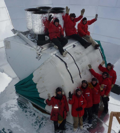
With its compact size and low cost, the Bicep-style refracting telescope can be scaled up by building an array of multiple receivers. This is the idea behind the Keck Array which uses the same detector technology as Bicep2 and a similar telescope design, with a few additional improvements.[13] Instead of consumable liquid helium, the Keck Array uses Cryomech pulse-tube coolers to provide cooling at and above. It uses the larger mount originally built for the DASI experiment and attached to the Martin A. Pomerantz Observatory (MAPO). This mount can accommodate up to five Bicep2-style receivers. The Keck Array was deployed and commissioned in December 2010–January 2011, with three cryostats housing three full focal planes of detectors. It observed with three receivers through 2011, and was upgraded to five receivers for the 2012 season (Fig. 1).
Both experiments observe the CMB in the same primary field as Bicep1, dubbed the ”Southern Hole,” with secondary observations of a bright region of the Galactic plane.
In this paper we present an overview of the Bicep2 and Keck Array experimental design; a number of improvements to the sensitivity of each experiment that have been made since deployment; and a look at - and -mode maps from two seasons of Bicep2 observation. Several companion papers in this volume present the sensitivity of the Keck Array (Kernasovskiy et al.[14]), studies of beam shape and differential pointing (Vieregg et al.[15]), and further developments in the detector fabrication for the Keck Array and other experiments (O’Brient et al.[16]).
2 EXPERIMENTAL OVERVIEW
 |
Bicep2 is a small-aperture refracting telescope that observes the CMB at from the South Pole. In many respects it follows the pattern of Bicep, which was designed to achieve high sensitivity with very low systematics on degree angular scales. The telescope contains relatively simple optics: two, on-axis lenses made from high-density polyethylene, with an aperture of and beams of 0.5∘ FHWM. This arrangement allows cooling of the optical components to 4 K for stability and low loading; efficient transportation and loading; and far-field () beam characterization using microwave sources raised on masts. The Keck Array expands this design in a modular way, by placing several Bicep2-style telescopes in a single mount. Each telescope observes in a single frequency band, with optics optimized for this frequency. Bicep2 and the current Keck Array receivers all observe at , but future Keck Array receivers may observe at and .
Bicep2 and the Keck Array observe the same primary CMB field as Bicep, an 800 deg2 patch of sky in the so-called Southern Hole. This area has unusually low dust and synchrotron emission, and is expected to have Galactic foreground confusion equivalent to .
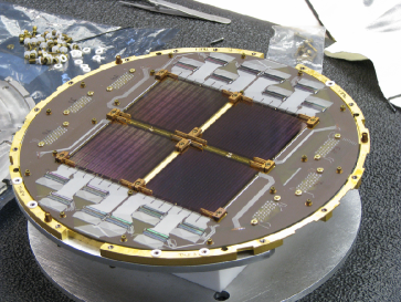
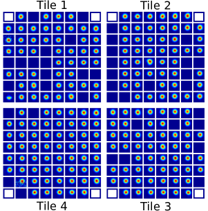
Bicep2 has pioneered a new detector technology in order to increase detector count and instrument sensitivity. The Caltech/JPL focal planes in Bicep2 and the Keck Array combine the beam-defining slot-antenna networks, band-defining filters, absorber, and transition-edge sensor (TES) detectors on the same silicon detector tiles. The actual Bicep2 focal plane and the far-field beam pattern of a single Keck Array receiver are shown in Fig. 2. This detector technology allows scaling to higher detector count by replacing hand-assembly of components in preceding experiments with monolithic fabrication. The Ti and Al TES elements are suspended on a SiN membrane along with a gold resistive absorber. The Ti transition temperature is in the range 470-530 mK. In order to facilitate beam characterization under higher loading, the Ti sensors are in series with an Al TES with of 1.2 K. Each telescope contains four detector tiles, each with 64 dual-polarization elements in an array. Two of the detector pairs on each tile are dark sensors with no coupling to antennas, for a total of 496 optically coupled, detectors and 16 dark TES detectors per receiver.111The detector counts for future and receivers will be different. Bicep2 has two fewer dark pairs, for a total of 12 dark and 500 optically coupled TESs. The detectors are designed to be read out with NIST three-stage SQUID hardware and the University of British Columbia Multi-Channel Electronics (MCE) system, with time-domain multiplexing. The technology of antenna-coupled TES detectors with multiplexed readout has allowed Bicep2 to increase the detector count of Bicep by a factor of five. The Keck Array, with five telescopes, increases this detector count by a further factor of five.
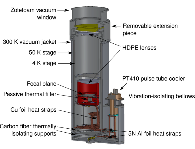
Each telescope is housed within a cryostat that provides cooling to 4 K. The Bicep2 and Keck Array designs have progressively eliminated consumable cryogens, for which the Amundsen-Scott South Pole Station has limited storage and transportation capacity. Bicep2 sits inside a liquid helium cryostat from Redstone Aerospace222http://www.redstoneaerospace.com/, which is similar to the Bicep dewar but replaces a liquid nitrogen jacket with a vapor-cooled shield. The helium reservoir has a capacity of 100 L, and consumes about 22 L/day during routine observing. The Keck Array cryostats (Fig. 3), manufactured by Atlas UHV333http://www.atlasuhv.com/, have several major changes relative to Bicep2. They add a removable extension piece for a half-wave plate, eliminate the liquid helium reservoirs, and add a housing for a Cryomech PT410 two-stage pulse tube cooler mounted on vibration-isolating bellows. The pulse tube coolers are rated to maintain on the first stage, with loading up to 45 W, and on the second stage, with loading of . The thermal linkage from the pulse tube cold head to the 4 K plate of the telescope is made from a stack of high-purity Al foil, which provides excellent thermal conduction while isolating the telescope from vibration of the pulse tube. The Keck Array cryocoolers and thermal linkage have demonstrated excellent performance after deployment. During standard observing, the cooler achieves temperatures at the pulse tube second stage and on the telescope side of the Al strap. The first stage of the cryocooler maintains .
Cooling below is provided by a Duband three-stage 4He/3He/3He sorption refrigerator operating in a closed cycle. Bicep2 has made several improvements in the thermal architecture in order to improve stability and reduce microphonic pickup. These have also been adopted by the Keck Array. The focal plane is cooled to base temperature through copper-foil heat straps and a passive thermal filter and copper heat straps that link it to the lowest-temperature stage of the fridge. The passive thermal filter is a stainless steel block, . The focal plane is supported by a truss structure of carbon-fiber rods, providing good thermal isolation from the stage.[17] Temperature control is achieved using resistive heaters and thermometers on the focal plane and at the fridge side of the passive thermal filter, servoed to suppress thermal fluctuations and to keep the focal plane at a temperature near 280 mK. The thermal architecture of Bicep2 has performed well. Estimates of the level at which thermal fluctuations on the focal plane enter CMB maps are lower than the corresponding estimates for Bicep, and the overall thermal stability while scanning has met our design goals.
The Bicep2 refrigerator can be recycled in slightly under 4 hours, after which it remains at a stable base temperature for at least 80 hours. The recycling operation and liquid helium fill are performed every three sidereal days, during a cryogenic service block of six hours. Several times per month, during clear weather, the cryogenic service block is also used for star observations, which are analyzed to characterize the telescope pointing and particularly to detect any shifts in the pointing. Star observations are performed several times per month, during In the Keck Array performance varies by receiver, and the observing schedule must accommodate the receiver with the longest service time and shortest hold time. The fridge recycling requires up to six hours, generally completing by the end of the six-hour service block. For the Keck Array this cryogenic service block occurs every two sidereal days.
3 SENSITIVITY IMPROVEMENTS
Several upgrades since the initial deployment of Bicep2 and the Keck Array have substantially increased their sensitivities. Although some details differ between the two experiments, these improvements have proceeded along parallel paths. We have reduced aliased noise by increasing the multiplexing rate, and optimized the detector biases for sensitivity and to minimize the number of unresponsive detectors.
Bicep2 has continued to run since deployment in a single cooldown without warming up or breaking vacuum. The Keck Array underwent major upgrades during the 2011-12 austral summer. This included the addition of two new receivers, the replacement of the focal plane and detectors in one receiver, and the removal of cold half-wave plates from two of the receivers.
3.1 Detector bias improvements
In both experiments, the TES detector bias voltages were chosen conservatively at initial deployment. These were revisited after several months of observation, with the goals of improving overall sensitivity and eliminating instabilities in some detectors. The new, optimized biases were chosen after study of the detector responsivity and stability in situ under good, winter observing conditions.
The detector bias is provided by the Multi-Channel Electronics (MCE) system. The TESs are biased with a common current bias for the 32 detectors444Each column also contains one open-input SQUID, for 33 total channels. in each multiplexing column. This current bias is converted into a voltage bias by a shunt resistor in parallel with the TES. This scheme allows some optimization of the biases for variation between detectors, since each multiplexing column can have a different bias voltage. The bias settings for each column must be chosen to give good responsivity and stability for all the detectors sharing that bias current. The responsivity is highest when the detector is within the middle portion of the superconducting-normal transition, i.e. the fractional resistance is not too close to zero or one. When the resistance is too low, the detector may also enter a state of unstable electrothermal feedback, which renders it unusable and can cause crosstalk signals on nearby channels. The optimal bias value depends on detector parameters such as thermal conductance and superconducting transition temperature. These are relatively consistent among the detectors in a single multiplexing column, which are always located on the same physical detector tile. The optimal bias values also depend on atmospheric loading. Under low-loading (winter) conditions, the highest responsivity is attained at relatively high bias voltage. Under high-loading (summer) conditions, on the other hand, lower bias voltages are required to keep well below one.
At deployment of Bicep2, the TES biases were chosen conservatively, during the austral summer. They were deliberately somewhat lower than the optimal per-column values, in order to avoid regions of decreasing responsivity. [12] During mid-2010, additional test data were taken at a variety of biases under winter conditions of low atmospheric loading. These studies led to improved bias selections, with an expected improvement of 10-20% in mapping speed. The new biases are the result of a careful balance between achieving the best sensitivity for as many detectors as possible, while minimizing the number of detectors that are either unresponsive or unstable. This optimization is done in the total NET of each column, rather than in a per-detector mean. Therefore, it has sometimes been acceptable to allow detectors with unusual bias requirements to fall off the transition entirely, in exchange for achieving better sensitivity in the others. The SQUID feedback is switched off for some unstable detectors, so that their noisy feedback signal does not affect neighboring channels through the known crosstalk mechanisms of the readout system.[18]
The new detector biases were adopted on September 14, 2010, and have been used through the remainder of the 2010 season, continuing through the full 2011 season and the 2012 season now in progress. The Keck Array has followed a similar procedure, with conservative bias settings at deployment replaced by more nearly optimal values after study under winter loading.[14]
3.2 Faster multiplexing
The multiplexing configuration used by Bicep2 in 2010 has been described in detail in a previous SPIE conference.[10] The row visit rate was 15 kHz, so any noise above 7.5 kHz that was not adequately suppressed before digitization could be aliased and impact the low-frequency region containing the CMB signal. Accordingly, the readout includes bandwidth-limiting inductors on the Nyquist chips. The resulting LR circuit is a single-pole filter with cutoff at –.555The of the LR circuit is the resistance of the TES itself, so the exact Nyquist frequency depends on the detector bias. Because the pole of this slow-rolloff filter is not far below the Nyquist filter of the multiplexing system in 15-kHz configuration, some amount of noise aliasing will occur.
| 15 kHz | 25 kHz | |
| Raw ADC sample rate | 50 MHz | 50 MHz |
| Row dwell | 98 samples | 60 samples |
| Row switching rate | 510 kHz | 833 kHz |
| Number of rows | 33 | 33 |
| Row revisit rate | 15.46 kHz | 25.25 kHz |
| Internal downsample | 150 | 140 |
| Output data rate per channel | 103 Hz | 180 Hz |
| Software downsample | 5 | 9 |
| Archived data rate | 20.6 Hz | 20.0 Hz |
A detailed noise model and comparison with observed noise levels were presented in an earlier SPIE conference.[12] It was found that, under 4–6 pW loading, the total noise-equivalent power (NEP) at low frequency was –. Photon noise was the largest contribution, with phonon noise (thermal fluctuation noise) at a comparable but lower level. Excess noise was also seen, and became dominant above 100 Hz. When multiplexing at 15 kHz, this excess noise was partly aliased into the low-frequency () science band, raising the total NEP to –.
Although this noise aliasing was understood at the time of deployment, it was not possible to shift the Nyquist filter because higher-inductance Nyquist chips were not available. Instead, it was anticipated that the noise aliasing could be ameliorated by shifting to a faster multiplexing rate. This requires a shorter dwell time on each row. The dwell time must be long enough that all transients associated with row switching have fully settled before moving on to the next row. These transients are a form of crosstalk between detectors in neighboring multiplexing rows.[18] Bicep2 continued to operate at 15-kHz readout until it could be demonstrated that a faster multiplexing rate would not increase row-switching crosstalk to unacceptable levels.
These studies of crosstalk and multiplexing rate were performed in late 2010, and it was found that (after making other adjustments to the SQUID bias settings) the readout rate could be increased without significant increase in crosstalk. As part of the 2010–11 summer upgrades, Bicep2 began to run with 25 kHz row switching. The new multiplexing parameters are shown in Table 1. We expected the reduction in aliased noise to yield a sensitivity gain of about 20% in the Bicep2 2011 and 2012 data.[12] The actual gains in sensitivity are discussed in Sec. 4.2.
The Keck Array was able to obtain Nyquist chips with inductors for four of its five receivers (all except rx0). This reduced the noise aliasing, but there remains a further benefit from faster readout. The initial deployment continued to use the well-tested 15-kHz multiplexing configuration, pending successful outcome of the 25-kHz change in Bicep2 and study of crosstalk in the slightly different Keck Array readout hardware. Since the faster readout was found also to work well in Keck Array with acceptable levels of crosstalk, the Keck Array row-switching rate was increased to 25 kHz during the 2011-12 summer. Although the Keck Array uses newer versions of the MCE hardware and firmware, allowing greater freedom in the choice of multiplexing parameters, we have adopted the same values used in Bicep2 for consistency and because they have already been demonstrated to work well. As a result, the Bicep2 2010 and Keck Array 2011 data sets use the same 15-kHz readout settings, and the Bicep2 2011-12 and Keck Array 2012 data sets use the same 25-kHz readout settings.
3.3 Temperature control
The Bicep2 and Keck Array focal planes are cooled to by Duband three-stage 4He/3He/3He sorption refrigerators operating in a closed cycle. The thermal path between the refrigerator and the focal plane has been designed to isolate the focal plane assembly from microphonic noise and from short-period thermal fluctuations. The -K, -mK, and base temperature stages of the refrigerator are connected to the truss assembly behind the focal plane by flexible, straps of layered copper foil. The -mK strap is attached to a stainless steel passive thermal filter that effectively isolates the focal plane from thermal fluctuations faster than about .[10]
The temperatures of the thermal straps, focal plane, and detector tile are monitored with neutron-transmutation doped (NTD) germanium thermistors. These are paired with heaters that provide for active thermal control in several possible configurations. In standard observing, the primary thermal control is on the fridge side (“dirty” side) of the passive thermal filter. This control loop is tuned to have -Hz bandwidth in order to remove temperature variations produced in the refrigerator as the telescope scans. The remaining small fluctuations are strongly attenuated by the stainless steel filter. The heater on the focal plane copper plate is also servoed. This “slow” control loop has a time constant of and is intended to keep the detector tiles at the designated operating temperature, rather than to suppress thermal fluctuations.
The effectiveness of this thermal architecture is assessed using NTD germanium thermometers mounted on the detector tiles themselves. In the first year of Bicep2 observing, the thermometry suffered from elevated noise due to microphonic pickup in the high-impedance wiring and excess noise in the room-temperature readout electronics. This additional noise had minimal effect on the thermal stability of the detector tiles, as it was well above the bandwidth of the thermal control loop on the focal plane. However, it did impede efforts to characterize the thermal performance of the system.
For the second and third seasons of Bicep2, the alternating current thermistor bias signals have been increased in frequency from to in order to better avoid microphonic noise. An upgrade to the readout firmware allowed the use of nulling resistors and increased bias amplitudes (typical values in 2010 to in 2011–12) for higher signal-to-noise. The Keck Array uses a later hardware version of the digital electronics, which eliminates much of the excess noise seen by Bicep2.
3.4 Additional Keck Array receivers
The Keck Array initially deployed three receivers for the 2011 season, known as rx0, rx1, and rx2. Two new receivers were added during the 2011–12 summer, rx3 and rx4. In addition, the detectors in one receiver (rx1) were found to have degraded performance relative to the other recievers. Its focal plane unit was replaced as part of the year-two upgrades. Although the 2011 and 2012 receivers have all contained detectors at , the modular Keck Array design also allows the possibility of swapping in receivers at and in the future.
3.5 Half-wave plates
The Keck Array cryostat design included a removable extension to allow for additional thermal filters or for a stepped half-wave plate. During the 2011 season, two of the receivers, (rx1 and rx2) were actually equipped with sapphire half-wave plates cooled to , and wave-plate rotations were incorporated into an observing strategy based on the Bicep2 pattern.[10] Before each sidereal day’s observations, the telescope was rotated about the boresight axis, so that each day covered one of the four boresight orientations 68∘, 113∘, 248∘, 293∘. (These are identical to the boresight angles used by Bicep2, and allow separation of the Q and U Stokes parameters as well as providing a 180∘ jackknife for characterization and control of systematics). After four days of data-taking, covering all four boresight angles, the half-wave plates were stepped by 45∘. This procedure is repeated to cover the four half-wave-plate orientations 0, 45∘, 90∘, 135∘.
This observing pattern was intended to address the known differential pointing common to the antenna-coupled detectors ( in Bicep2[11], typically or smaller in the Keck Array[15]). The wave-plate rotation periodically exchanges the roles of the two detectors in each pair, while the boresight orientation and all other aspects of the observation remain fixed. Jackknife combinations of maps made at different half-wave plate orientations could be used to better characterize the differential pointing, and coadding maps over half-wave plate orientations would suppress the temperature-to-polarization leakage caused by differential pointing.
In the 2011 data set, the two receivers with half-wave plates were found to suffer from degraded optical responsivity and additional beam systematics that were difficult to understand. These issues disappeared when the half-wave plates were removed for 2012 observing.
4 PERFORMANCE AND RESULTS
Bicep2 has now completed two years of observing and is at the midpoint of its third year. We present measures of the observing efficiency and sensitivity, particularly showing the significant gain in sensitivity resulting from the upgrades described above. We also present preliminary maps from Bicep2, including maps of the Stokes Q and U parameters and and polarization.
The Keck Array has completed one year of observing and is now in the middle of its second year, with greatly improved sensitivity thanks to the additional receivers and other upgrades. A detailed discussion of the Keck Array 2012 sensitivity, along with preliminary maps, may be found in a companion paper (Kernasovskiy et al., this volume[14]).
 |
4.1 Observing efficiency
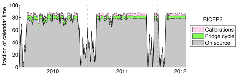
Bicep2 has a three-day cryogenic hold time and an ideal on-source fraction of 79.2%. This is the fraction of the time that the telescope would spend on the field if it continuously executed the standard three-day observing schedule, without interruption. (Because the Keck Array has a two-day observing cycle, its maximum observing efficiency is slightly lower, 70.0%.) Observing during the austral winter has generally been very close to this ideal value, as shown in Fig. 4. In particular, the on-source fraction since mid-2011 has never fallen far below the ideal value except during summer beam-mapping and other calibrations. The on-source fraction includes observations of a galactic field, which is allotted seven hours out of each three-day Bicep2 observing schedule. In all, Bicep2 has integrated on the primary CMB field for 4395 hours in 2010666from February 1, 4891 hours in 2011777from January 1, and 2034 hours so far in 2012888January 1-May 31. These on-source figures are before the application of weather and data-quality cuts, and include the scan turn-arounds, which are not used for mapmaking and account for 22.3% of on-source time.
4.2 Sensitivity
The sensitivity of Bicep2 has been calculated for three time periods: early 2010, late 2010, and 2011-12. The early 2010 period is as deployed, with -kHz multiplexing and conservative TES biases. The late 2010 period still has -kHz readout, but uses the improved TES biases for higher signal-to-noise ratio. The 2011-12 period uses the faster -kHz readout with lower noise, and the improved detector biases.
Sensitivity has been expressed as a noise-equivalent temperature (NET) as determined in two ways: from time-stream noise in the 0.1–1 Hz signal band; and from the variance of pixel values in maps differenced between left-going and right-going scans (a scan-direction jackknife map). The methodology for calculating the NETs is as in Kernasovskiy et al.[14] in these proceedings. The results are broadly consistent. The per-detector NETs are given in Table 2, and the overall instrument NETs in Table 3, after Brevik et al.[19, 20]. Note that the NET in the late-2010 period has been calculated only from timestream noise spectra, and not from maps.
| Period | Time stream NET, | Map NET, |
|---|---|---|
| Early 2010 | 433 | 422 |
| Late 2010 | 379 | - |
| 2011-12 | 316 | 313 |
| Period | Time stream NET, | Map NET, |
|---|---|---|
| Early 2010 | 22.1 | 21.5 |
| Late 2010 | 19.1 | - |
| 2011-12 | 15.9 | 15.8 |
4.3 Polarization maps
In Fig. 5 and 5 we show Bicep2 polarization maps made with the full-season 2010 and 2011 data sets. The data analysis is similar to that used in Bicep[5]. These maps do not include analysis techniques being developed[21] to remove the leaked polarization signal caused by differential pointing of the two detectors in a polarization-pair. The -mode signal around is readily apparent as a set of horizontal and vertical structures in the Stokes-Q map and diagonal structures in the Stokes-U map. The prevalence of -mode power at this angular scale results from the intrinsic shape of the -mode CMB spectrum (which increases with below ) and the Bicep2 beams, which are not sensitive to power at higher . We have estimated the map noise level by making separate maps from the left-going and right-going scans, differencing them, and dividing by two. This scan-direction jackknife map should contain noise at the same level as the fully coadded map, but no signal. From the pixel variance in the well-covered central region, we calculate noise levels in the Stokes Q and U maps of 0.139 and 0.138 K in square-degree pixels (8.3 K arcmin).
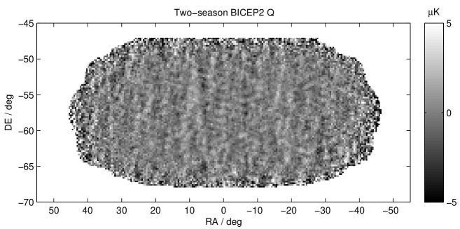
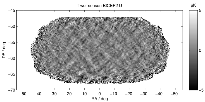
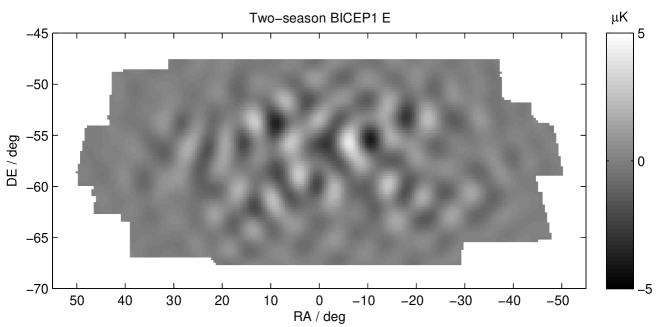
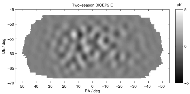
Fig. 6 and 7 shows the -mode and -mode patterns respectively reconstructed from two seasons of Bicep data[5] and from the two-season Stokes Q and U maps shown in Fig. 5 and 5. These have been apodized using the variance per map pixel, and filtered to the angular scale . The -mode maps are similar, and the lower level of power in the -mode map shows the improved sensitivity of Bicep2 relative to Bicep.


5 CONCLUSION
Bicep2 has completed two years of observation at the South Pole, and is currently in the middle of its third season. The Keck Array has completed its first season, with three receivers, and is now in the middle of its second season, with five receivers. Both have made substantial improvements to their sensitivity, through optimization of the detector biases and readout rate, and through the addition of new Keck Array receivers and replacement of detectors. Bicep2 has accumulated a total of 11320 hours on the primary CMB field. We have presented for the first time preliminary Bicep2 maps of the primary CMB field in polarization, showing the improvement in sensitivity over the original Bicep experiment.
Acknowledgements.
The Bicep2 and Keck Array projects have been made possible through support from the National Science Foundation (grant Nos. ANT-1044978 / ANT-1110087), the Keck Foundation, the Canada Foundation for Innovation, and the British Columbia Development Fund. Detector development has been made possible by the generous support of the Gordon and Betty Moore Foundation. RWO gratefully acknowledges support from the Kavli Institute for Particle Astrophysics and Cosmology. We are grateful to Steffen Richter as our 2010-12 Bicep2 winter-over, and to Robert Schwarz as our 2011-12 Keck Array winter-over. The Bicep2 and Keck Array teams would also like to thank the South Pole Station staff for logistical support. We thank our Bicep and Spider colleagues for useful discussions and shared expertise.References
- [1] de Bernardis, P., Ade, P. A. R., Bock, J. J., et al., “A flat universe from high-resolution maps of the cosmic microwave background radiation,” Nature 404, 69–81 (2000).
- [2] Peiris, H. V., Komatsu, E., et al., “First-year Wilkinson Microwave Anisotropy Probe (WMAP) Observations: Implications for inflation,” The Astrophysical Journal Supplement Series 148(1), 213 (2003).
- [3] Hu, W. and White, M., “A CMB polarization primer,” New Astronomy 2, 323–344 (1997).
- [4] Kovac, J. M. et al., “Detection of polarization in the cosmic microwave background using DASI,” Nature 420, 722–787 (2002).
- [5] Chiang, H. C. et al., “Measurement of cosmic microwave background polarization power spectra from two years of BICEP data,” Astrophys. J 711, 1123–1140 (2010).
- [6] Takahashi, Y. D. et al., “Characterization of the BICEP telescope for high-precision cosmic microwave background polarimetry,” Astrophys. J 711, 1141–1156 (2010).
- [7] Orlando, A. et al., “Antenna-coupled TES arrays for the BICEP2/Keck and SPIDER polarimeters,” AIP Conference Proceedings 1185, 471–474 (2009).
- [8] Orlando, A. et al., “Antenna-coupled TES bolometer arrays for BICEP2/Keck and SPIDER,” Millimeter, Submillimeter, and Far-Infrared Detectors and Instrumentation for Astronomy V 7741(1), 77411G (2010).
- [9] Battistelli, E. S. et al., “Functional description of read-out electronics for time-domain multiplexed bolometers for millimeter and sub-millimeter astronomy,” J. Low Temp. Phys. 151, 908–914 (2008).
- [10] Ogburn IV, R. W. et al., “The BICEP2 CMB polarization experiment,” Millimeter, Submillimeter, and Far-Infrared Detectors and Instrumentation for Astronomy V 7741(1), 77411G, SPIE (2010).
- [11] Aikin, R. W. et al., “Optical performance of the BICEP2 Telescope at the South Pole,” Millimeter, Submillimeter, and Far-Infrared Detectors and Instrumentation for Astronomy V 7741(1), 77411G (2010).
- [12] Brevik, J. A. et al., “Initial performance of the BICEP2 antenna-coupled superconducting bolometers at the South Pole,” Millimeter, Submillimeter, and Far-Infrared Detectors and Instrumentation for Astronomy V 7741(1), 77411G, SPIE (2010).
- [13] Sheehy, C. D. et al., “The Keck Array: a pulse tube cooled CMB polarimeter,” Millimeter, Submillimeter, and Far-Infrared Detectors and Instrumentation for Astronomy V 7741(1), 77411G (2010).
- [14] Kernasovskiy, S. et al., “Optimization and sensitivity of the Keck Array,” These proceedings (2012).
- [15] Vieregg, A. G. et al., “Optical characterization of the Keck Array polarimeter at the South Pole,” These proceedings (2012).
- [16] O’Brient, R. et al., “Antenna coupled tes bolometers for keck array, spider, and polar-1,” These proceedings (2012).
- [17] Runyan, M. and Jones, W., “Thermal conductivity of thermally-isolating polymeric and composite structural support materials between 0.3 and 4 K,” Cryogenics 48(9-10), 448 – 454 (2008).
- [18] de Korte, P. A. J., Beyer, J., Deiker, S., Hilton, G. C., Irwin, K. D., Macintosh, M., Nam, S. W., Reintsema, C. D., Vale, L. R., and Huber, M. E., “Time-division superconducting quantum interference device multiplexer for transition-edge sensors,” Review of Scientific Instruments 74, 3807–3815 (Aug. 2003).
- [19] Brevik, J. A. et al., “Noise performance of BICEP2 antenna-coupled TES bolometers at the South Pole,” Journal of Low Temperature Physics (LTD-14) (2011).
- [20] Brevik, J. A., Fabrication and deployment of the BICEP2 experiment for CMB B-modes, PhD thesis, California Institude of Technology (2012).
- [21] Aikin, R. W. et al., “Removing instrumental systematics contamination from CMB polarimetry data,” in preparation (2012).