Plasma-Based Generation and Control of a Single Few-Cycle
High-Energy Ultrahigh-Intensity Laser Pulse
Abstract
A laser-boosted relativistic solid-density paraboloidal foil is known to efficiently reflect and focus a counterpropagating laser pulse. Here we show that in the case of an ultrarelativistic counterpropagating pulse, a high-energy and ultrahigh intensity reflected pulse can be more effectively generated by a relatively slow and heavy foil than by a fast and light one. This counterintuitive result is explained with the larger reflectivity of a heavy foil, which compensates for its lower relativistic Doppler factor. Moreover, since the counterpropagating pulse is ultrarelativistic, the foil is abruptly dispersed and only the first few cycles of the counterpropagating pulse are reflected. Our multi-dimensional particle-in-cell simulations show that even few-cycle counterpropagating laser pulses can be further shortened (both temporally and in the number of laser cycles) with pulse amplification. A single few-cycle, multi-petawatt laser pulse with several joule of energy and with peak intensity exceeding can be generated already employing next-generation high-power laser systems. In addition, the carrier-envelope phase of the generated few-cycle pulse can be tuned provided that the carrier-envelope phase of the initial counterpropagating pulse is controlled.
pacs:
52.59.Ye, 52.38.-r, 52.65.Rr, 42.65.ReA wide range of novel studies in nonlinear optics as well as the major new regimes of extreme field physics require laser pulses which simultaneously exhibit the following three key features: few-cycle duration, high-energy and ultrahigh intensity. Already in nonrelativistic atomic physics, it has been demonstrated that quantum processes can be controlled by manipulating the pulse shape of few-cycle laser pulses Krausz and Ivanov (2009). In order to achieve the same goal also in the ultrarelativistic regime and in the realm of nonlinear QED, few-cycle laser pulses with tunable carrier-envelope phase (CEP) are required with peak intensities largely exceeding Meuren and Di Piazza (2011); Titov et al. (2012); Di Piazza et al. (2012). At such high intensities, for example, the nonlinear Compton emission spectrum is expected to show pronounced pulse-shape effects Mackenroth and Di Piazza (2011); Boca et al. (2012).
Although next-generation 10-PW optical laser systems are expected to generate laser pulses with 150-300 J energy and 15-30 fs duration Korzhimanov et al. (2011); Di Piazza et al. (2012) [full-width-at-half-maximum (FWHM) of the pulse intensity], the limited bandwidth renders the generation of few-cycle pulses with multi-joule energy very challenging Herrmann et al. (2009); Witte and Eikema (2012). Indeed, the only laser system aiming at 1-PW power and few-cycle duration is the Petawatt Field Synthesizer pfs (2014). Several methods for further shortening and amplifying laser pulses have been proposed, e.g., Raman Malkin et al. (1999); Toroker et al. (2012) and Brillouin Lancia et al. (2010); Weber et al. (2013) backscattering, interaction with plasma waves Faure et al. (2005); Schreiber et al. (2010) and ionization induced self-compression effects Wagner et al. (2004); Skobelev et al. (2012). However, none of the pulses generated employing the above-mentioned methods simultaneously exhibit few-cycle duration, multi-joule energy and ultrarelativistic intensity. In fact, the initial intensity is bounded to relatively moderate values and the generated pulses are transversely and temporally modulated, which might prevent their subsequent focusing to ultrarelativistic intensities. In addition, the CEP control, which is crucial for many applications, has not been demonstrated in any of the above-mentioned methods.
In this Letter, we put forward the concept of a laser-boosted solid-density paraboloidal relativistic “mirror”, interacting with a superintense counterpropagating laser pulse, to generate a CEP tunable few-cycle pulse with multi-joule energy and peak intensity exceeding . Contrary to intuition, it is found that a heavy and therefore relatively slow “mirror” should be employed to maximize the intensity and the energy of the reflected pulse, since its larger reflectivity compensates for the lower velocity. Furthermore, the short duration of the reflected pulse is achieved by employing a superintense incident pulse, which abruptly disperses the plasma mirror after only the first few cycles. Multi-dimensional particle-in-cell (PIC) simulations indicate both the feasibility of the presented setup by employing next-generation multi-PW laser systems and a considerable shortening with amplification even for already few-cycle laser pulses.
In the proposed setup, a “driver” pulse with frequency and (average) intensity accelerates a “mirror” to relativistic velocities along the positive direction and a “reflected” pulse is generated in the collision of the mirror with a counterpropagating “source” pulse, also with frequency and with intensity . Here and below, the subscript () and the upper (lower) sign refer to the source (driver) pulse counterpropagating (copropagating) with respect to the mirror, and () is the laser period (wavelength). Our aim here is to determine the conditions for maximizing both the intensity and the energy of the reflected pulse. In order to develop an analytical model, for the thin foil we employ the Dirac- density profile Vshivkov et al. (1998); Macchi et al. (2010), where and are the foil density and thickness, respectively. If the foil moves with velocity , its reflectivity is given by Macchi et al. (2010), where and . Here we have introduced the normalized (average) field amplitude with , the Doppler factors , and the surface density , with being the critical density. Notice that for a linearly polarized (LP) pulse the peak intensity is approximately twice the intensity , whereas they coincide for a circularly polarized (CP) pulse. If both the source and the driver pulse fields are ultrarelativistic (), the reflectivity can be approximated as Macchi et al. (2010, 2009): if and if , which presents the reflectivity with accuracy better than 2% for . Hence, the condition has to be fulfilled to secure .
In our model the foil is initially at rest and it is accelerated along the positive direction by the driver pulse. In order to determine the value of the Doppler factor after the acceleration phase , we assume that and thus . The velocity of a foil accelerated by the radiation pressure Mulser and Bauer (2010) of the driver pulse can be calculated analytically by employing the “light sail” equation for a perfectly reflecting mirror Esirkepov et al. (2004); Macchi et al. (2010, 2009) and the result for is , where is the ‘effective’ energy of the driver pulse. Here () is the ion atomic number (weight) and is the field amplitude as a function of the foil phase .
Since the foil undergoes a recoil due to the radiation pressure of the source pulse, the Doppler factor of the foil at the maximum of the source pulse intensity is smaller than . On this respect it is convenient to employ a sharp-rising, high-contrast source pulse, as those generated with the plasma mirror technique Thaury et al. (2007); Rödel et al. (2011). By proceeding as for the calculation of , we obtain
| (1) |
where which, for a sharp-rising pulse, is the part of the source pulse energy before the source pulse intensity reaches its maximum (see page 4 for details). Since we seek , we require , which provides the constraint with
| (2) |
where accounts for the effect of the recoil. In order to maximize the energy and the intensity of the reflected pulse at for fixed driver and source pulses, we have to maximize the Doppler factor as a function of with the condition . From Eq. (1), has a maximum at and monotonically decreases for . Assuming sufficiently small recoil [ and ], then and the maximum compatible with is at , and it is .
Note that, for a flat foil and fixed driver and source pulses, both the maximum intensity and energy of the reflected pulse are achieved at the minimum such that , i.e. at . Here is the surface area of the focal spot and is the source pulse duration. In fact, for the reflectivity is thus and , which are monotonically increasing functions of . The fact that there exists an optimal value of the surface density has a simple physical interpretation: for fixed driver and source pulses, if is too large, the foil slows down and the Doppler factor is small. If becomes too small, the velocity of the foil increases and the reflectivity rapidly decreases because tends to vanish. Moreover, at the reflected pulse energy is a monotonically increasing function of . If and , i.e. if the effect of the recoil is sufficiently small, the maximum reflected pulse intensity is also a monotonically increasing function of . For fixed source pulse, the above conditions account for the slowdown of the foil due to the recoil, which becomes increasingly important for increasing foil velocity [see Eq. (1)]. In a three-dimensional (3D) geometry, a paraboloidal mirror can focus the source pulse to its diffraction limit. Since the laser wavelength is Doppler reduced in the rest frame of the foil, the reflected pulse can be focused down to and the intensity at the focus is . If , and , the maximum of the intensity at the focus is achieved at and it is an increasing function . In other cases, the maximum of can be a decreasing function of or the maximum of can be achieved at . However, in these cases a higher intensity at the focus is achieved at the expense of a lower reflected pulse power and energy .
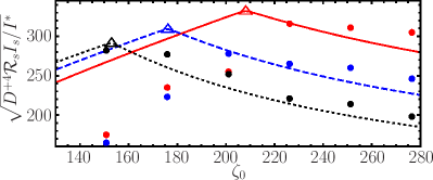
For simplicity, we first consider a driver and source pulse with one-cycle -function rise and fall, and with a five-cycle constant plateau. Figure 1 reports the maximum reflected pulse amplitude as a function of for and for . In each case the reflected pulse amplitude initially increases for increasing , reaches its maximum at , and then decreases as the Doppler factor decreases. The three triangles in Fig. 1 are centered at (, ) and their position coincides with the maximum of the reflected pulse amplitude, confirming our analytical estimates. Since in all cases , the maximum reflected amplitude rises for increasing (see Fig. 1). The results of one-dimensional (1D) PIC simulations with CP driver and the source pulses are also reported in Fig. 1 (colored circles), the foil being a slab of fully ionized carbon with . The spatial resolution is and the number of particles per cell per species . Our PIC simulation results agree with the model predictions at , i.e. at .
In a multidimensional geometry, the onset of transverse Rayleigh-Taylor-like (RT) Mulser and Bauer (2010) instabilities renders the foil ‘porous’ to the source pulse. RT instabilities in the radiation pressure acceleration regime have been investigated analytically Pegoraro and Bulanov (2007); Bulanov et al. (2009), numerically Pegoraro and Bulanov (2007); Bulanov et al. (2009); Chen et al. (2011) and experimentally Palmer et al. (2012). In particular, in Refs. Pegoraro and Bulanov (2007); Bulanov et al. (2009) it was shown that in the linear approximation the RT instability grows as with where is the wavelength of the perturbation. Our simulations indicate that in order to effectively reflect the source pulse, for Palmer et al. (2012), which can be fulfilled by increasing the value of .
In our two-dimensional (2D) PIC simulations both the driver and the source pulse have a -function temporal field profile with 15.5 fs duration (FWHM of the intensity), Gaussian transverse profile and wavelength . The driver (source) pulse is CP (LP with the electric field along the axis) with intensity () and spot radius (), corresponding to a power (). These parameters are envisaged at the APOLLON laser system Korzhimanov et al. (2011); Di Piazza et al. (2012); Chériaux et al. (2012). The foil consists of fully ionized carbon with electron density and it is initially shaped transversely with a thickness distribution , with , , and localized at . Note that the properties of such carbon foils can be engineered with high precision nowadays Krasheninnikov and Banhart (2007); van Dorp et al. (2006). It has been shown that Gaussian pulses and shaped foils can be employed to generate collimated ion beams Chen et al. (2009, 2010). Here we propose to use shaped foils to generate paraboloidal relativistic mirrors. Indeed, for the acceleration factor Chen et al. (2009) is larger in the outer part of the foil, which therefore takes a focusing profile for the source pulse. Since for many applications slow focusing and defocusing are desirable, we have set so the relativistic mirror is nearly flat before interacting with the source pulse (see Fig. 2). The size of the computational box is , the corresponding grid is and 900 particles per cell for each species are used.
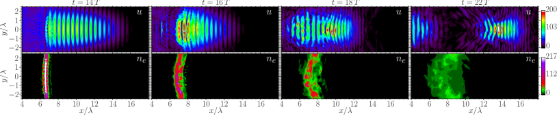
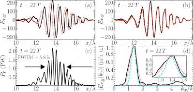
Figure 2 displays the evolution of the square root of the energy density and of the electron density distribution . The driver (source) pulse reaches the edge of the foil at (10). An accurate synchronization between two laser pulses can be achieved, e.g., by generating the two pulses from the same seed pulse before the amplification stage. Although instabilities have developed ( with our parameters) and density fluctuations are clearly visible before the source pulse impinges on the foil, the foil remains sufficiently compact to reflect the first part of the source pulse (see Fig. 2 at and the Supplemental Material [URL] for a movie of the laser-foil interaction). As the source pulse amplitude at the foil position increases, the source pulse ‘digs through’ the lower-density regions and abruptly disperses the foil, which becomes transparent to the remaining part of the pulse (see Fig. 2 from to ). Finally, at a single few-cycle reflected pulse separated from the foil remnants is observed. The peak intensity and peak power of the reflected pulse are: (for the source pulse ), and , with 5.8 fs duration and 6.8 J energy [see Fig. 3(c)]. Figure 3(a) displays the component of the electric field of the reflected pulse along the central axis for the case of zero (solid, black line) and (dotted, red line) CEP of the source pulse showing that the reflected pulse inherits the CEP of the source pulse. Inclusion of radiation reaction (RR) effects, according to Refs. Tamburini et al. (2010, 2012), does not significantly alter the reflected pulse [see Fig. 3(b)]. Our explanation is that when the reflected pulse is generated, the foil density is still high and the fields inside the foil are much smaller than in vacuum Tamburini et al. (2010). Moreover, we ensured that the probability of electron-positron pair production remains negligible. The influence of a randomly distributed preplasma on the front surface of the foil is also considered in Fig. 3(b) (dashed, red line). The preplasma thickness corresponds to 10% of the foil thickness and its average density is . The presence of the preplasma reduces the peak intensity, peak power and energy of the reflected pulse to , and 5.8 J, respectively. This can be explained by the increased electron heating due to the enhanced penetration of the driver pulse into the preplasma. The modulus of the Fourier transform of the component of the electric field along the central axis , where denotes the wave number and , is reported in Fig. 3(d) (solid, black line) showing that the reflected pulse is chirped and peaked at nm. For comparison, the spectra of two Gaussian pulses with the same wavelength and with two (dotted, red line) and three (dashed, blue line) cycles FWHM of the field profile are also reported [see Fig. 3(d)].
In order to account for the slowly-rising profile of the source pulse and estimate the wavelength and peak intensity of the reflected pulse, we approximate the -function field profile with a linearly rising profile . Here is the number of cycles before the source pulse maximum and so the source pulse and its linear profile approximation have the same duration and energy before their maximum. Assuming , the maximum reflected intensity is achieved at with . For a slowly-rising profile , thus which does not depend on the source pulse parameters. Hence, from Eq. (1) we get . By inserting our numerical parameters we obtain: and for the linearly rising profile, and and for the more realistic -function profile. While is in good agreement with the 2D simulation results, is underestimated because, by definition, the 1D model does not include focusing effects. Indeed, our simulations show that increasing the ratio by reducing from to improves the focusing and further enhances from to . In addition, higher intensities are expected in a fully 3D geometry where, in contrast to 2D simulations, the source pulse is focused also along the axis. We also mention that increasing by doubling and with the other parameters as reported on page 3 enhances to 3 PW but reduces the intensity enhancement from 2.4 to 1.8 because the pulse focusing decreases.
Finally, we stress that even a few-cycle source pulse can be further shortened and amplified. Indeed, by employing a , shaped foil and a driver (source) pulse with 15.5 fs (5.8 fs) duration, () intensity and () radius [corresponding to a driver (source) power ()], a single 1.5 cycles (2.1 fs duration), 2 J energy, PW and reflected pulse is generated (). Moreover, in contrast to the previous case of a relatively long source pulse, a 2.7 fs duration, 1.3 J energy 1 PW peak power and peak intensity transmitted pulse is also generated (see the movies in the Supplemental Material [URL]). Similar parameters for the driver and source pulses are envisaged at the Extreme Light Infrastructure Di Piazza et al. (2012); eli (2014).
Acknowledgements.
We acknowledge useful discussions with B. M. Hegelich, N. Kumar, A. Macchi and G. Sarri. We thank A. Macchi for providing his 1D PIC code. Some PIC simulations were performed using the computing resources granted by the Research Center Jülich under the project HRO01.References
- Krausz and Ivanov (2009) F. Krausz and M. Ivanov, Rev. Mod. Phys. 81, 163 (2009).
- Meuren and Di Piazza (2011) S. Meuren and A. Di Piazza, Phys. Rev. Lett. 107, 260401 (2011).
- Titov et al. (2012) A. I. Titov, H. Takabe, B. Kämpfer, and A. Hosaka, Phys. Rev. Lett. 108, 240406 (2012).
- Di Piazza et al. (2012) A. Di Piazza, C. Müller, K. Z. Hatsagortsyan, and C. H. Keitel, Rev. Mod. Phys. 84, 1177 (2012).
- Mackenroth and Di Piazza (2011) F. Mackenroth and A. Di Piazza, Phys. Rev. A 83, 032106 (2011).
- Boca et al. (2012) M. Boca, V. Dinu, and V. Florescu, Phys. Rev. A 86, 013414 (2012).
- Korzhimanov et al. (2011) A. V. Korzhimanov, A. A. Gonoskov, E. A. Khazanov, and A. M. Sergeev, Phys. Usp. 54, 9 (2011).
- Herrmann et al. (2009) D. Herrmann, L. Veisz, R. Tautz, F. Tavella, K. Schmid, V. Pervak, and F. Krausz, Opt. Lett. 34, 2459 (2009).
- Witte and Eikema (2012) S. Witte and K. Eikema, IEEE J. Sel. Topics Quantum Electron. 18, 296 (2012).
- pfs (2014) “Petawatt field synthesizer,” http://www.attoworld.de/Mainpages/Light_and_matter/index.html#42 (2014).
- Malkin et al. (1999) V. M. Malkin, G. Shvets, and N. J. Fisch, Phys. Rev. Lett. 82, 4448 (1999).
- Toroker et al. (2012) Z. Toroker, V. M. Malkin, and N. J. Fisch, Phys. Rev. Lett. 109, 085003 (2012).
- Lancia et al. (2010) L. Lancia, J.-R. Marquès, M. Nakatsutsumi, C. Riconda, S. Weber, S. Hüller, A. Mančić, P. Antici, V. T. Tikhonchuk, A. Héron, P. Audebert, and J. Fuchs, Phys. Rev. Lett. 104, 025001 (2010).
- Weber et al. (2013) S. Weber, C. Riconda, L. Lancia, J.-R. Marquès, G. A. Mourou, and J. Fuchs, Phys. Rev. Lett. 111, 055004 (2013).
- Faure et al. (2005) J. Faure, Y. Glinec, J. J. Santos, F. Ewald, J.-P. Rousseau, S. Kiselev, A. Pukhov, T. Hosokai, and V. Malka, Phys. Rev. Lett. 95, 205003 (2005).
- Schreiber et al. (2010) J. Schreiber, C. Bellei, S. P. D. Mangles, C. Kamperidis, S. Kneip, S. R. Nagel, C. A. J. Palmer, P. P. Rajeev, M. J. V. Streeter, and Z. Najmudin, Phys. Rev. Lett. 105, 235003 (2010).
- Wagner et al. (2004) N. L. Wagner, E. A. Gibson, T. Popmintchev, I. P. Christov, M. M. Murnane, and H. C. Kapteyn, Phys. Rev. Lett. 93, 173902 (2004).
- Skobelev et al. (2012) S. A. Skobelev, A. V. Kim, and O. Willi, Phys. Rev. Lett. 108, 123904 (2012).
- Vshivkov et al. (1998) V. A. Vshivkov, N. M. Naumova, F. Pegoraro, and S. V. Bulanov, Phys. Plasmas 5, 2727 (1998).
- Macchi et al. (2010) A. Macchi, S. Veghini, T. V. Liseykina, and F. Pegoraro, New J. Phys. 12, 045013 (2010).
- Macchi et al. (2009) A. Macchi, S. Veghini, and F. Pegoraro, Phys. Rev. Lett. 103, 085003 (2009).
- Mulser and Bauer (2010) P. Mulser and D. Bauer, High Power Laser-Matter Interaction, Springer Tracts in Modern Physics, Vol. 238 (Springer, 2010) Chap. 4.2.
- Esirkepov et al. (2004) T. Esirkepov, M. Borghesi, S. V. Bulanov, G. Mourou, and T. Tajima, Phys. Rev. Lett. 92, 175003 (2004).
- Thaury et al. (2007) C. Thaury, F. Quere, J.-P. Geindre, A. Levy, T. Ceccotti, P. Monot, M. Bougeard, F. Reau, P. d’Oliveira, P. Audebert, R. Marjoribanks, and P. Martin, Nature Phys. 3, 424 (2007).
- Rödel et al. (2011) C. Rödel, M. Heyer, M. Behmke, M. Kübel, O. Jäckel, W. Ziegler, D. Ehrt, M. Kaluza, and G. Paulus, Appl. Phys. B: Lasers Opt. 103, 295 (2011).
- Pegoraro and Bulanov (2007) F. Pegoraro and S. V. Bulanov, Phys. Rev. Lett. 99, 065002 (2007).
- Bulanov et al. (2009) S. V. Bulanov, T. Z. Esirkepov, F. Pegoraro, and M. Borghesi, C. R. Physique 10, 216 (2009).
- Chen et al. (2011) M. Chen, N. Kumar, A. Pukhov, and T.-P. Yu, Phys. Plasmas 18, 073106 (2011).
- Palmer et al. (2012) C. A. J. Palmer, J. Schreiber, S. R. Nagel, N. P. Dover, C. Bellei, F. N. Beg, S. Bott, R. J. Clarke, A. E. Dangor, S. M. Hassan, P. Hilz, D. Jung, S. Kneip, S. P. D. Mangles, K. L. Lancaster, A. Rehman, A. P. L. Robinson, C. Spindloe, J. Szerypo, M. Tatarakis, M. Yeung, M. Zepf, and Z. Najmudin, Phys. Rev. Lett. 108, 225002 (2012).
- Chériaux et al. (2012) G. Chériaux, F. Giambruno, A. Fréneaux, F. Leconte, L. P. Ramirez, P. Georges, F. Druon, D. N. Papadopoulos, A. Pellegrina, C. Le Blanc, I. Doyen, L. Legat, J. M. Boudenne, G. Mennerat, P. Audebert, G. Mourou, F. Mathieu, and J. P. Chambaret, AIP Conf. Proc. 1462, 78 (2012).
- Krasheninnikov and Banhart (2007) A. V. Krasheninnikov and F. Banhart, Nature Mater. 6, 723 (2007).
- van Dorp et al. (2006) W. van Dorp, C. Hagen, P. Crozier, B. van Someren, and P. Kruit, Microelectron. Eng. 83, 1468 (2006).
- Chen et al. (2009) M. Chen, A. Pukhov, T. P. Yu, and Z. M. Sheng, Phys. Rev. Lett. 103, 024801 (2009).
- Chen et al. (2010) M. Chen, T.-P. Yu, A. Pukhov, and Z.-M. Sheng, New J. Phys. 12, 045004 (2010).
- Tamburini et al. (2010) M. Tamburini, F. Pegoraro, A. Di Piazza, C. H. Keitel, and A. Macchi, New J. Phys. 12, 123005 (2010).
- Tamburini et al. (2012) M. Tamburini, T. V. Liseykina, F. Pegoraro, and A. Macchi, Phys. Rev. E 85, 016407 (2012).
- eli (2014) “Extreme light infrastructure,” http://www.eli-laser.eu/ (2014).