Infrared magneto-spectroscopy of graphite in tilted fields
Abstract
The electronic structure of Bernal-stacked graphite subject to tilted magnetic fields has been investigated using infrared magneto-transmission experiments. With the increasing in-plane component of the magnetic field , we observe significant broadening and partially also splitting of interband inter-Landau level transitions, which originate at the point of the graphite Brillouin zone, where the charge carriers behave as massless Dirac fermions. The observed behavior is attributed to the lifting of the twofold degeneracy of Landau levels at the point – a degeneracy which in graphite complements the standard spin and valley degeneracies typical of graphene.
pacs:
71.20.-b, 71.70.DiI Introduction
It was the fabrication of single-layer grapheneBerger et al. (2004); Novoselov et al. (2004) and subsequent discovery of massless Dirac fermionsNovoselov et al. (2005); Zhang et al. (2005) which triggered the present increased interest in the electrical and optical properties of graphiteLi et al. (2006); Luk’yanchuk and Kopelevich (2006); González et al. (2007); Orlita et al. (2008a, b, 2009a); Chuang et al. (2009); Zhu et al. (2010); Ubrig et al. (2011); Tung et al. (2011); Kossacki et al. (2011); Kim et al. (2012); Levallois et al. (2012) – supposedly a well-known material for the condensed matter physics.
Even though graphene is a purely two-dimensional (2D) system and graphite is characterized by a (highly anisotropic but still) clearly 3D band structure, these materials, as demonstrated experimentally,Orlita et al. (2008a, 2009a, 2009b) share surprisingly similar optical response when the magnetic field is applied perpendicularly to layers. A simple model, invoking inter-Landau level excitations between highly-degenerate Landau levels (LLs) of massless Dirac fermions, implies the magneto-optical response that is linear in , see, e.g., Refs. Sadowski et al., 2006; Gusynin et al., 2007; Jiang et al., 2007; Deacon et al., 2007; Orlita et al., 2008c; Crassee et al., 2011; I. Crassee et al., 2011; Booshehri et al., 2012, and is capable to account for a significant part of the magneto-optical data acquired on graphite. Importantly, these data come not only from recent magneto-transmission studies of thin specimens,Orlita et al. (2008a, 2009a); Chuang et al. (2009) but also from original measurements carried out in late seventies,Toy et al. (1977) in which -scaled spectral features have been observed using the magneto-reflection technique. This pioneering work is a good candidate for the first direct experimental observation of massless Dirac fermions, which in bulk graphite coexist with massive particles and which provide more conventional, i.e., linear in response.Galt et al. (1956); Schroeder et al. (1969)
The electronic band structure of graphite in the magnetic field is mostly described using the standard model proposed by Slonczewski, Weiss and McClure (SWM),Slonczewski and Weiss (1958); McClure (1960) even though presumably more precise, but at the same time, also more time-consuming approaches appeared recently, see, e.g., Refs. Ho et al., 2011a, b. The SWM model has been derived in late fifties using mostly symmetry arguments; it describes the electronic structure near the -- edge of the Brillouin zone with energies not too distant from the Fermi level. The six of seven parameters in the SWM model, ,Brandt et al. (1988) are usually interpreted as tight-binding hopping integrals between the nearest-neighbor and partially also next-nearest-neighbor atoms. An additional parameter , related to the non-equivalence of carbon atoms in A and B positions, is referred to as a pseudogap. All parameters must be considered rather as adjustable parameters than true hopping integrals and are usually obtained by fitting either experimental data or the results of ab initio calculations.Grüneis et al. (2008) The importance of individual parameters significantly varies, depending on the type of experimental data for interpretation of which the SWM model is used.
For instance, the periods of Shubnikov-de HaasWoollam (1970); Luk’yanchuk and Kopelevich (2004, 2006); Schneider et al. (2010) (SdH) and de Haas-van AlphenWilliamson et al. (1965); Schneider et al. (2012) (dHvA) oscillations depend on the extremal cross sections of the complex Fermi surface and all SWM tight-binding parameters must be properly taken into account. Similarly, cyclotron resonance experiments,Galt et al. (1956); Doezema et al. (1979); Orlita et al. (2012) which are also sensitive to the immediate vicinity of the Fermi level and which provide fairly rich response, can be hardly understood without the full SWM model.
On the other hand, interband transitions between electronic states far away from the Fermi surface can be successfully described using a simplified approach,Orlita et al. (2009a); Chuang et al. (2009) which models the magneto-optical response of bulk graphite as a sum of responses of an effective graphene bilayer and monolayer.Koshino and Ando (2008) Notably, the physical properties of a 3D system are thus described using responses of two purely 2D materials, and interestingly, not more than two coupling constants, intralayer and interlayer , are needed in the very first approach.Partoens and Peeters (2007) Within such a minimal model, the point provides response similar to a single graphene sheet, but richer due to an additional twofold degeneracy, and the point behaves as bilayer graphene, however, with the interlayer coupling enhanced twice as compared to the true bilayer. Limits of this model have been found, e.g., by revealing the electron-hole asymmetry at the point of bulk graphite in recent magneto-transmission,Chuang et al. (2009) magneto-reflectionTung et al. (2011); Levallois et al. (2012) and magneto-Raman studies.Kossacki et al. (2011); Kim et al. (2012) The full SWM model has to be used in such a case to get quantitative agreement between the experimental data and theory.
In this paper, we set other limitations of the effective monolayer and bilayer model for the magneto-optical response of graphite. Namely, we test its applicability in experiments performed in the tilted-field configuration, , which is a basic tool to distinguish between 2D and 3D character of condensed matter systems. We focus on the graphene-like signal from the point and show that the magneto-optical response of graphite in a tilted magnetic field follows the total magnetic field and not only its perpendicular component, as should be in the case of an ideal 2D system. The infrared magneto-transmission technique is thus, perhaps surprisingly, significantly more sensitive to the in-plane component of the magnetic field as compared to other techniques such as SdH or dHvA oscillations, which reveal the 3D character of graphite only for rather high tilting angles.Schneider et al. (2010, 2012) To interpret our data, we use recently developed theory of the graphite band structure subject to a tilted magnetic field, which predicts lifting of the twofold degeneracy at the point.Goncharuk and Smrčka (2012) This degeneracy, taking origin in the 3D character of graphite (four atoms in a unit cell instead of two for graphene), is an additional one to the valley and spin degeneracies in graphene.
II Experiment
Thin graphite specimens for our magneto-transmission study have been prepared by exfoliation. A thin layer of bulk graphite, with an average thickness around 100 nm, was located on the scotch tape used for exfoliation, which has several relatively wide spectral windows with a sufficiently high optical transmission. A high-quality natural graphite crystal has been chosen for exfoliation, since it provides equivalent but better pronounced magneto-optical response as compared to, e.g., highly-oriented pyrolytic graphite.Orlita et al. (2008b) The magneto-transmission spectra were measured for the magnetic field inclined with respect to the -axis of graphite by selected angles of , i.e., in the perpendicular () and several tilted-field configurations.
To measure the transmission spectra in the spectral range 100-800 meV, the non-polarized radiation of a globar was analyzed by a Fourier transform spectrometer and guided to the sample by light-pipe optics. The sample was placed in a cryostat at temperature of 2 K located inside superconducting and resistive coils, which reach magnetic fields up to 13 T and 28 T, respectively. The transmitted signal was detected by the composite Si bolometer. All spectra presented in this study have been normalized by the zero-field transmission.
III Results
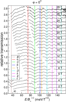
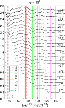
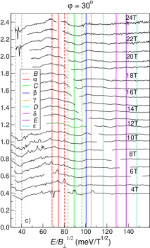
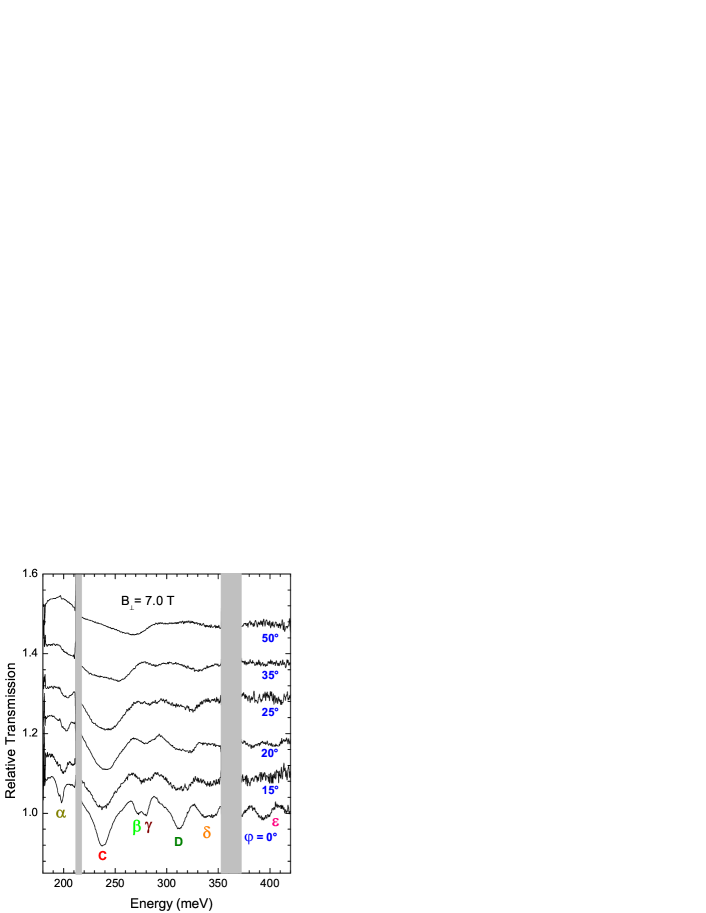
The magneto-transmission spectra measured at three different angles between the -axis of graphite and magnetic field, and 30∘, are presented in Figs. 1a-c, respectively. To facilitate identification of individual absorption lines, the transmission curves are depicted as function of the photon energy normalized by the factor of , which is typical of LLs in a system of ideal 2D massless Dirac fermions. Plotted this way, we can identify graphene-like signal originating at the point and easily follow its deviation from the dependence induced by the in-plane component of the magnetic field . An additional set of data is presented in Fig. 2, where the magneto-transmission spectra for several tilting angles are presented, all measured at a fixed perpendicular component of the field T.
The observed absorption lines have been marked consistently with the notation introduced earlier.Sadowski et al. (2006); Orlita et al. (2008a) The transitions denoted by Roman letters have their direct counterpart in the response of graphene,Sadowski et al. (2006) while the “Greek” lines are characteristic of graphite.Orlita et al. (2008a) They are, in principle, dipole-forbidden in a pure 2D system of Dirac fermions, nevertheless, they can be consistently explained with the standard dipole selection rule () when the twofold degeneracy of LLs at the points of bulk graphite is properly considered. Let us note that the widths of absorption lines reflect not only the naturally present disorder in the graphite crystal, but they are also partially given by the profile of the individual Landau subbands in the vicinity of the point.Orlita et al. (2009b)
The transmission spectra measured at , presented in Fig. 1a, are fully analogous to previous experimentsOrlita et al. (2008a, 2009a); Chuang et al. (2009) and the color vertical lines mark transmission minima proportional to . All such transitions originate at the point. The transmission minima are more pronounced at lower energies and their width increases with the increasing magnetic field. Interestingly, the number of observed transitions remains nearly constant with . This behavior reflects the specific energy dependence of the relaxation rate (i.e., broadening of lines), , which maps the (linear in energy) density of states around the point. An analogous effect has been recently observed also in graphene specimens.Orlita et al. (2011)
At a non-zero tilting angle , the observed magneto-transmission spectra significantly deviate from expectations for a purely 2D system, which is in the case of orbital effects only sensitive to the perpendicular component of the field. At as low as 15∘, see Fig. 1b, the transitions denoted by Roman letters change the shape and broaden, while the “Greek” lines become significantly weaker. For , the “Greek” lines completely disappear from spectra and also the Roman lines are much less pronounced as a result of a significant broadening. Alternatively, we can follow these effects in Fig. 2, where the magneto-transmission spectra are plotted at several angles with the perpendicular component of the field kept constant, T. The effects induced by the in-plane component of the field are well illustrated, e.g., on the C line. With increasing tilting angle, this line does not only significantly broaden, but also gains a complex structure – a strong asymmetry is developed and the line becomes nearly split into two components for higher angles ().
IV Discussion
To interpret the broadening of absorption lines with , we will consider the electronic band structure at the point of graphite in detail. In particular, we will focus on the -induced lifting of the twofold degeneracy, which in graphite complements the spin and valley degeneracies in graphene, and follow the theory recently developed by Goncharuk and Smrčka.Goncharuk and Smrčka (2012) The additional twofold degeneracy may be interpreted as a direct consequence of the effectively vanishing interlayer interaction for a charge carrier with the momentum , where is the interlayer distance. The reason is that the neighboring graphene sheets are rotated by 30∘. If the field dependence of the energy in even layers is then the energy in odd layers reads , where is the index of the LLs. Two states and belonging to degenerated eigenenergies are orthogonal and, therefore, the corresponding interlayer hopping integral is equal to zero for . In tilted fields the in-plane field component shifts the mutual position of centers of orbits and in real space by . The orbits are no longer exactly orthogonal and the interlayer interaction does not completely vanish. In the lowest order of the perturbation theory we get instead of and four energies where .Goncharuk and Smrčka (2012) Let us note that another theory presented in Ref. Pershoguba and Yakovenko, 2010 is devoted to the case of magnetic field applied strictly parallel to the sheets of the graphene bilayer and multilayers including graphite. It is suggested that the obtained energy spectrum can be verified experimentally using electron tunneling or optical spectroscopy.
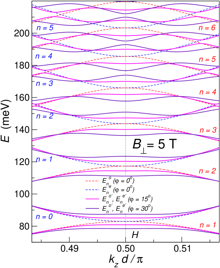
Obviously, the first order perturbation theory employed in Ref. Goncharuk and Smrčka, 2012, which involves only two states with the same energy exactly at , is not the best approximation and overestimates the splitting. It is acceptable only for rather small tilting angles and LLs with limited . For this reason, we have calculated the eigenenergies numerically employing a larger basis, which allows us to calculate also the dependence in the vicinity of the points. The results are shown in Fig. 3. Dashed lines describe the dependence of energies and in even and odd graphene sheets at . Solid lines describe the energies and , both at and , resolved by different colors. The corresponding eigenstates mix the wave functions from both even and odd layers, nevertheless, the same notation is kept to emphasize to what energies and are reduced for .
Our numerical calculations reveal the importance of the states in the vicinity of the point. Two side extrema in the dependence of energy subbands appear and the curvature of the curves is reversed at the point. Each new local extremum developed along the dependence of the energy subbands adds a new van Hove singularity to the (joint) density of states. The energy gap opened between subbands appears slightly away of the point and it decreases with the increasing LL index (). Unlike the splitting directly at the point, this energy gap of is no longer proportional to .
At , each absorption line consists of up to four degenerate transitions. To be more specific, we have two transitions for each “Greek” line and also for the B line, the rest of lines denoted by Roman letters include four degenerate transitions, with corresponding four (degenerate) van Hove singularities in the joint density of states, for details see Refs. Orlita et al., 2008a, 2009b. At , positions of these singularities are represented in Fig. 1a by the vertical color lines. The situation becomes more complex at , when the degeneracy of these four Van Hove singularities is lifted. In addition, other singularities, presumably weaker, develop in the vicinity of point. To illustrate the strength of effects induced by the in-plane magnetic field, we plot, in Figs. 1b,c, positions four main singularities in the limits of validity of the first order approximation – those which originate directly at the point. Two of them remain almost degenerate. On the other hand, for the sake of clarity, we do not mark positions of additional singularities developed due to anti-crossing of Landau subbands further from the point. To justify this, we note that such singularities in principle exist even at due to the trigonal warping term ,Nakao (1976) which is neglected in the simple effective monolayer and bilayer model. Nevertheless, they have not been observed in the experiment in perpendicular fields.Orlita et al. (2008a)
To sum up, the in-plane magnetic field profoundly modifies the profile of Landau subbands at the point of bulk graphite. A series of minigaps is created already within the first order of the perturbation theory, which is directly reflected by newly developed van Hove singularities in the joint density of states. Experimentally, this leads to the splitting of the observed dipole-allowed transitions with the increasing angle , or at least, if the disorder effects are realistically involved, to a significant broadening of these transitions. This splitting/broadening increases at the fixed roughly linearly with , or equivalently, approximatively scales as when the tilting angle is kept constant. Such behavior is consistent with the experimental data plotted in Fig. 2 and in Figs. 1a-c, respectively.
V Conclusions
The electronic band structure at the point of bulk graphite has been studied using the infrared transmission technique in magnetic fields tilted with respect to the -axis of this material. While for the magnetic field applied along this axis, the magneto-optical responses of graphite (due to the point) and graphene (due to the point) closely resemble each other, pronounced deviations clearly appear with the increasing tilting angle. The 3D nature of the electronic band structure of bulk graphite is thus revealed at significantly lower tilting angles as compared to SdH and dHvA measurements.Schneider et al. (2010, 2012)
Acknowledgements.
We thank to M. Potemski for valuable discussions. The support of the European Science Foundation EPIGRAT project (GRA/10/E006), GACR No. P204/10/1020, programme “Transnational access” contract No. 228043-EuroMagNET II-Integrated Activities, AVCR research program AVOZ10100521, the Academy of Sciences of the Czech Republic project KAN400100652 and the fund No. SVV-2012-265306 via the Charles University in Prague are acknowledged.References
- Berger et al. (2004) C. Berger, Z. Song, T. Li, X. Li, A. Y. Ogbazghi, R. Feng, Z. Dai, A. N. Marchenkov, E. H. Conrad, P. N. First, and W. A. de Heer, J. Phys. Chem. B 108, 19912 (2004).
- Novoselov et al. (2004) K. S. Novoselov, A. K. Geim, S. Morozov, D. Jiang, M. I. Katsnelson, I. Grigorieva, S. Dubonos, and A. A. Firsov, Science 306, 666 (2004).
- Novoselov et al. (2005) K. S. Novoselov, A. K. Geim, S. V. Morozov, D. Jiang, M. I. Katsnelson, I. V. Grigorieva, S. V. Dubonos, and A. A. Firsov, Nature 438, 197 (2005).
- Zhang et al. (2005) Y. Zhang, Y.-W. Tan, H. L. Stormer, and P. Kim, Nature 438, 201 (2005).
- Li et al. (2006) Z. Q. Li, S.-W. Tsai, W. J. Padilla, S. V. Dordevic, K. S. Burch, Y. J. Wang, and D. N. Basov, Phys. Rev. B 74, 195404 (2006).
- Luk’yanchuk and Kopelevich (2006) I. A. Luk’yanchuk and Y. Kopelevich, Phys. Rev. Lett. 97, 256801 (2006).
- González et al. (2007) J. C. González, M. Munoz, , N. García, J. Barzola-Quiquia, D. Spoddig, K. Schindler, , and P. Esquinazi, Phys. Rev. Lett. 99, 216601 (2007).
- Orlita et al. (2008a) M. Orlita, C. Faugeras, G. Martinez, D. K. Maude, M. L. Sadowski, and M. Potemski, Phys. Rev. Lett. 100, 136403 (2008a).
- Orlita et al. (2008b) M. Orlita, C. Faugeras, G. Martinez, D. K. Maude, M. L. Sadowski, J. M. Schneider, and M. Potemski, J. Phys.: Condens. Mat. 20, 454223 (2008b).
- Orlita et al. (2009a) M. Orlita, C. Faugeras, J. M. Schneider, G. Martinez, D. K. Maude, and M. Potemski, Phys. Rev. Lett. 102, 166401 (2009a).
- Chuang et al. (2009) K.-C. Chuang, A. M. R. Baker, and R. J. Nicholas, Phys. Rev. B 80, 161410 (2009).
- Zhu et al. (2010) Z. Zhu, H. Yang, B. Fauqué, Y. Kopelevich, and K. Behnia, Nature Phys. 6, 26 (2010).
- Ubrig et al. (2011) N. Ubrig, P. Plochocka, P. Kossacki, M. Orlita, D. K. Maude, O. Portugall, and G. L. J. A. Rikken, Phys. Rev. B 83, 073401 (2011).
- Tung et al. (2011) L. C. Tung, P. Cadden-Zimansky, J. Qi, Z. Jiang, and D. Smirnov, Phys. Rev. B 84, 153405 (2011).
- Kossacki et al. (2011) P. Kossacki, C. Faugeras, M. Kühne, M. Orlita, A. A. L. Nicolet, J. M. Schneider, D. M. Basko, Y. I. Latyshev, and M. Potemski, Phys. Rev. B 84, 235138 (2011).
- Kim et al. (2012) Y. Kim, Y. Ma, A. Imambekov, N. G. Kalugin, A. Lombardo, A. C. Ferrari, J. Kono, and D. Smirnov, Phys. Rev. B 85, 121403 (2012).
- Levallois et al. (2012) J. Levallois, M. Tran, and A. B. Kuzmenko, Solid State Communications 152, 1294 (2012).
- Orlita et al. (2009b) M. Orlita, C. Faugeras, G. Martinez, D. K. Maude, J. M. Schneider, M. Sprinkle, C. Berger, W. A. de Heer, and M. Potemski, Solid State Commun. 149, 1128 (2009b).
- Sadowski et al. (2006) M. L. Sadowski, G. Martinez, M. Potemski, C. Berger, and W. A. de Heer, Phys. Rev. Lett. 97, 266405 (2006).
- Gusynin et al. (2007) V. P. Gusynin, S. G. Sharapov, and J. P. Carbotte, Phys. Rev. Lett. 98, 157402 (2007).
- Jiang et al. (2007) Z. Jiang, E. A. Henriksen, L. C. Tung, Y.-J. Wang, M. E. Schwartz, M. Y. Han, P. Kim, and H. L. Stormer, Phys. Rev. Lett. 98, 197403 (2007).
- Deacon et al. (2007) R. S. Deacon, K.-C. Chuang, R. J. Nicholas, K. S. Novoselov, and A. K. Geim, Phys. Rev. B 76, 081406R (2007).
- Orlita et al. (2008c) M. Orlita, C. Faugeras, P. Plochocka, P. Neugebauer, G. Martinez, D. K. Maude, A.-L. Barra, M. Sprinkle, C. Berger, W. A. de Heer, and M. Potemski, Phys. Rev. Lett. 101, 267601 (2008c).
- Crassee et al. (2011) I. Crassee, J. Levallois, A. L. Walter, M. Ostler, A. Bostwick, E. Rotenberg, T. Seyller, D. van der Marel, and A. B. Kuzmenko, Nature Phys. 7, 48 (2011).
- I. Crassee et al. (2011) I. Crassee et al., Phys. Rev. B 84, 035103 (2011).
- Booshehri et al. (2012) L. G. Booshehri, C. H. Mielke, D. G. Rickel, S. A. Crooker, Q. Zhang, L. Ren, E. H. Hároz, A. Rustagi, C. J. Stanton, Z. Jin, Z. Sun, Z. Yan, J. M. Tour, and J. Kono, Phys. Rev. B 85, 205407 (2012).
- Toy et al. (1977) T. W. W. Toy, M. S. Dressehaus, and G. Dresselhaus, Phys. Rev. B 15, 4077 (1977).
- Galt et al. (1956) J. K. Galt, W. A. Yager, and H. W. Dail, Phys. Rev. 103, 1586 (1956).
- Schroeder et al. (1969) P. R. Schroeder, M. S. Dresselhaus, and A. Javan, Phys. Rev. Lett. 20, 1292 (1969).
- Slonczewski and Weiss (1958) J. C. Slonczewski and P. R. Weiss, Phys. Rev. 109, 272 (1958).
- McClure (1960) J. W. McClure, Phys. Rev. 119, 606 (1960).
- Ho et al. (2011a) Y.-H. Ho, Y.-H. Chiu, W.-P. Su, and M.-F. Lin, Applied Physics Letters 99, 011914 (2011a).
- Ho et al. (2011b) Y. H. Ho, J. Wang, Y. H. Chiu, M. F. Lin, and W. P. Su, Phys. Rev. B 83, 121201 (2011b).
- Brandt et al. (1988) N. B. Brandt, S. M. Chudinov, and Y. G. Ponomarev, Semimetals 1: Graphite and its Compounds, Modern Problems in Condensed Matter Sciences, Vol. 20.1 (North-Holland, Amsterdam, 1988).
- Grüneis et al. (2008) A. Grüneis, C. Attaccalite, L. Wirtz, H. Shiozawa, R. Saito, T. Pichler, and A. Rubio, Phys. Rev. B 78, 205425 (2008).
- Woollam (1970) J. A. Woollam, Phys. Rev. Lett. 25, 810 (1970).
- Luk’yanchuk and Kopelevich (2004) I. A. Luk’yanchuk and Y. Kopelevich, Phys. Rev. Lett. 93, 166402 (2004).
- Schneider et al. (2010) J. M. Schneider, N. A. Goncharuk, P. Vašek, P. Svoboda, Z. Výborný, L. Smrčka, M. Orlita, M. Potemski, and D. K. Maude, Phys. Rev. B 81, 195204 (2010).
- Williamson et al. (1965) S. J. Williamson, S. Foner, and M. S. Dresselhaus, Phys. Rev. 140, A1429 (1965).
- Schneider et al. (2012) J. M. Schneider, B. A. Piot, I. Sheikin, and D. K. Maude, Phys. Rev. Lett. 108, 117401 (2012).
- Doezema et al. (1979) R. E. Doezema, W. R. Datars, H. Schaber, and A. Van Schyndel, Phys. Rev. B 19, 4224 (1979).
- Orlita et al. (2012) M. Orlita, P. Neugebauer, C. Faugeras, A.-L. Barra, M. Potemski, F. M. D. Pellegrino, and D. M. Basko, Phys. Rev. Lett. 108, 017602 (2012).
- Goncharuk and Smrčka (2012) N. A. Goncharuk and L. Smrčka, Journal of Physics: Condensed Matter 24, 185503 (2012).
- Koshino and Ando (2008) M. Koshino and T. Ando, Phys. Rev. B 77, 115313 (2008).
- Partoens and Peeters (2007) B. Partoens and F. M. Peeters, Phys. Rev. B 75, 193402 (2007).
- Orlita et al. (2011) M. Orlita, C. Faugeras, R. Grill, A. Wysmolek, W. Strupinski, C. Berger, W. A. de Heer, G. Martinez, and M. Potemski, Phys. Rev. Lett. 107, 216603 (2011).
- Pershoguba and Yakovenko (2010) S. S. Pershoguba and V. M. Yakovenko, Phys. Rev. B 82, 205408 (2010).
- Nakao (1976) K. Nakao, J. Phys. Soc. Jpn. 40, 761 (1976).