Driving phase slips in a superfluid atom circuit with a rotating weak link
Abstract
We have observed well-defined phase slips between quantized persistent current states around a toroidal atomic (23Na) Bose-Einstein condensate. These phase slips are induced by a weak link (a localized region of reduced superfluid density) rotated slowly around the ring. This is analogous to the behavior of a superconducting loop with a weak link in the presence of an external magnetic field. When the weak link is rotated more rapidly, well-defined phase slips no longer occur, and vortices enter into the bulk of the condensate. A noteworthy feature of this system is the ability to dynamically vary the current-phase relation of the weak link, a feature which is difficult to implement in superconducting or superfluid helium circuits.
Many quantum fluids exhibit superfluid phenomena, including dissipationless flow and persistent circulation. Furthermore, a quantum fluid interrupted by a weak link (e.g., a Josephson junction) can act as a nonlinear interferometer, allowing the creation of highly sensitive detectors such as SQUID magnetometers Clarke and Braginski (2004) and superfluid helium gyroscopes Packard and Vitale (1992); Schwab et al. (1997); Avenel et al. (1997); Simmonds et al. (2001); Hoskinson et al. (2006); Sato and Packard (2012). Ultracold atomic gases offer new opportunities for control and measurement Leggett (2006), and it is now becoming possible to realize ultracold atomic “circuits” in configurations analogous to those mentioned above Ramanathan et al. (2011). Such devices provide opportunities for refining our understanding of flow and dissipation in quantum fluids, and may also prove useful for inertial sensing.
Several experiments with ultracold atomic gases in simply-connected geometries have observed a critical velocity for dissipation when a defect is moved through the system Raman et al. (1999); Onofrio et al. (2000); Inouye et al. (2001); Engels and Atherton (2007); Miller et al. (2007); Neely et al. (2010); Desbuquois et al. (2012). Other experiments have observed Josephson effects across a thin barrier Albiez et al. (2005); Levy et al. (2007); LeBlanc et al. (2011). More recent experiments with Bose-Einstein condensates in multiply-connected geometries have demonstrated persistent currents Ryu et al. (2007), the stochastic decay of persistent currents in a series of quantized steps Moulder et al. (2012), and phase slips across a stationary weak link Ramanathan et al. (2011).
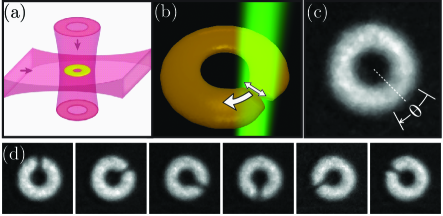
In this Letter, we demonstrate deterministic phase slips between quantized circulation states, caused by rotating a weak link around a toroidal (i.e. annular) condensate (see Fig. 1). In the rotating frame, the response of the system is analogous to that of a static superconducting ring, with a Josephson junction, in an external magnetic field. In this analogy, the quantized circulation of the superfluid corresponds to magnetic flux, and the rotation of the barrier corresponds to an external magnetic field. Rotation of the barrier causes a supercurrent to flow through it. This flow is dissipationless below some critical current , leaving the quantized circulation state in the ring unchanged. At a high enough rotation rate exceeds , and excitations can occur. For some circuit parameters, these excitations lead to a change in circulation state via a discontinuous jump in the phase of the condensate wavefunction, i.e., a phase slip Avenel and Varoquaux (1985, 1988); Amar et al. (1992). Increasing the rotation rate again until exceeds will cause another phase slip. The sharp change of circulation (or magnetic flux) in the ring in response to rotation (or magnetic field) is the key to the exceptional sensitivity of devices such as SQUID magnetometers Clarke and Braginski (2004) and superfluid helium gyroscopes Sato and Packard (2012).
The superfluid state of the condensate is given by , where is the superfluid density, and is the phase. In an inertial frame is related to the superfluid velocity by , where is Planck’s constant and is the atomic mass. The circulation around any closed path, , must be quantized according to the Bohr-Sommerfeld rule, , where is the integer winding number of the circulation, and . In a ring geometry without a barrier, this gives rise to a series of metastable persistent current states, with the ground state having .
When two bulk coherent regions are coupled by a tunnel junction, the current is a periodic function of the phase difference across the junction Clarke and Braginski (2004). Even non-tunnel coupling can lead to single-valued and periodic current-phase relations under certain circumstances Likharev (1979). The weak link in our experiments is not a tunnel junction; in the direction of flow it is thick compared to the condensate healing length, and is more analogous to a superconducting constriction (e.g., Dayem bridge) Anderson and Dayem (1964). The current-phase relation in such a geometry is in general not single-valued or periodic, but can become so when the peak height of the barrier potential, , is on the order of the condensate chemical potential, Baratoff et al. (1970); Deaver and Pierce (1972); Piazza et al. (2010). As discussed below, our present data are consistent with the current-phase relation of an ideal Josephson junction in series with a small linear inductance.
We create condensates of 23Na atoms in a toroidal optical dipole trap Ramanathan et al. (2011) (see Fig. 1a). The radius of the ring-shaped potential minimum, which coincides with the peak atomic density, is determined by absorption imaging to be m end (a). The radial Thomas-Fermi half-width of the annulus is m. We estimate the vertical half-width to be m using the measured vertical trap frequency of 600(5) Hz and a calculated chemical potential kHz. The azimuthal variation of the trap depth is of , resulting in the nearly uniform density profile shown in Fig. 1(c). The condensate is initially formed in a non-rotating state end (b).
The rotating weak link was created by a focused, blue-detuned laser field, which caused the atoms to experience a localized (optical dipole) force repelling them from the beam. The focus was a spot m in diameter (FWHM), which was moved along a chosen trajectory in the plane of the ring, using a 2-axis acousto-optic deflector. Rapid scanning of the spot allows us to create effective time-averaged optical potentials Henderson et al. (2009). In this experiment we created a wide, flat barrier by scanning the radial position of the spot across the condensate as a triangle-wave, with a scan amplitude greater than 2 (see Fig. 1b). We rotated this time-averaged barrier azimuthally for 1.5 s at constant 3 Hz, which is the angular frequency of sound propagating around the ring. During the first 0.5 s, the strength of the barrier potential was increased linearly to a value . It was then held constant for 0.5 s, and finally ramped off over the last 0.5 s. To minimize systematic effects due to variations in the effective around the ring, we determined the region of lowest density and centered the barrier trajectory over this region (Fig. 1(c)).
The critical current through the weak link, , is reached when the superfluid velocity becomes equal to the critical velocity Ramanathan et al. (2011); Watanabe et al. (2009). Increasing the barrier height reduces the local superfluid density, decreasing the critical current. The ability to dynamically vary the strength of the weak link and its current-phase relation is an advantageous feature of this atom circuit, potentially allowing for “third-terminal” functionality that is difficult to achieve in superconducting circuits Baselmans et al. (1999); Bell et al. (2003); Nevirkovets et al. (2007).
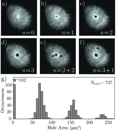
To determine the circulation state of the condensate, we released it from the trap, allowing it to expand in time-of-flight (TOF). We then imaged the condensate, looking perpendicular to the plane of the ring. A condensate in a non-circulating state expands into a smooth density profile that is peaked at the center, as shown in Fig. 2(a).
Circulation in the condensate manifests itself in two different ways. A pure persistent current state exhibits azimuthal flow around the ring, with no vortex core present in the annulus. In TOF, this results in a single central hole with a size that increases with the winding number of the current around the ring, as shown in Fig. 2(b-d). At high rotation rates, vortices are expected Donnelly and Fetter (1966); Fetter (1967) to enter the annular region and can remain there, appearing as off-center holes in the TOF density profile. These are distinguishable from the central hole caused by a persistent current, as shown in Fig. 2(e,f).
The histogram in Fig. 2(f) shows the central hole size distribution end (c) for the data in Fig. 3, comprising 727 experimental runs. The quantization of circulation is evident from the peaking of the distribution about a series of values, as has been previously noted Henderson et al. (2009); Moulder et al. (2012). The width of the peaks is due to variation in the TOF expansion dynamics, primarily caused by shot-to-shot atom number fluctuations. Annular vortices are not stable in the absence of the rotating barrier, and leave the annulus on a time scale that depends on the condensate temperature, the trap geometry, and trap smoothness Fedichev and Shlyapnikov (1999); Abo-Shaeer et al. (2002). Under the conditions of our experiment, the measured lifetime of these annular vortices is about 3 seconds, therefore an annular vortex formed during our 1.5 second stirring procedure is likely to be present during TOF imaging.
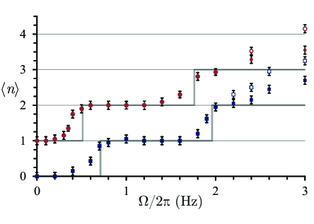
Using the TOF images, we can determine the change in circulation caused by the barrier rotating at a given angular frequency . Figure 3 shows the response of the condensate to the rotating barrier for two barrier heights. The lower data set is for a , the upper data set is for a barrier height 14(2)% higher. For each and , we repeated the experiment at least 20 times, and averaged the measured winding numbers . For small the condensate is unperturbed, and after the stirring procedure. As increases, the average winding number changes from 0 to 1. The value of remains 1 up to a higher angular frequency, where a transition to occurs. A comparison of the two data sets shows that by varying the barrier height we can adjust the critical current . In particular, a lower corresponds to a higher , i.e. a higher critical .
To model our experiment, we consider a 1D system in a frame co-rotating with the weak link. In this rotating frame, the superfluid velocity is , and the Bohr-Sommerfeld quantization condition is
| (1) |
Here is the external “circulation flux” due to rotation at angular velocity , is the kinetic/hydrodynamic inductance of the ring, excluding the junction Kadin (1999); Sato and Packard (2012), is the circumference of the ring minus the effective length of the junction, and is the mass per unit length around the ring, which is assumed constant outside the barrier region. is the mass current in the rotating frame. The terms on the right of Eq. (1) are, respectively, the Sagnac phase due to the rotating frame, the change in phase due to current around the ring, and the phase drop across the weak link. The last term is determined by the current-phase relation of the weak link, which we approximate as an ideal sinusoidal current-phase relation plus a small linear kinetic inductance Deaver and Pierce (1972); Baratoff et al. (1970); Piazza et al. (2010):
| (2) |
We combine equations (1) and (2) and obtain
| (3) |
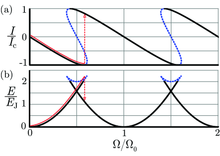
The parameter is the ratio of the total hydrodynamic inductance to the (fluid) Josephson inductance of the weak link . Figure 4(a) is a normalized plot of as implicitly defined by Eqn. (3), with , which is in the hysteretic regime end (e), and approximates the conditions of our experiment for = 0.5 . The circulation energy, , can be written as Tin :
| (4) |
where is the Josephson energy of the weak link. Equations (3) and (4) implicitly define , plotted in Fig. 4(b), with . For each value of the winding number , the stable branches (solid lines) continue up to . Above this point, the system becomes dynamically unstable and dissipation can occur (dashed lines). At this point in the plots of Fig. 4, there is a state of different with lower total energy, and a phase slip occurs, taking the system to that state. The critical angular frequency at which a phase slip occurs to is found by setting in Eqn. (3), and solving for :
| (5) |
where . The solid grey lines in Fig. 3 show the values of for , for (vertically offset) and (lower), both with Hz. These values of were chosen to match the observed phase slips, and are consistent with calculated estimates of and . As seen, decreasing increases and , causing to increase.
While the data show a clear signature of a phase slip from to , the response of the condensate is different at higher . We attribute this to the fact that we have a wide () annulus. At higher , the velocity mismatch between the irrotational flow () at the inner and outer edges and the rotating frame () makes it energetically favorable for annular vortices to appear Donnelly and Fetter (1966); Fetter (1967). This is consistent with what we observe for Hz, as shown in Fig. 2(e,f). The presence of annular vortices allows the winding number to depend on the path . In particular, the difference in winding numbers at the inner and outer edges of the annulus equals the number of vortices in the annulus. This effect is reflected in the difference between the open and closed symbols of Fig. 3. The appearance of annular vortices is analogous to the penetration of flux lines into a type-II superconductor Anderson and Kim (1964); Fetter (1967). The non-negligible width of the annulus also necessitates a correction to the effective radius of the ring, and therefore to . For a parabolic radial density profile with the dimensions of our trap, the correction factor is sup (b). This gives an effective Hz.
In conclusion, we have deterministically driven single phase slips between circulation states in an atom circuit with a rotating weak link. This circuit is an atomic analog of a single-junction DC SQUID. The behavior of the circuit is consistent with a model assuming a periodic current-phase relation for the weak link. Furthermore, by varying the barrier height, we have shown that the junction critical current can be controlled experimentally.
Other phenomena characteristic of superconducting circuits should also be observable in atomic circuits. Since rotation in our system is analogous to magnetic field in a SQUID, our device represents a proof-of principle BEC rotation sensor. Additional interesting examples include hysteresis, sensitivity to thermal effects, Shapiro steps, and multi-junction devices. Our ability to dynamically change the current-phase relation may even lead to new functionality in controlling atom circuits.
The authors thank L. Mathey, A. Mathey, C. Clark, and M. Edwards for insightful discussions, J. G. Lee and Y. Shyur for technical assistance, and S. E. Shafranjuk and M. Blamire for providing valuable information on three-terminal superconducting devices. This work was partially supported by ONR, the ARO atomtronics MURI, and the NSF PFC at JQI. CJL acknowledges support from the NIST-ARRA program.
References
- Clarke and Braginski (2004) J. Clarke and A. I. Braginski, The SQUID Handbook, vol. 1,2 (Wiley-VCH, Weinheim, 2004).
- Packard and Vitale (1992) R. E. Packard and S. Vitale, Phys. Rev. B 46, 3540 (1992).
- Schwab et al. (1997) K. Schwab, N. Bruckner, and R. E. Packard, Nature 386, 585 (1997).
- Avenel et al. (1997) O. Avenel, P. Hakonen, and E. Varoquaux, Phys. Rev. Lett. 78, 3602 (1997).
- Simmonds et al. (2001) R. W. Simmonds, A. Marchenkov, E. Hoskinson, J. C. Davis, and R. E. Packard, Nature 412, 55 (2001).
- Hoskinson et al. (2006) E. Hoskinson, Y. Sato, and R. Packard, Phys. Rev. B 74, 100509 (2006).
- Sato and Packard (2012) Y. Sato and R. E. Packard, Rep. Prog. Phys. 75, 016401 (2012).
- Leggett (2006) A. J. Leggett, Quantum Liquids (Oxford University Press, 2006).
- Ramanathan et al. (2011) A. Ramanathan, K. C. Wright, S. R. Muniz, M. Zelan, W. T. Hill, C. J. Lobb, K. Helmerson, W. D. Phillips, and G. K. Campbell, Phys. Rev. Lett. 106, 130401 (2011).
- Raman et al. (1999) C. Raman, M. Köhl, R. Onofrio, D. Durfee, C. Kuklewicz, Z. Hadzibabic, and W. Ketterle, Phys. Rev. Lett. 83, 2502 (1999).
- Onofrio et al. (2000) R. Onofrio, C. Raman, J. M. Vogels, J. R. Abo-Shaeer, A. P. Chikkatur, and W. Ketterle, Phys. Rev. Lett. 85, 2228 (2000).
- Inouye et al. (2001) S. Inouye, S. Gupta, T. Rosenband, A. P. Chikkatur, A. Görlitz, T. L. Gustavson, A. E. Leanhardt, D. E. Pritchard, and W. Ketterle, Phys. Rev. Lett. 87, 080402 (2001).
- Engels and Atherton (2007) P. Engels and C. Atherton, Phys. Rev. Lett. 99, 160405 (2007).
- Miller et al. (2007) D. E. Miller, J. K. Chin, C. A. Stan, Y. Liu, W. Setiawan, C. Sanner, and W. Ketterle, Phys. Rev. Lett. 99, 070402 (2007).
- Neely et al. (2010) T. W. Neely, E. C. Samson, A. S. Bradley, M. J. Davis, and B. P. Anderson, Phys. Rev. Lett. 104, 160401 (2010).
- Desbuquois et al. (2012) R. Desbuquois, L. Chomaz, T. Yefsah, J. Leonard, J. Beugnon, C. Weitenberg, and J. Dalibard, Nat. Phys. 8, 645 (2012).
- Albiez et al. (2005) M. Albiez, R. Gati, J. Fölling, S. Hunsmann, M. Cristiani, and M. K. Oberthaler, Phys. Rev. Lett. 95, 010402 (2005).
- Levy et al. (2007) S. Levy, E. Lahoud, I. Shomroni, and J. Steinhauer, Nature 449, 579 (2007).
- LeBlanc et al. (2011) L. J. LeBlanc, A. B. Bardon, J. McKeever, M. H. T. Extavour, D. Jervis, J. H. Thywissen, F. Piazza, and A. Smerzi, Phys. Rev. Lett. 106, 025302 (2011).
- Ryu et al. (2007) C. Ryu, M. F. Andersen, P. Cladé, V. Natarajan, K. Helmerson, and W. D. Phillips, Phys. Rev. Lett. 99, 260401 (2007).
- Moulder et al. (2012) S. Moulder, S. Beattie, R. P. Smith, N. Tammuz, and Z. Hadzibabic, Phys. Rev. A 86, 013629 (2012).
- Avenel and Varoquaux (1985) O. Avenel and E. Varoquaux, Phys. Rev. Lett. 55, 2704 (1985).
- Avenel and Varoquaux (1988) O. Avenel and E. Varoquaux, Phys. Rev. Lett. 60, 416 (1988).
- Amar et al. (1992) A. Amar, Y. Sasaki, R. L. Lozes, J. C. Davis, and R. E. Packard, Phys. Rev. Lett. 68, 2624 (1992).
- Likharev (1979) K. K. Likharev, Rev. Mod. Phys. 51, 101 (1979).
- Anderson and Dayem (1964) P. W. Anderson and A. H. Dayem, Phys. Rev. Lett. 13, 195 (1964).
- Baratoff et al. (1970) A. Baratoff, J. A. Blackburn, and B. B. Schwartz, Phys. Rev. Lett. 25, 1096 (1970).
- Deaver and Pierce (1972) B. Deaver, Jr. and J. Pierce, Phys. Lett. A 38, 81 (1972).
- Piazza et al. (2010) F. Piazza, L. A. Collins, and A. Smerzi, Phys. Rev. A 81, 033613 (2010).
- end (a) Uncertainties herein are the uncorrelated combination of 1 statistical and systematic uncertainties unless stated otherwise.
- end (b) The measured probability of spontaneous vortex formation was consistent with zero ( 5%, with a 95% confidence interval).
- Henderson et al. (2009) K. Henderson, C. Ryu, C. MacCormick, and M. G. Boshier, New J. Phys. 11, 043030 (2009).
- Watanabe et al. (2009) G. Watanabe, F. Dalfovo, F. Piazza, L. P. Pitaevskii, and S. Stringari, Phys. Rev. A 80, 053602 (2009).
- Baselmans et al. (1999) J. J. A. Baselmans, A. F. Morpurgo, B. J. van Wees, and T. M. Klapwijk, Nature 397, 43 (1999).
- Bell et al. (2003) C. Bell, G. Burnell, L. C. W., E. J. Tarte, K. D.-J., and M. G. Blamire, Applied Physics Letters 84, 1153 (2003).
- Nevirkovets et al. (2007) I. P. Nevirkovets, S. E. Shafranjuk, O. Chernyashevskyy, and J. B. Ketterson, Phys. Rev. B 76, 184520 (2007).
- sup (a) See Supplemental Material at [url] for a description of the time-of-flight image analysis.
- Donnelly and Fetter (1966) R. J. Donnelly and A. L. Fetter, Phys. Rev. Lett. 17, 747 (1966).
- Fetter (1967) A. L. Fetter, Phys. Rev. 153, 285 (1967).
- end (c) If a condensate with is released directly from the annular trap, the size of this central hole remains below our imaging resolution for experimentally accessible TOFs ( ms). To make the hole visible in short TOF, we adiabatically relax the radial confinement by reducing the ring beam intensity by 90 over 150 ms, just before release into TOF (see Ref. [8]).
- Fedichev and Shlyapnikov (1999) P. O. Fedichev and G. V. Shlyapnikov, Phys. Rev. A 60, R1779 (1999).
- Abo-Shaeer et al. (2002) J. R. Abo-Shaeer, C. Raman, and W. Ketterle, Phys. Rev. Lett. 88, 070409 (2002).
- end (d) For all , we use a constant value = 1/2 (the maximum standard deviation of a Bernoulli-distributed variable) as an upper-bound estimate of the standard deviation of , and estimate the standard error of as .
- Kadin (1999) A. M. Kadin, Introduction to Superconducting Circuits (John Wiley and Sons, New York, 1999).
- end (e) For there are values of for which there are no stable solutions, and dissipation can occur without leading to a well-defined phase slip. For there is a stable solution for all . In general, hysteretic behavior can occur for .
- (46) This equation is equivalent to the energy of a radio-frequency SQUID, see M. Tinkham, Introduction to Superconductivity, 2nd. Edition, 1996, McGraw-Hill, New York, p. 230.
- Anderson and Kim (1964) P. W. Anderson and Y. B. Kim, Rev. Mod. Phys. 36, 39 (1964).
- sup (b) See Supplemental Material at [url] for a calculation of this correction factor.