Surface enhanced circular dichroism spectroscopy mediated by non-chiral nanoantennas
Abstract
We theoretically investigate light-matter interactions for chiral molecules in the presence of non-chiral nanoantennas. Isotropic nanostructures supporting optical-frequency electric or magnetic dipoles are sufficient to locally enhance the excitation of a molecule’s chiral polarizability and thus its circular dichroism spectrum. However, simultaneous electric and magnetic dipoles are necessary to achieve a net, spatially-averaged enhancement. Our contribution provides a theoretical framework to understand chiral light-matter interactions at the nanoscale and sets the necessary and sufficient conditions to enhance circular dichroism spectroscopy in the presence of nanoantennas. The results may lead to new, field-enhanced, chiral spectroscopic techniques.
pacs:
78.30.-j, 33.70.-w, 73.22.Lp, 84.40.BaChiral objects - those whose mirror images are not superimposable - abound in nature. Examples range from spiral galaxies to human hands to nucleic acids. Chirality is fundamental to many biological, chemical, and physical processes: it can contribute to the gene flow and evolution of snail colonies Ueshima and Asami (2003), determine the effectiveness of pharmaceutical drugs, and impact the formation of fermionic condensates and superfluids. Nature’s preference for a certain chirality, e.g. the fact that all proteins form a left-handed spiral while sugars twist to the right, constitutes one of life’s greatest mysteries Hegstrom and Kondepudi (1990).
In electromagnetism, circularly-polarized light (CPL) is the paradigmatic example of a chiral field. Propagating in a dispersion-less medium, the electric and magnetic fields of CPL undergo one full rotation per period and wavelength. This rotation can be either clockwise or counter-clockwise. The spatial trajectories of these two waves form a chiral set of solutions to Maxwell’s equations.
Circularly polarized light can be used to probe the geometric and electromagnetic chiral properties of molecules. A specific enantiomer of a chiral molecule will exhibit a preferential absorption of right or left-handed circularly polarized light. Circular dichroism (CD) spectroscopy measures this differential absorption in the ultraviolet and visible spectrum, while vibrational circular dichroism (VCD) extends the technique to the infrared Barron (2004). Both CD and VCD are highly valuable techniques: for example, in molecular biology, they elucidate a protein’s secondary structure, which in turn provides insight into the protein’s function. In pharmacology, these techniques determine the chiral purity of chemical products and the absolute structure of pure enantiomers Rodger (2006); Polavarapu and Zhao (2000).
Despite the wide applicability of CD and VCD, their sensitivity is limited. Proteins and nucleic acids exhibit a differential absorption of left and right circularly polarized light which is nearly five orders of magnitude less than their absorption of unpolarized light. Hence, in order to get measurable signals, large sample concentrations or signal amplifiers are needed. This prohibits CD and VCD spectroscopy from entering the few molecule regime.
In recent years, engineered light-matter interactions at the nanoscale have enhanced the sensitivity of other spectroscopic techniques such as Surface Enhanced Raman Spectroscopy (SERS) and Surface-Enhanced Infra-Red Absorption spectroscopy (SEIRA). Nanostructured surfaces and nanoparticles supporting strong optical-frequency electric resonances have allowed SERS and SEIRA to reach single molecule and attomolar sensitivity, respectively Nie and Emory (1997); Kneipp et al. (1997); Xu et al. (1999); Neubrech et al. (2008). In this paper, drawing on insights from SERS and SEIRA, we investigate the fundamental electromagnetic conditions necessary to increase the sensitivity of CD and VCD spectroscopy. Since chiral molecules are characterized by electric and magnetic dipoles, enhancing (V)CD spectroscopy requires control over both the electric and magnetic fields of light. Accordingly, attention is given to nanostructures supporting either electric or magnetic resonances, or both. We show that molecules near an electrically- or magnetically-resonant nanoparticle will experience a local, position-dependent chiral enhancement. Averaged over all space, such electrically- or magnetically-resonant nanoparticles do not produce a net enhancement of the (V)CD signal. In contrast, engineered nanostructures with combined electric and magnetic resonances do produce a global enhancement of the signal. Our results determine the necessary and sufficient conditions required to enhance chiral light-matter interactions, and may enable new spectroscopic techniques such as field enhanced circular dichroism or field enhanced vibrational circular dichroism.
To describe the excitation of chiral molecules by electric and magnetic fields of arbitrary polarization states, we adopt the formalism introduced by Tang and Cohen Tang and Cohen (2010, 2011). In general, we assume that a circularly polarized plane wave illuminates a nanoparticle, and that fields of arbitrary polarization will be generated in the surroundings of the particle. The rate of excitation of a randomly oriented chiral molecule illuminated by these fields can be expressed as:
| (1) |
where the plus and minus superscripts denote whether the fields originated from left- or right-handed circularly polarized incident light, respectively. and are the electric and magnetic energy densities respectively, is the imaginary part of the electric polarizability, is the imaginary part of the magnetic susceptibility, and is the imaginary part of the isotropic mixed electric-magnetic dipole (i.e., chiral) polarizability. As usual, , , and denote the angular frequency of light and the permittivity and permeability of free space. denotes the electromagnetic density of chirality and can be defined as Tang and Cohen (2010); Bliokh and Nori (2011):
| (2) |
In the above expression, denotes the angle between the complex vector multiplied by the complex number and the vector.
The three terms of Eq. 1 account for molecular absorption due to electronic excitations of electric, magnetic, and chiral character respectively. For most molecules, is negligible, and the second term in Eq.1 can be neglected. In this paper, we focus on techniques to enhance the third term, proportional to , corresponding to chiral light-molecule interactions.
For circularly polarized light traveling in vacuum, where is the incoming electric field amplitude. Such propagating solutions of Maxwell’s equations satisfy , indicating, as recently pointed out by others Andrews and Coles (2012); Bliokh and Nori (2011); Hendry et al. (2012), that CPL is an optimum polarization state to maximize the excitation rate of chiral transitions in chiral molecules. However, Eq.2 shows that it is possible to enhance chiral light-matter interactions by enhancing the electric and/or magnetic fields, provided their polarization state and relative phase remain approximatively unaltered.
Since CD measures the differential absorption of a system excited by right and left-handed CPL, the measured signal can be expressed as
| (3) |
is an electromagnetic pseudo scalar (flips sign under parity), while instead is a pure scalar (does not flip the sign) Tang and Cohen (2010, 2011). Accordingly, for circularly polarized light, . As seen, the measured signal is proportional to the chiral polarizability of the molecule (), allowing CD techniques to unveil the chiral electromagnetic properties of molecules.
In this letter, we investigate this process in the presence of isotropic, non-chiral nanoantennas. Due to the isotropic nature of the antenna, a parity inversion on the system composed of the particle and incident fields will exclusively change the handedness of the incident fields. Consequently, exciting the antenna with left and right CPL will be equivalent to applying a parity operation over the system. Finally, due to the symmetry properties of and , the electromagnetic fields in the presence of an achiral antenna at an arbitrary position will hold the following properties: and , and Eq.3 can be simplified to
| (4) |
Eq.4 can be rewritten as , where . In the presence of an antenna, this is a position dependent quantity. Hence, from now on we will refer to this quantity as the local CD enhancement factor . Note that if the antenna were by any means chiral Plum et al. (2009), the the parity relations for and would not be fulfilled and Eq.4 would not be valid to describe CD spectroscopy in the presence of a particular nanoantenna.
Can a nanoparticle enhance CD spectroscopy? Recent circular dichroism studies performed on molecules in the presence of chiral Hendry et al. (2012, 2010); Klimov et al. (2012); Guzatov and Klimov (2012); Schäferling et al. (2012) and plasmonic nanostructures Slocik et al. (2011); Zhang and Govorov (2012); Govorov et al. (2010); Govorov (2011); Govorov and Fan (2012); Lieberman et al. (2008) suggest that the approach has potential. However, a fundamental understanding of these processes is still lacking.
Let us start by considering the optical response of a small plasmonic nanoparticle. If the size of the nanoparticle is much smaller than the wavelength of light, the electrostatic approximation holds and the response of the sphere can be modeled as an electric dipole. Assuming that the particle is illuminated by a plane wave of arbitrary polarization, the sphere will acquire an electric dipolar moment , where is the incoming electric field vector, is the electric polarizability of the sphere in vacuum, is the permittivity of the particle, and is the radius of the sphere.
In the near-field of the electrically-resonant nanoparticle, the total fields can be expressed as the sum of scattered and incoming fields. Since the magnetic near fields scattered by an electric dipole are negligible in the electrostatic limit, we find:
| (5) |
| (6) |
where is the wavenumber in vacuum and , , and are the scattered and incident electric and magnetic field vectors. is the electric dyadic Green’s tensor in the near field limit, given by (3n(n⋅ p). For simplicity, we assume that the sphere is located at the origin of coordinates () and is illuminated by a plane wave traveling in the positive direction.
For circularly polarized illumination, the local density of chirality in the near field of the sphere can be analytically calculated by substituting Eqs.5 and 6 into Eq.2. The resulting expression for the position dependent CD enhancement is given in Table 1 as .
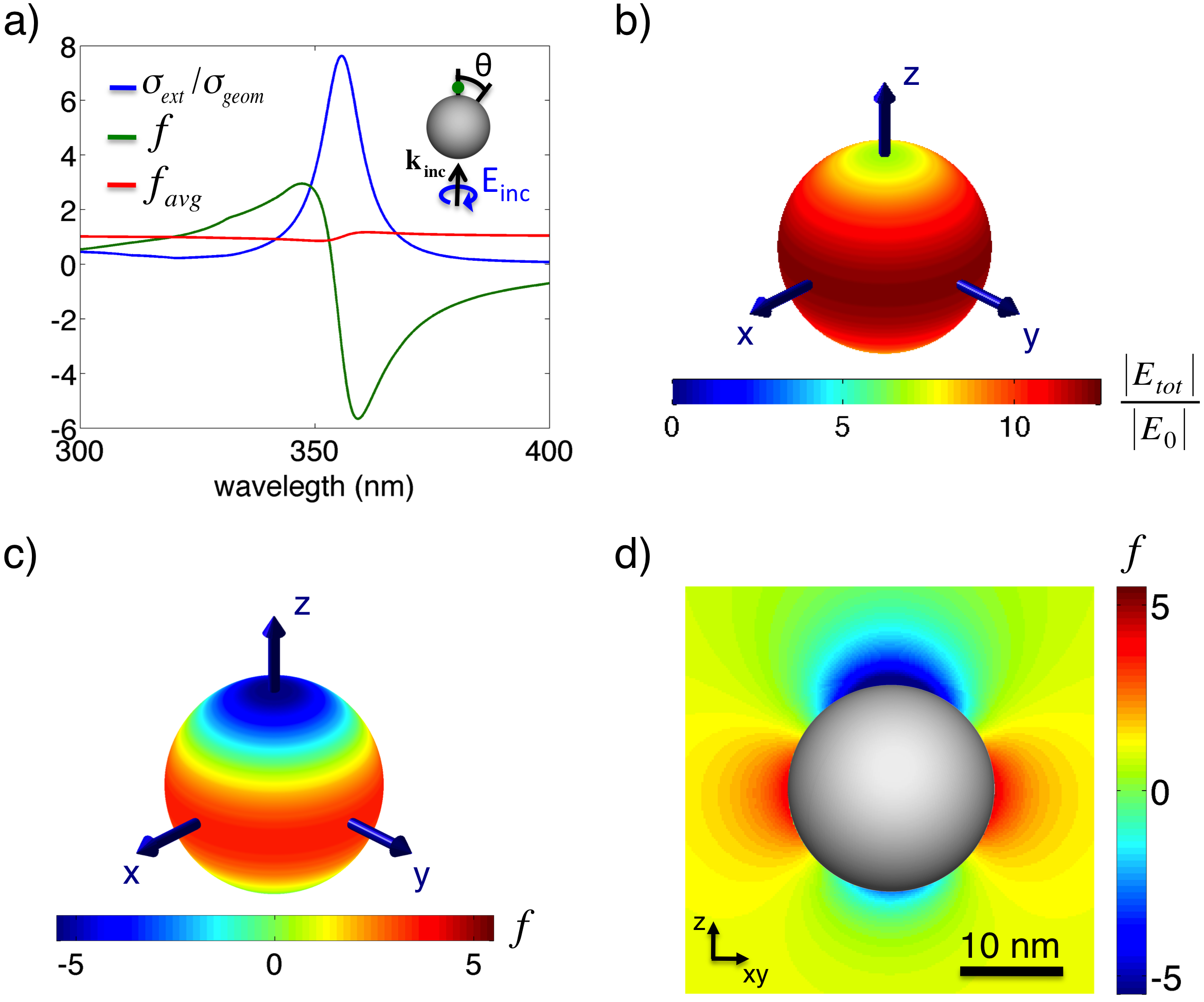
As an example, consider the response of a nm radius silver sphere, determined by rigorously solving Maxwell’s equations using the Boundary Element Method (BEM) deAbajoandHowie (2002, 1998). Fig.1a plots the extinction cross section of the sphere, as well as the position-dependent CD enhancement factor, , calculated at a point nm above the particle, and the average enhancement, defined as the local enhancement integrated over a surface, normalized to the surface area: . As seen, the localized surface plasmon resonance occurs at a wavelength of nm, where the extinction cross-section is maximum. Here, the absolute value of the density of chirality is minimized. Since the electric dipole is on-resonance, the phase of will be delayed with respect to the incoming magnetic field. Therefore, the phase of the total (incident and scattered) fields results in and, consequently, according to Eq.2, .
Slightly off the plasmonic resonance, however, the ideal phase relation between the electric and magnetic field is not completely destroyed, and a local enhancement of can be obtained. Fig.1b and c show the total electric field enhancement and the CD enhancement factor , plotted along a spherical surface nm away from the particle for nm, red-shifted slightly from the plasmon resonance of nm. As seen, is both positively and negatively enhanced in different regions around the nanoparticle. Here, a negative enhancement of indicates that a left-handed excitation will induce right-handed near fields. Positive enhanced values of imply that the chirality will be increased while the handedness of the fields will remain unchanged.
Neglecting retardation of the incident electromagnetic fields in the vicinity of the particle, the analytic average density of CD enhancement is found to be . Fig.1a (red line) plots this averaged CD enhancement factor for the fully electrodynamically calculated fields around the particle. The small deviations from the predicted analytical value of are due to retardation effects.Therefore, a plasmonic nanoparticle illuminated by circularly polarized light will not enhance CD spectroscopy if isotropically surrounded by chiral molecules. However, surface-enhanced CD spectroscopy could be achieved by creating a surface of closely-packed nanoparticles, where molecules are prohibited from laying in regions of opposite . The specifics of the design of such a surface will be left for future work.
Now consider an ideal optical-frequency magnetic dipole illuminated by CPL. Expressions for the CD enhancement factor are included in Table 1 as . As with electric dipoles, local enhancement of is possible, but averaging the CD enhancement factor on a sphere of constant radius yields no net enhancement.
This situation is significantly modified when considering a combination of an isotropic electric and an isotropic magnetic dipole. If the dipoles are located at the same spatial position, symmetry dictates that they will not interact; accordingly bi-anisotropy will not be generated sheikoleslami:2011. In the electrostatic limit, assuming that the magnetic fields produced by an electric dipole as well as the electric fields produced by a magnetic dipole are negligible, the total near fields produced by such a system can be approximated as:
| (7) |
| (8) |
For circularly polarized incident light, averaging the position dependent ( in Table 1) gives the following expression:
| (9) |
which in general can be greater than . and account for the phase of the magnetic and electric polarizability respectively.
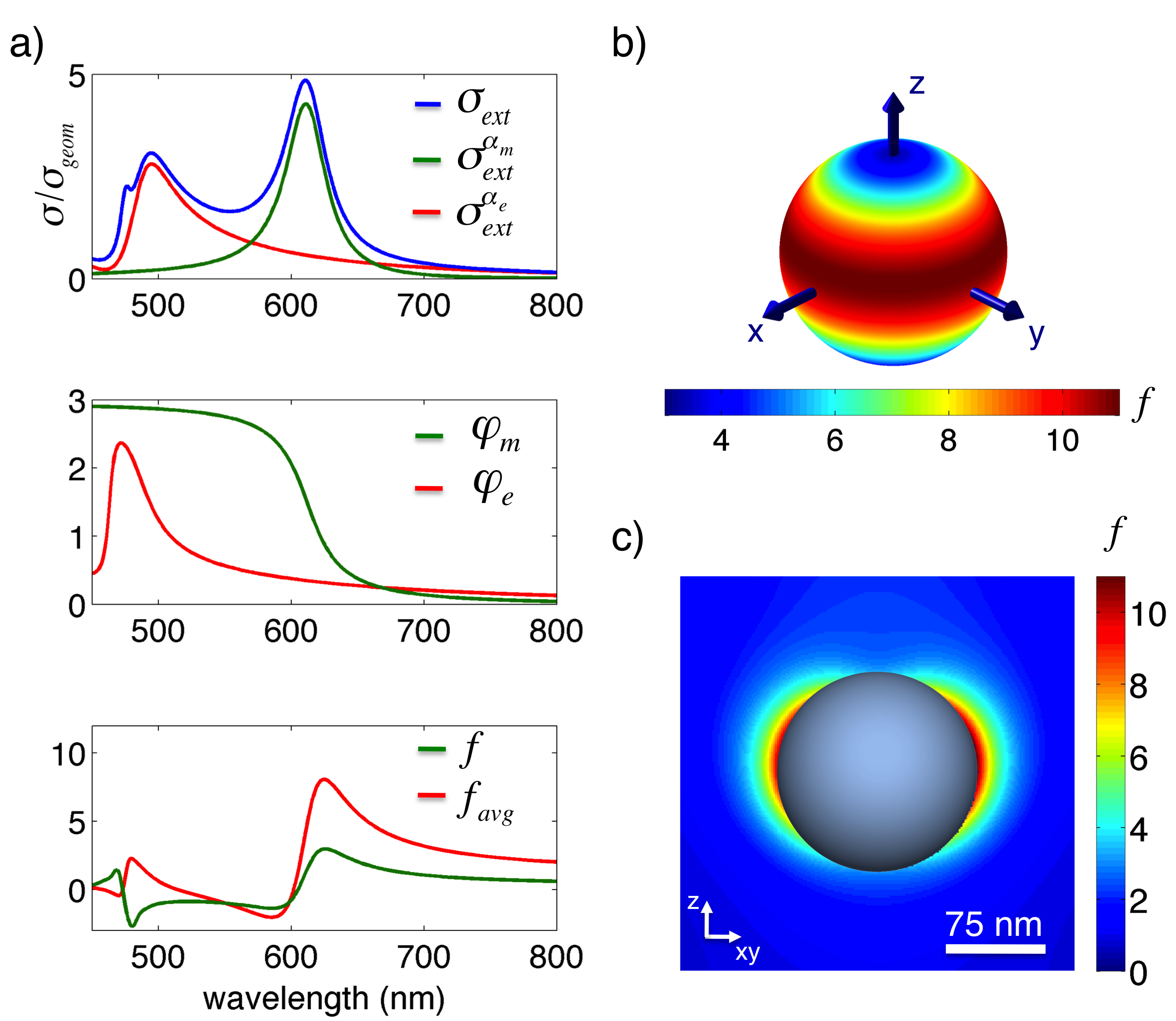
While optical-frequency magnetic dipoles are uncommon in nature, recently-engineered nanostructures can exhibit strong electric and magnetic resonances at visible and near-infrared frequencies. Examples include split-ring resonators, nanocups or nanocrescents Zhang:2011bo; Shevchenko:2009, as well as rings of metallic nanoparticles Manoharan:2010us. As an example of a system showing isotropic electric and magnetic resonances, we consider a spherical silicon nanoparticle GarciaEtxarri:2011bo; Evlyukhin:2012; Kuznetsov:2012. Due to their high refractive index, these particles support electric and magnetic Mie resonances in the visible and infrared part of the spectrum GarciaEtxarri:2011bo. The upper panel of Fig.2a shows the geometrically normalized extinction cross section of a nm radius Si nanoparticle, along with the contribution of the lowest order electric () and magnetic () modes to the total extinction spectrum, calculated through Mie theory Bohren:2008wi. The middle panel illustrates the phase behavior of the polarizabilities and . According to Eq.9, the averaged chiral density will be increased only if while , a condition which is satisfied in the green and red regions of the visible spectrum. The lower panel plots the local chiral density at a point 1 nm above the nanoparticle (green) and the averaged chiral density (red) around the particle. As seen, unlike an isolated electric or magnetic dipole, the total averaged chiral density is enhanced compared to CPL.
Fig.2b and c plot the three-dimensional surface ( nm above the sphere) and two-dimensional cross-section of for nm. At this wavelength, the maximum local and averaged CD enhancement factor occur. Remarkably, is exclusively positive throughout all space at this wavelength. Moreover, the averaged enhancement factor exceeds that of circularly polarized light by nearly an order of magnitude. In other words, solution-based CD spectroscopy can be enhanced globally via isotropic achiral nanostructures supporting electric and magnetic dipoles.
In conclusion, we have shown how individual electric or magnetic dipoles can tailor the local density of chirality and thus the circular dichroism enhancement. Individual electric or magnetic dipoles can only locally (but not globally) increase CD enhancement factor. Consequently, they could be used to increase the sensitivity of surface-based circular dichroism techniques, but are ill-suited for solution-phase measurements. In contrast, combinations of electric and magnetic dipoles can achieve both local and net, global enhancements of the CD signal, and are therefore strong candidates for solution-phase surface enhanced (V)CD. Si nanoparticles, for example, increase the averaged CD enhancement factor by nearly a factor of ten. Further engineering of the electric and magnetic response of nanoantennas may lead to much higher enhancement factors. Interestingly, we demonstrate that structurally chiral particles are not necessary to enhance CD spectroscopy. These results set the theoretical basis for field-enhanced chiral spectroscopic techniques, providing a new twist to molecular probes in fields ranging from molecular biology to pharmacology.
Acknowledgements.
We thank Sassan Sheikholeslami and Hadiseh Alaeian for insightful discussions and the Donostia International Physics Center (DIPC) for their computational resources. Funding from a NSF Career Award (DMR-1151231) and Stanford’s Global Climate and Energy Project are gratefully acknowledged.References
- Ueshima and Asami (2003) R. Ueshima and T. Asami, Nature 425, 679 (2003).
- Hegstrom and Kondepudi (1990) R. A. Hegstrom and D. K. Kondepudi, Scientific American 262, 108 (1990).
- Barron (2004) L. D. Barron, Molecular Light Scattering and Optical Activity, 2nd ed. (Cambridge University Press, 2004).
- Rodger (2006) A. Rodger, Circular Dichroism and Linear Dichroism. Enciclopedia of Analytical Chemistry (2006).
- Polavarapu and Zhao (2000) P. L. Polavarapu and C. Zhao, Fresenius’ Journal of Analytical Chemistry 366, 727 (2000).
- Nie and Emory (1997) S. Nie and S. R. Emory, Science 275, 1102 (1997).
- Kneipp et al. (1997) K. Kneipp, Y. Wang, H. Kneipp, L. Perelman, I. Itzkan, R. Dasari, and M. Feld, PRL 78, 1667 (1997).
- Xu et al. (1999) H. Xu, E. J. Bjerneld, M. Käll, and L. Börjesson, Physical Review Letters 83, 4357 (1999).
- Neubrech et al. (2008) F. Neubrech, A. Pucci, T. Cornelius, S. Karim, A. Garcia-Etxarri, and J. Aizpurua, Physical Review Letters 101, 157403 (2008).
- Tang and Cohen (2010) Y. Tang and A. E. Cohen, Physical Review Letters 104, 163901 (2010).
- Tang and Cohen (2011) Y. Tang and A. E. Cohen, Science 332, 333 (2011).
- Bliokh and Nori (2011) K. Y. Bliokh and F. Nori, Physical Review A 83, 021803 (2011).
- Andrews and Coles (2012) D. L. D. Andrews and M. M. M. Coles, Optics Letters 37, 3009 (2012).
- Hendry et al. (2012) E. Hendry, R. Mikhaylovskiy, L. Barron, M. Kadodwala, and T. J. Davis, Nano Letters 12, 3640 (2012).
- Plum et al. (2009) E. Plum, V. A. Fedotov, and N. I. Zheludev, Journal of Optics A: Pure and Applied Optics 11, 074009 (2009).
- Hendry et al. (2010) E. Hendry, T. Carpy, J. Johnston, M. Popland, R. V. Mikhaylovskiy, A. J. Lapthorn, S. M. Kelly, L. D. Barron, N. Gadegaard, and M. Kadodwala, Nature Nanotechnology 5, 783 (2010).
- Klimov et al. (2012) V. V. Klimov, D. V. Guzatov, and M. Ducloy, Europhysics Letters 97, 47004 (2012).
- Guzatov and Klimov (2012) D. Guzatov and V. Klimov, arXiv:1203.5393v1 (2012).
- Schäferling et al. (2012) M. Schäferling, D. Dregely, M. Hentschel, and H. Giessen, Physical Review X 2, 031010 (2012).
- Slocik et al. (2011) J. M. Slocik, A. O. Govorov, and R. R. Naik, Nano Letters 11, 701 (2011).
- Zhang and Govorov (2012) H. Zhang and A. O. Govorov, arXiv:1207.0150v1 (2012).
- Govorov et al. (2010) A. O. Govorov, Z. Fan, P. Hernandez, J. M. Slocik, and R. R. Naik, Nano Letters 10, 1374 (2010).
- Govorov (2011) A. O. Govorov, The Journal of Physical Chemistry C 115, 7914 (2011).
- Govorov and Fan (2012) A. O. Govorov and Z. Fan, ChemPhysChem 13, 2551 (2012).
- Lieberman et al. (2008) I. Lieberman, G. Shemer, G. Markovich, and 5, Angewandte Chemie (International Edition) 47, 4855 (2008).
- G_ep=14πeikrk2r3(3n(n⋅ p) p)pr=—r-r_0—r_0rn—r-r_0—