Further author information: (Send correspondence to C. Del Vecchio)
C. Del Vecchio: E-mail: cdelvecchio@arcetri.astro.it, Telephone: +39 055 2752261
G. Agapito: E-mail: agapito@arcetri.astro.it, Telephone: +39 055 2752315
C. Arcidiacono: E-mail: carmelo@arcetri.astro.it, Telephone: +39 055 2752293
L. Carbonaro: E-mail: carbo@arcetri.astro.it, Telephone: +39 055 2752314
F. Marignetti: E-mail: marignetti@unicas.it, Telephone: +39 0776 2993716
E. De Santis: E-mail: depotenzo@gmail.com, Telephone: +39 0776 2994705
V. Biliotti: E-mail: biliotti@arcetri.astro.it, Telephone: +39 055 2752295
A. Riccardi: E-mail: ariccardi@arcetri.astro.it, Telephone: +39 055 2752207
The Actuator Design and the Experimental Tests of a New Technology Large Deformable Mirror for Visible Wavelengths Adaptive Optics
Abstract
Recently, Adaptive Secondary Mirrors showed excellent on-sky results in the Near Infrared wavelengths. They currently provide 30mm inter-actuator spacing and about 1 kHz bandwidth. Pushing these devices to be operated at visible wavelengths is a challenging task. Compared to the current systems, working in the infrared, the more demanding requirements are the higher spatial resolution and the greater correction bandwidth. In fact, the turbulence scale is shorter and the parameter variation is faster. Typically, the former is not larger than 25 mm (projected on the secondary mirror) and the latter is 2 kHz, therefore the actuator has to be more slender and faster than the current ones. With a soft magnetic composite core, a dual-stator and a single-mover, VRALA, the actuator discussed in this paper, attains unprecedented performances with a negligible thermal impact. Pre-shaping the current required to deliver a given stroke greatly simplifies the control system, whose output supplies the current generator. As the inductance depends on the mover position, the electronics of this generator, provided with an inductance measure circuit, works also as a displacement sensor, supplying the control system with an accurate feed-back signal. A preliminary prototype, built according to the several FEA thermo-magnetic analyses, has undergone some preliminary laboratory tests. The results of these checks, matching the design results in terms of power and force, show that the the magnetic design addresses the severe specifications.
keywords:
ELT, Adaptive, Optics, Electromagnetism, Actuator, FEA1 THE SCIENTIFIC AND TECHNOLOGICAL RATIONALE
The Extremely Large Telescopes (ELT) phase A studies[1, 2, 3] are disclosing the design of future state-of-the-art ground based optical and NIR astronomical facilities. The role of current 8-10 meter class telescope will be revised in order to matches new science and new ELT discoveries. A way to obtain possible and qualified synergies is to work at similar spatial resolution. Given the telescopes resolutions and the extensive use of Adaptive Optics (AO) techniques on both classes, we propose to consider AO at visible wavelengths for 8 meter telescopes in order to obtain similar wavelength on diameter ratios. The AO@SW (Adaptive Optics at Short Wavelengths) proposal investigates this possibility through numerical simulations[4].
One of the main science drivers for ELTs is the star formation histories of galaxies through stellar population studies[5]. In particular, resolved stellar population analysis in regions not accessible today because of extreme crowding (because of the spatial resolution limit of the instruments) will allow to analyze the formation histories of our portion of the universe up to Virgo or (hopefully) Coma galaxies clusters[6]. A further, interesting science drive is the study the populations of our and close by galaxies of single age stars ensembles such as Globular and Open Cluster looking at magnitude fainter than turn-off point.
It is well known that large observed wavelengths boosts the sensitivity of the color magnitude diagram (CMD) to the age and to the metallicity of the star clusters. At ELT spatial resolutions this corresponds to NIR CMD such K vs J-K: however at the same high spatial resolution an 8 meter class telescope may provide the photometry measurements of the same stars detected by the ELT but at the V or R band offering a much larger baseline for the CMD.
2 INTRODUCTION
The current Adaptive Secondary Mirrors (ASM), with a inter-actuator spacing and a bandwidth, showed recently excellent on-sky results at NIR wavelengths. Operating an ASM at visible wavelengths is a challenging task: the more demanding requirements are the higher spatial resolution and the greater correction bandwidth. In fact, the turbulence scale is shorter and the parameter variation is faster. Typically, the former is not larger than (projected on the secondary mirror) and the latter is . As a consequence, the actuator for a visible wavelength AO system has to be more slender and faster than the current ones. The actuators developed for AO at NIR wavelengths of the 8 meter class telescopes, described in [7], are not suitable for shorter wavelengths — where a low-order and long-stroke ASM is required. Therefore, different designs, such as the ones described in [8, 9], have been exploited, among the large variety of linear motors developed in the past years[10, 11, 12]. Focusing the magnetic flux density by means of suitable statoric yokes-like components of soft iron material allowed to decrease by one order of magnitude the power dissipated to actuate the correction force. Nevertheless, those very good performances were obtained with a significant mechanical complexity.
With a soft magnetic composite core consisting of a dual-stator and a single-mover, VRALA[13, 14] (Variable Reluctance Adaptive mirror Linear Actuator), the actuator discussed in this paper, attains unprecedented performances with a negligible thermal impact. With a simpler geometry an even better performances, it is the ideal candidate for the AO actuators at visible wavelengths. Pre-shaping the current required to deliver a given stroke greatly simplifies the control system, whose output supplies the current generator. As the inductance depends on the mover position, the electronics of this generator, provided with an inductance measure circuit, works also as a displacement sensor, providing the control system with an accurate feed-back signal. The entire design process is based on numerical simulations: the Finite Element Analysis (FEA) method is applied for the electromagnetic, mechanical and thermal studies, a CAD electronics design and simulation system defines the electronic hardware architecture, and the control system is developed by means of the Matlab/Simulink® software. A preliminary prototype, built according to this simple, effective and low power consumption design, is aimed for checking the study results — and possibly correct/revise any critical issue.
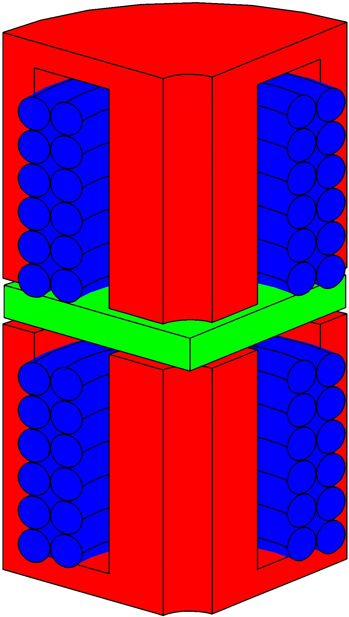
Recalling the description given in [13, 14], the basic static component of VRALA is a cylindrical, hollow shaped soft iron stators, that accommodate the coils. The flux lines of the magnetic field produced by the current flowing in the coil are conveyed into a mover, a disk also built of soft iron and facing the stator, through an air gap. As the magnetic pressure in that gap works as a pull-only force on the mover, a second stator, placed symmetrically with respect to the mover, is needed to produce the pushing force. The force is applied to the ASM by a shaft fixed to the mover, mounted in the stator central hole parallelly to its axis by means of two membranes. As the current/force transfer function is highly non-linear — the mover position and the magnetic characteristics avoid to analytically identify such a function — the control system design is based on an open-loop preshaper current function, determined via a look-up table obtained computing the magnetostatics of the system for many currents and positions, and on a very simple, proportional-only closed loop which takes care of the (very small) residual corrections. The current command signal generated by the control system feeds a power supplier, whose electronics is designed to deliver the needed current and to measure the device inductance, which depends on the mover position, at the same time. Providing the control system with an accurate feed-back signal, the electronics of the power supplier works also as a displacement sensor. The simpleness and efficiency of the electronic design, which adopts the more recent devices developed for power management applications, such as switching power suppliers, allows to minimize the thermal impact in the delicate optical environment.
3 The Design
Comsol Multiphysics®, the code adopted for the numerical analyses[15], allows to easily generate a FEM mesh both accurate and numerically smooth, so that exploring the effect of the material choices and the geometry variations on the solutions is quite fast and accurate. A single Matlab script can accomplish in a single process such a geometrical task, the geometry mesh, the embedding of the mesh elements in the electromagnetic “azimuthal currents” module, taking into account the physical properties of the chosen materials, including the air, the non linear solution of the non linear system for the magnetic potential variable, and the post-processing computation of the magnetic force. This process is the same described in [13], with two relevant differences. First, the multi-turn capability in Comsol allows to apply the coil a current excitation and to avoid meshing the actual coil. Second, because of the very high current time derivatives to be applied by the control system, described in Sec. 3.3.1, that induces high eddy currents in both the stators and the mover, these components have been built with Somaloy. The model geometry is sketched in Fig. 3; the specifications are summarized in Tab. 3.
| rms force (turbulence correction) | |
|---|---|
| max force (static) | |
| max force (dynamic) | |
| stroke (usable) | |
| stroke (mechanical) | |
| bandwidth | |
| typical inter-actuator spacing | |
| typical actuator length | |
| typical mover mass |
3.1 MAGNETOSTATICS: COMPUTING THE FORCE
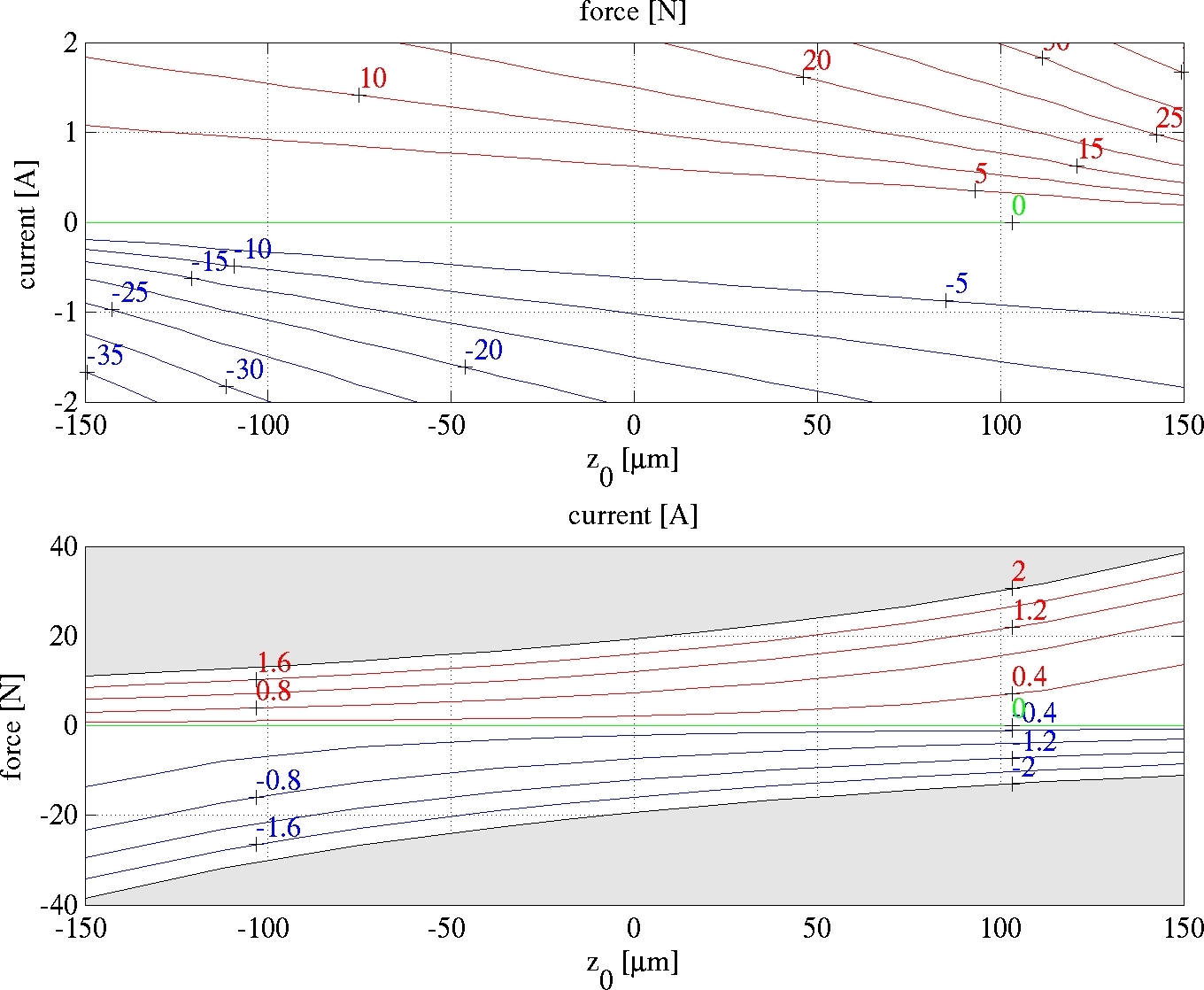
The magnetostatic computations are aimed to define the optimized geometry, by means of the process discussed in [15], as well as to determine the relationship between the force , the mover position and the coil current , needed by the control system, discussed in Sec. 3.3.1. The geometry giving the maximum efficiency, namely , is summarized in Tab. 2; the values of the above mentioned function are given in Fig. 2, where both and its inverse function , the one actually needed by the control system, are plotted.
| outer radius of stator | height of coil slot | ||
|---|---|---|---|
| inner radius of stator | width of coil slot | ||
| height of stator | gap height | ||
| height of stator slot | wire outer radius | ||
| outer radius of mover | insulation thickness | ||
| inner radius of mover | coil resistance | ||
| height of mover | number of turns | ||
| mean radius of coil slot | filling factor |
3.2 FREQUENCY-DOMAIN: MEASURING THE DISPLACEMENT
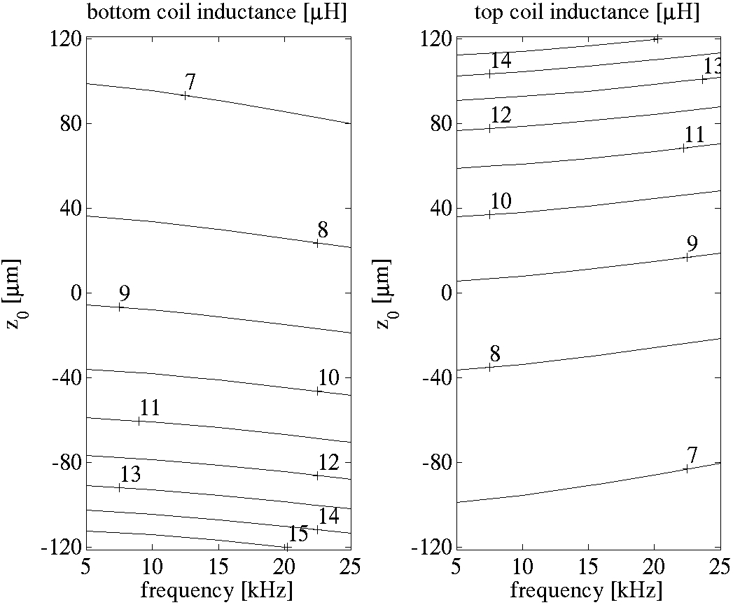
Feeding the coils with sinusoidal currents and running the solution in the frequency domain at several positions of the mover allows to compute the top and bottom inductances as a function of the current frequency. Provided that the current values are small enough, to avoid an extra power dissipation, and they are phased, to have a null resulting force on the mover, such a run allows to compute the top and bottom inductances as a function of . The results, summarized in Fig. 3, show that the inductance-position relationship is robust from the control system standpoint at all the considered frequencies: over the range the inductance typically changes by a factor of 2.5.
3.3 TIME-DOMAIN: THE CLOSED LOOP
Naming the mover mass, the typical payload due to the ASM, the force applied to the mover, whose position is , is the viscous damping coefficient and is the bending stiffness constant of the portion of ASM which applies the elastic force to the actuator shaft, the dynamics of the system is governed by Eq. 1
| (1) |
where and are the the damping ratio and the natural frequency of the system, respectively. Adding to the to the FEM described in Sec. 3 the ALE (Arbitrary Lagrangian-Eulerian method[15]) application mode, which implements a deformable mesh, the Ordinary Differential Equation (ODE) defined by Eq. 1 allows to describe the dynamics of the mover.
3.3.1 The control system
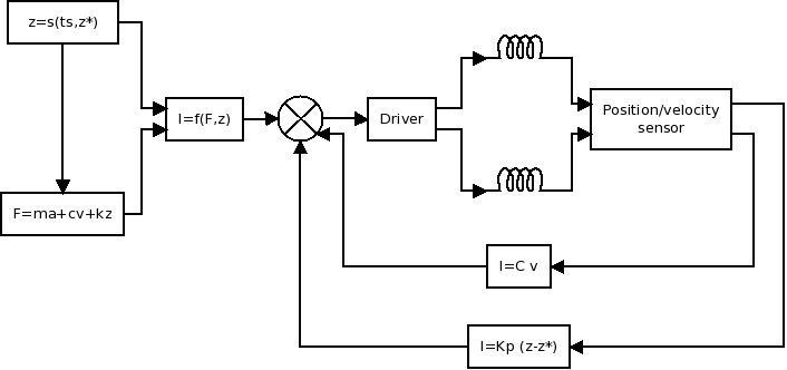
The control system, schematized in Fig. 4, is based on a preshaper and a Proportional-Velocity control. Although the magnetic force is strongly non linear both in terms of position and current , so that a classic linear controller could not work properly, the reference signal, the set point , is always a step of variable amplitude. Therefore, we can easily apply an open loop current and desired position signals that drive the actuator to without exciting . In fact, the 2-order system of Eq. 1 may be critically damped simply choosing the value of (the electronic damping) that makes . Defining the desired settling time, replacing the discontinuous unit step function defined in Eq. 4 with the smoothed Heaviside step function defined in Eq. 8, where is a polynomial that makes continuous up to its fourth time derivative, the force is computed by means of the Eq. 1 and the current is computed with , defined in Sec. 3.1. As the actuator may follow with some error the position curve, a proportional control adjusts the current curve with a correction proportional to the error via the constant .
| (4) |
| (8) |
3.3.2 The electronics
The pre-shaping defined in Sec. 3.3.1 dramatically simplifies the hardware of the control system, whose output supplies the current generator. As the inductance depends on the mover position, the electronics of the current generator, provided with an inductance measure circuit, works also as a displacement sensor, supplying the control system with the feed-back values and with the needed precision. This capability is provided by two sniffers, one for each coil (included in the “Position/velocity sensor” block in Fig. 4), synchronized with the driver (which embodies the current generator) via a control logic. Equipped with a processor that acquires the coil voltage, the sniffers perform some computational tasks in order to infer the error displacement , as well as, by a time derivation, the velocity . The driver is a switching-like device, which controls both the coils. This simple, effective and low-consumption electronic design, which adopts the more recent devices developed for power management applications, such as switching power suppliers, greatly contributes to reduce the thermal impact.
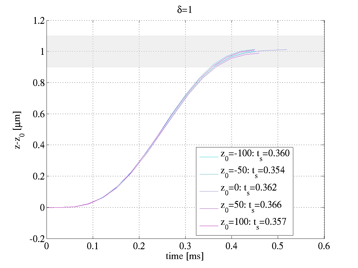
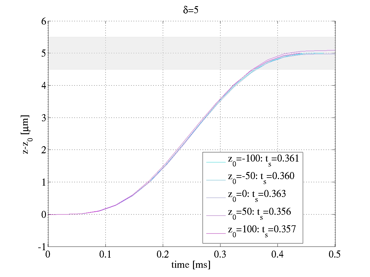
3.4 The step response
In order to test the performances of the control system, we have selected and , a value corresponding to the rigidity of a tick Zerodur ASM whose actuators are separated by , in Eq. 1 and , , and in Fig. 4. Commanding , where is the requested stroke, for ranging from from to , gives very good time responses: the settling time ranges from , largely below the specification in terms of bandwidth. Fig. 5 shows the step response for the lower and upper limits of the considered values.
 |
 |
4 EXPERIMENTAL VALIDATION
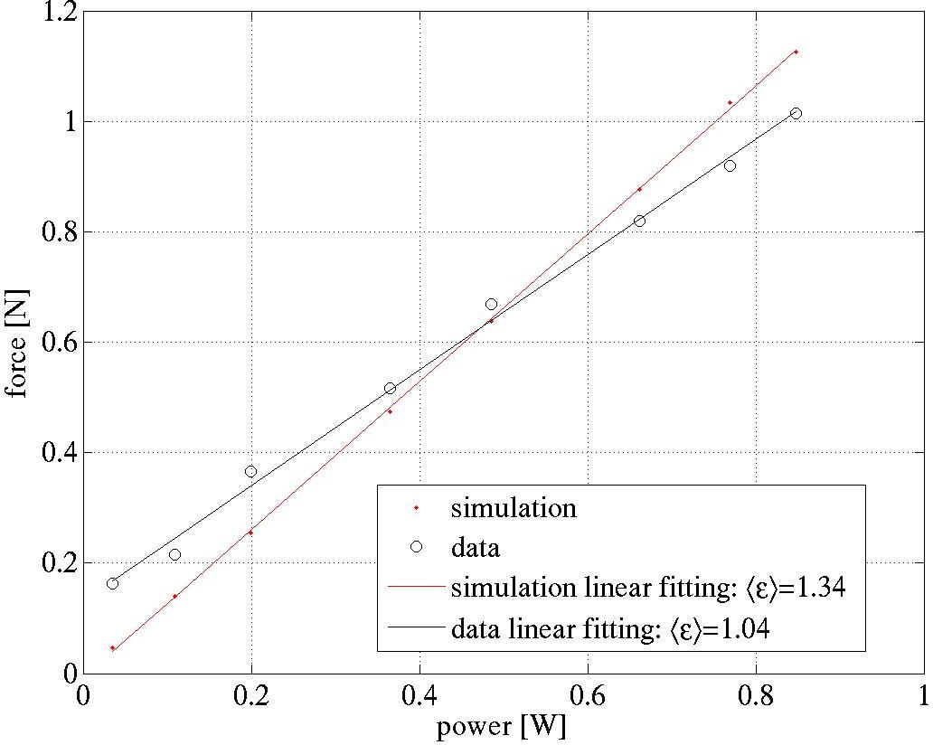
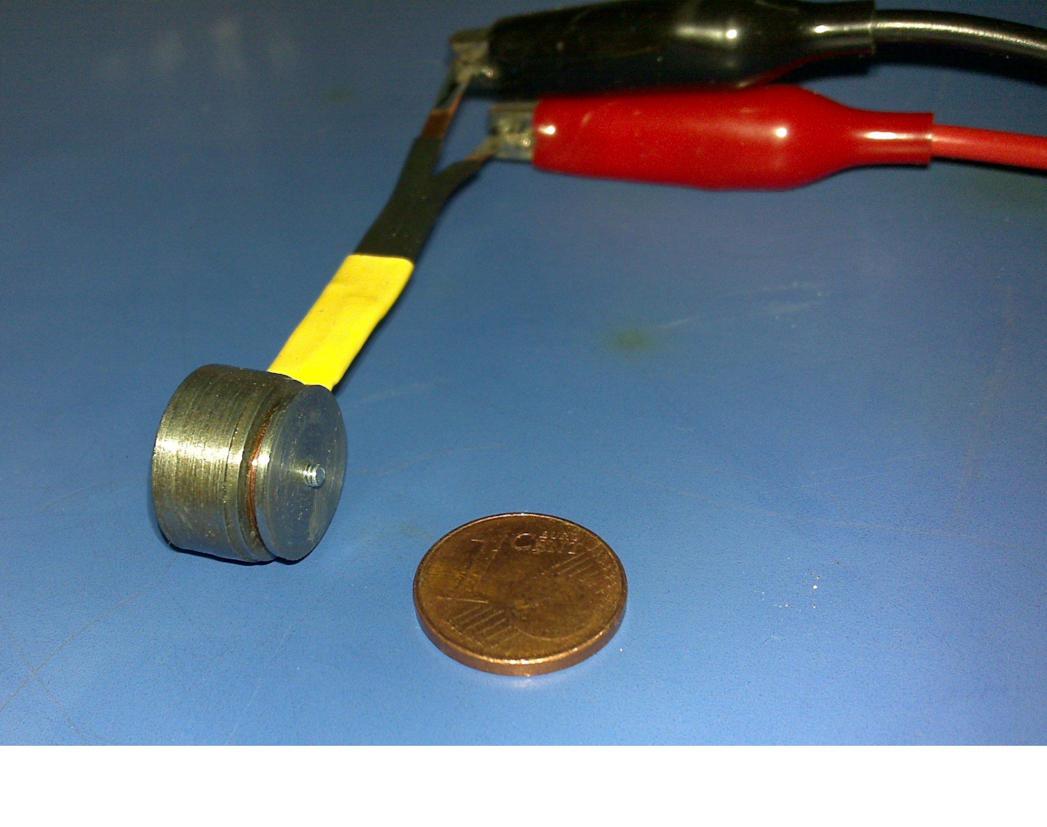
A preliminary, magnetostatic only test has been run in order to verify the reliability of the FEA model. Instead of building an expensive and delicate complete actuator with a Somaloy core, a simpler single stator/mover unit, shown in Fig. 6, made of the cheaper C40 soft iron, have been manufactured in the laboratory. The nominal air gap has been replaced by a tick plastic spacer. The results of the magnetostatic solution of the FEM model of such a prototype, taking as B-H curve some data measured on a sample of the C40, are shown in Fig. 6, along with the experimental data. The difference between the values computed by the simulation and the measured ones ranges from to in the current span — corresponding to . We note that the efficiency, also reported in Fig. 6, is reduced by a factor of four with respect to the full model described in the previous sections, mainly because of the increasing of the gap. Considering that the available C40 data were pretty rough and the manufacturing of the prototype was not as accurate as the specifications require, the numerical model is magneto-statically sound.
5 CONCLUSIONS AND FUTURE WORK
Based on a simple and very effective magnetic circuit and on a highly performing control system, VRALA allows to implement the AO technology at visible wavelengths, where large forces and unprecedented actuator densities are required.
The FEA multiphysics simulation results demonstrate that this actuator exhibits very low power dissipations and applies the corrections with an excellent bandwidth, thanks to the hardware and the software designs of the control system. With an efficiency of and an overall radius that allows actuator separations up to , VRALA can provide strokes up to in less than — largely below the bandwidth goal of — with an extremely low thermal impact. The compact, effective and simple control system exhibits the capability of driving the actuator while sensing its motion without any additional feed-back component.
The force measures carried out on the preliminary prototype, although built with a rough, off-the-shelf available material, show that the magnetostatic computations are correct.
These promising results indicate the future developments, in terms of simulation and laboratory activities.
Further, more complex numerical simulations are needed: complete 2D and a 3D FEA models must be developed in order to simulate the complex response of the system, in terms of mechanical and thermal deformations, possible electromagnetic variations caused by tolerances and mutual effect by close actuators, as well as the fluid dynamics governing the convective heat exchanges.
A full Somaloy prototype is planned, in order to verify the response of the material selected to build the iron core. Because of the efficiency is proportional to the filling factor, replacing the conventional solenoid with a pre-wounded copper strip is also planned, in order to increase, according to some preliminary computations, the filling factor up to . The electronics of the control system, currently under construction, will allow to test the real dynamics of the actuator when operating in turbulence corrections. Finally, the construction of 4-by-4 actuators demonstrator will provide some important data on the actual opto-mechanical response of the full system and the multi-channel control electronics, currently in the feasibility phase.
Acknowledgements.
This study was supported by the TECNO INAF 2009 grant from the Italian Istituto Nazionale di Astrofisica (INAF). The authors would like to thank Riccardo Crosa and Federico Della Ricca from Höganäs Italy, for insight and guidance through the Somaloy materials.References
- [1] Nelson, J. and Sanders, G. H., “The status of the thirty meter telescope project,” in [Advanced Optical and Mechanical Technologies in Telescopes and Instrumentation ], Stepp, L. M. and Gilmozzi, R., eds., Proc. SPIE 7012, E.1–E.11, SPIE (6 2008).
- [2] Johns, M., “The Giant Magellan Telescope (GMT),” in [Advanced Optical and Mechanical Technologies in Telescopes and Instrumentation ], Andersen, T., ed., Proc. SPIE 6986, E.1–E.11, SPIE (6 2008).
- [3] Gilmozzi, R. and Spyromilio, J., “The European Extremely Large Telescope (E-ELT),” The Messenger 127, 11–19 (2007).
- [4] Agapito, G., Arcidiacono, C., Quiros-Pacheco, F., Puglisi, A., and Esposito, S., “Infinite impulse response modal filtering in visible adaptive optics,” in [Adaptive Optics Systems III ], Ellerbroek, B. L., Marchetti, E., and Véran, J.-P., eds., Proc. SPIE 8447, SPIE (7 2012).
- [5] Hook, I., “The science case for the European ELT,” in [Science with the VLT in the ELT Era ], Moorwood, A., ed., Astrophysics and Space Science Proceedings, 225–232, Springer Netherlands (2009). 10.1007/978-1-4020-9190-2_38.
- [6] Deep, A., Fiorentino, G., Tolstoy, E., Diolaiti, E., Bellazzini, M., Ciliegi, P., Davies, R. I., and Conan, J.-M., “An E-ELT case study: colour-magnitude diagrams of an old galaxy in the Virgo cluster,” "Astronomy and Astrophysics" 531, A151 (July 2011).
- [7] Del Vecchio, C., Gallieni, D., Martin, H. M., Riccardi, A., Brusa, G., and Biasi, R., “Design improvements of the LBT adaptive secondary,” in [Beyond Conventional Adaptive Optics ], Vernet, E., Ragazzoni, R., Esposito, S., and Hubin, N., eds., Proc. ESO 58, 435–441, ESO (5 2001).
- [8] Del Vecchio, C., Marignetti, F., Riccardi, A., Scarano, M., and Cancelliere, P., “Selecting the electromagnetic actuator of the ELT primary mirror,” in [Advances in Adaptive Optics II ], Ellerbroek, B. L. and Bonaccini Calia, D., eds., Proc. SPIE 6272, 157–167, SPIE (5 2006).
- [9] Del Vecchio, C., Biasi, R., Gallieni, D., Riccardi, A., and Spairani, R., “Actuating the deformable mirror: a multiphysics design approach,” in [Advanced Optical and Mechanical Technologies in Telescopes and Instrumentation ], Atad-Ettedgui, E. and Lemke, D., eds., Proc. SPIE 7018, E.1–E.11, SPIE (6 2008).
- [10] Vese, I.-C., Marignetti, F., and Radulescu, M., “Multiphysics approach to numerical modelling of a permanent-magnet tubular linear motor,” Transactions on Industrial Electronics, IEEE 57, 320–326 (Jan. 2010).
- [11] Marignetti, F., Del Vecchio, C., Riccardi, A., and Scarano, M., “Optimization of single-phase linear tubular pm actuators for ground and space-based telescope applications,” Electrical Engineering Research Report 1, 1–8 (Mar. 2009).
- [12] Marignetti, F., “On liquid-nitrogen-cooled copper-wound machines with soft magnetic composite core,” Transactions on Industrial Electronics, IEEE 46, 984–992 (May 2010).
- [13] Del Vecchio, C., Marignetti, F., Agapito, G., Tomassi, G., and Riccardi, A., “Vrala: Designing and prototyping a novel, high-efficiency actuator for large adaptive mirrors,” in [Adaptive Optics Systems ], Ellerbroek, B. L., Hart, M., Hubin, N., and Wizinowich, P. L., eds., Proc. SPIE 7036, SPIE (6 2010).
- [14] Del Vecchio, C., Agapito, G., Tomassi, G., and de Santis, E., “Modeling VRALA, the next-generation actuator for high-density, tick secondary mirrors for astronomy,” in [Comsol Conference ], Proc. Comsol, Comsol (11 2010).
- [15] COMSOL AB., Comsol Multiphysics (11 2011). Version 4.2a.