Geometry-induced phase transition in fluids: capillary prewetting.
Abstract
We report a new first-order phase transition preceding capillary condensation and corresponding to the discontinuous formation of a curved liquid meniscus. Using a mean-field microscopic approach based on the density functional theory we compute the complete phase diagram of a prototypical two-dimensional system exhibiting capillary condensation, namely that of a fluid with long-ranged dispersion intermolecular forces which is spatially confined by a substrate forming a semi-infinite rectangular pore exerting long-ranged dispersion forces on the fluid. In the – plane the phase line of the new transition is tangential to the capillary condensation line at the capillary wetting temperature, . The surface phase behavior of the system maps to planar wetting with the phase line of the new transition, termed capillary prewetting, mapping to the planar prewetting line. If capillary condensation is approached isothermally with , the meniscus forms at the capping wall and unbinds continuously, making capillary condensation a second-order phenomenon. We compute the corresponding critical exponent for the divergence of adsorption.
pacs:
68.08.Bc, 05.20.Jj, 68.18.Jk, 71.15MbCapillary wetting is crucial in a wide variety of natural processes and technological applications. From the wetting properties of plant leaves GouLiuPlantSci07 to building of nanoreactors Dum09 and design of “lab-on-chip” devices BerardinoDietrich2012AndSquires05 . It also provides one of the most striking manifestations of the attractive intermolecular forces governing the behavior of matter. For microscopic systems, concepts such as surface tensions and contact angles become quite limited. One must account for the molecular structure of the fluid, since most non-trivial effects in confinement are caused by the interplay of different length scales corresponding to particle sizes, ranges of intermolecular potentials and dimensions of confinement. These parameters act as independent thermodynamic fields, leading, according to the Gibbs rule, to a rich surface phase behavior and metastability caused by the interplay of different wetting mechanisms Evans90 ; HendersonBook92 . The main theoretical approaches to confined fluids are mean field Van der Waals loops, renormalization group theory, and effective Hamiltonians. While the latter two have been successfully applied to establishing the universality of some surface critical phenomena, e.g. MilchevPRL03AndSartoriParryJPhysCondensMatt02 ; TasDietPRL06 , far less attention has been given to the molecular structure of an adsorbate. Here we adopt a fully microscopic approach based on density functional (DF) theory leading to a molecular model for the fluid, undertaking a systematic investigation of wetting in a semi-infinite rectangular pore. The scenario of drying by a fluid with short-ranged forces and zero contact angle has been considered within a DF approach in Ref. Roth11, , but without fully exploring the phase diagram. Here we obtain detailed information on density profiles and menisci shapes, adsorption isotherms, phase diagrams and critical behavior. Noteworthy is also that our approach is not restricted to complete wetting scenarios as in previous works, e.g., Refs. TasDietPRL06, ; DarbellayYeomans92, .
Consider a long-range interacting fluid confined to a rectangular pore of width and length by a substrate whose walls exert long-ranged dispersive forces on the fluid. The system is assumed infinite in the direction normal to the – plane, where it is also connected to a thermostat fixing the values of the chemical potential and temperature . Under these assumptions the density profile of the fluid inside the pore is two dimensional (2D): . The free energy of the pairwise interacting fluid in an external field , formed by the substrate walls, is a unique functional of the one-body density, which in the grand canonical ensemble is given by
| (1) |
An approximation for the canonical free energy functional follows from the perturbation around a hard sphere fluid in powers of the attractive potential up to the first order Evans :
| (2) |
where is the ideal free energy, is the Boltzman’s constant and – the thermal wavelength, and is the configurational part of the free energy. Using the Carnahan and Starling equation of state for the gas of hard spheres with diameter , it can be approximated as CS
| (3) |
The long-ranged fluid-fluid forces can be described following the Barker and Henderson prescription BH
| (4) |
with being the strength parameter, which we will be using as the unit of energy.
Finally, for simplicity and without loss of generality, we model the substrate by
| (5) |
() where the superscript stands for bottom, left and top walls respectively, and each
| (6) |
is the 3-9 potential of an isolated planar wall characterized by the parameters of strength , range and low- cut-off ; Yatsyshin2012 . Throughout this letter we fix the value of the capillary width and the wall parameters: , , . Presented examples differ in the values of , which will be provided along with the wetting temperatures and macroscopic contact angles at bulk coexistence for each in Eq. (5). For complete prewetting lines see Supplemental Material: “1D Wetting”.
The model for substrate potential (5) was chosen for computational convenience, as well as to present several non-symmetric examples in a straightforward way. Alternatively, considering a symmetric case, one could integrate the pairwise Lennard-Jones potential over the exterior of the capillary. However, this would not alter the forthcoming discussion, since the physics of the external field comes down to the effect of long-ranged pairwise London forces acting between the fluid and the substrate particles, and is inherent in both prescriptions. Moreover, the presence of the discussed phenomena is not restricted by a particular model of the substrate, so long as it arises from the dispersive pairwise forces.
The equilibrium configurations minimize (1) and are computed numerically using a 2D extension of the method developed in Ref. Yatsyshin2012, . The 2D scheme was verified by obtaining 1D profiles with it, as well as by checking the agreement with contact sum rules HendersonBook92 . Isotherms and phase diagrams were obtained using arc-length continuation.
The DF (Geometry-induced phase transition in fluids: capillary prewetting.) is known to capture the physics of fluids at vapor- and liquid-like densities. Using a different expression for the substrate potential (e.g., an ab initio potential Ust05Marsh96AndChiz98 ), as well as a different version of the DF (e.g., accounting for the repulsive effects of molecular packing non-locally in through an improved term in (Geometry-induced phase transition in fluids: capillary prewetting.) WhiteBear ), would only induce minor quantitative changes but not add to the understanding of the physical phenomena described here and adequately captured by (Geometry-induced phase transition in fluids: capillary prewetting.) HendersonBook92 .
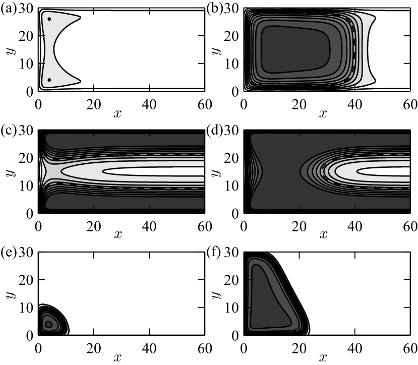
(a) and (b): , , , , , ; (c) and (d): , , , , , , , ; (e) and (f): , , , , , , , , .
As , , with being the density distribution inside a slit pore of width . The requirement to form two liquid-wall interfaces leads to the Kelvin shift of the bulk coexistence curve given (in the symmetric case ) by SaamJLowTempPhys09
| (7) |
where is the liquid-vapor surface tension, is the contact angle, and the pressures and refer to capillary-vapor and -liquid phases, which, due to (7), can coexist inside the pore. These phases transform through a discontinuous first-order transition known as capillary condensation (CC) Evans90 ; HendersonBook92 , which is essentially a shifted bulk liquid-vapor coexistence.
The phase behavior of a capped capillary is closely linked to that of the associated slit pore. For example, when CC is approached isothermally, the capped capillary can undergo a continuous second-order transition analogous to complete wetting of planar walls Parry07 . It corresponds to the gradual unbinding of the liquid meniscus from the capping wall and filling the capillary. Can the analogy with 1D wetting be extended beyond that observation?
Our computations indicate the presence of a discontinuous first-order transition corresponding to the formation of the liquid meniscus at a finite distance from the capping wall, as the fluid’s chemical potential (pressure) is increased isothermally towards CC. Depending on the “wall set”, Eqs. (5), (6), the topology of coexisting profiles can vary quite significantly, as shown in Fig. 1; also see Supplemental Material, movies 1–3. For illustration purposes, the 2D data is rescaled between capillary (white) and (black). The interface (dashed curves) is defined as and the temperature is measured in units of the bulk critical temperature .
For simplicity we focus on the symmetric case of a capped capillary formed by identical walls, Eqs. (5) and (6), with the aim of investigating its surface phase behavior, Fig. 2. Obtaining the phase diagram of the system is non-trivial and consists of several steps. First, we compute the CC line of the associated 1D slit pore, to which the system reduces as (full line, on Fig. 2(a), where is counted from the bulk liquid-vapor coexistence). Next, we compute an isotherm at a more or less arbitrary temperature below the capillary critical temperature . Figure 2(b) shows for , with the excess-over-slit grand free energy defined as . Two typical Van-der-Waals hysteresis loops reveal the presence of first-order phase transitions: a stable one at and a metastable one at (see inset on Fig. 2(b)). The stable transition corresponds to coexisting configurations of capillary vapor, Fig. 2(c), and capillary-liquid slab, Fig. 2(d). For the metastable transition the coexisting configurations are those of capillary-vapor (indistinguishable from Fig. 2(c)) and two capillary-liquid drops in the corners, Fig. 2(e). Now, applying arc-length continuation in the manner described in Yatsyshin2012 ; FrinkSalinger1 ,
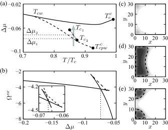
we calculate the complete phase lines of the above transitions. The results are plotted on Fig. 2(a) by a dashed line for the stable transition and a dashed-dotted line for the metastable one.
Finally, we ensure that the phase behavior of the system is fully scrutinised and there are no other transitions by calculating a set of isotherms for a broad range of temperatures and identifying the phase transitions revealed by those isotherms with the phase lines obtained above. Each isotherm spans a broad range of values of starting far from CC, where an equilibrium configuration is that of capillary-vapor (similar to Fig. 2(c)), and ending with very close to CC, where the capillary is filled. Moreover, after investigating various sets of parameters (non-symmetric capillaries, strengths and ranges of wall potentials, capillary widths, etc.), we can confirm that the phase diagram and the isotherm presented on Figs. 2(a) and 2(b) are quite typical and thus capture the essential physics of the system.
Consider first the -line (dashed line on Fig. 2(a)) forming the locus of discontinuous transitions to fluid configurations of the type shown on Fig. 2(d). It runs tangent to the CC line (full line on Fig. 2(a)) at the point and ends at . For thermodynamic routes with constant crossing the -line vertically we observe a discontinuous formation of the liquid meniscus at a finite distance to the capping wall, which unbinds to infinity as CC is approached (). Above the critical temperature the liquid meniscus at the capping wall is being formed continuously.
For values of chosen closer to from above, the meniscus forms at larger distances from the capping wall. In the limit and there is a discontinuous jump to CC: the whole capillary becomes filled with capillary-liquid.
For isothermal routes approaching at , the capped capillary remains in capillary-vapor (Fig. 2(c)), until at the CC, occurring discontinuously in the spectator phase (), drives it into capillary-liquid. The CC in that case occurs “from capillary bulk”, in contrast to the case of , when it happens “from the surfaces” of the capped capillary. This phenomenon is analogous to partial wetting in 1D, when for temperatures less than the wetting temperature of the planar wall the fluid does not adsorb an infinite liquid layer at coexistence ().
In fact, all the described phase behavior of the capped capillary is in complete analogy with the wetting phenomenology of a single planar wall immersed in vapor, when the wetting transition is first-order SaamJLowTempPhys09 . The CC line maps to the bulk coexistence line (),
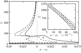
a: , , , , b: , , , , c: , , , .
and indicates the limiting values of at which the spectator fluid phase is expected to transform. Likewise, the -line maps onto the prewetting line. We therefore refer to as the capillary wetting temperature, to the phase transition at and as first-order capillary wetting, and to the transitions corresponding to -line – as capillary prewetting. Obviously, if , , the wetting temperature of the capping wall.
An interesting question arises whether, for some specific sets of substrate parameters, the transition to CC at can be continuous and not first-order. Following the observed analogy with planar wetting, such scenario should be possible and a tricritical line separating the first- and second- order CC can exist in the parameter space, even though our numerical experiments did not exhibit a second-order transition to capillary filling. By the same token, second-order capillary filling can be expected for fluids with short-ranged interactions.
Consider the dashed-dotted phase line on Fig. 2(a), , which corresponds to a discontinuous formation of capillary-liquid drops in the corners, when crossed isothermally (Fig. 2(e)). This transition is a case of corner-prefilling investigated in, e.g., Ref. RejDietNapPRE99, . In the present case its phase line is metastable, but still affects the topology of the density profiles coexisting during the capillary prewetting transition. For isothermal routes crossing at capillary prewetting takes place between a vapor phase (e.g., Fig. 2(c)) and a liquid slab phase (e.g., Fig. 2(d)). For the formation of droplets in the corners is continuous as , and the capillary prewetting transition then takes place between the configurations similar to Fig. 2(e) and Fig. 2(d).
We note that the phase-line is of lesser importance for this work, being a particular case of corner-prefilling RejDietNapPRE99 ; it is not related to CC (unlike the phase line of capillary prewetting, which defines ). For wider capillaries, whose corners are further apart, the corner prefilling transition will become stable, a triple point will exist, with the coexisting fluid configurations of types shown in Figs. 2(c)- (e).
Consider now the complete filling of the capillary as isothermally, above . Using an effective interfacial Hamiltonian model, Parry et al. Parry07 have obtained the critical exponent for the diverging length of the liquid slab. Our fully microscopic approach does not impose the existence of an interface; rather it is obtained as a consequence of the non-uniformity of the fluid caused by inter-molecular attractions. We consider the physical order parameter of the system as , the conjugate thermodynamic variable, i.e. the adsorption:
| (8) |
where integration is carried out over the entire volume of the capillary.
To properly capture the asymptote of the smooth decay of into the “capillary bulk”, which ultimately determines the critical exponent, we used a non-uniform grid, sufficiently dense in the interval to resolve the liquid-vapor interface, while imposing the boundary condition of contact with the slit pore at . The calculations were carried out for a range of temperatures, wall potentials and capillary sizes without truncating the tails of potentials (4) and (5). Figure 3 summarizes our results on the criticality of CC in a capped capillary, which agree well with the analytical work in Ref. Parry07, , where it was found that .
We believe that our results will motivate further studies on the role of confinement in fluids. The new phase transition described here is potentially an experimentally realizable scenario resulting from the interplay between intra-fluid and fluid-substrate potentials. On the theoretical front, a second-order transition to CC analogous to critical planar wetting may be possible at , prompting an effective Hamiltonian treatment to look for the tricritical line. Moreover, seeking a universality of capillary prewetting among systems undergoing CC is well worth investigating, e.g. it could motivate a renormalization group analysis, allowing also to explore the role of fluctuations. Finally, the presence of metastability promises a rich dynamic behaviour.
Acknowledgements.
We are grateful to the anonymous referee for valuable comments and suggestions. We acknowledge financial support from the European Research Council via Advanced Grant No. 247031 and the European Framework 7 via Grant No. 214919 (Multiflow).References
- (1) Z. Gou and W. Liu, Plant Sci. 172, 1103 (2007).
- (2) M. Kawase, I. Gerlach, and K. Miura, Micropor. Mesopor. Mat. 122, 79 (2009).
- (3) N. R. Bernardino and S. Dietrich, Phys. Rev. E 85, 051603 (2012); T. M. Squires and S. Quake. Rev. Mod. Phys. 77, 977 (2005).
- (4) R. Evans, J. Phys. Condens. Matter 2, 8989 (1990);
- (5) D. Henderson, Fundamentals of Inhomogeneous Fluids, 1st ed. (Dekker, New York, 1992).
- (6) A. Milchev, A. Muller, K. Binder, and D. P. Landau, Phys. Rev. Lett. 90, 136101 (2003); A. Sartori and A. O. Parry, J. Phys. Condens. Matter 14, L679 (2002).
- (7) M. Tasynkevich and S. Dietrich, Phys. Rev. Lett. 97, 106102 (2006).
- (8) R. Roth and A. O. Parry, Mol. Phys. 109, 1159 (2011).
- (9) G. A. Darbellay and J. M. Yeomans, Phys. Rev. A 25, 4275 (1992).
- (10) R. Evans, Adv. Phys. 28, 143 (1979).
- (11) N. F. Carnahan and K. E. Starling, J. Chem. Phys. 51, 635 (1969).
- (12) J. A. Barker and D. Henderson, J. Chem. Phys. 47, 4714 (1967).
- (13) P. Yatsyshin, N. Savva, and S. Kalliadasis, J. Chem. Phys. 136, 124113 (2012).
- (14) E. A. Ustinov and D. D. Do, Adsorption 11, 445 (2005); P. J. Marshall, M. M. Szczesniak, J. Sadlej, G. Chalasinski, M. A. Horst, and C. J. Jameson, J. Chem. Phys 104, 6569 (1996); A. Chizmeshya, M. W. Cole, and Z. Zaremba, J. Low Temp. Phys. 110, 677 (1998).
- (15) P. Tarazona and R. Evans, Mol. Phys. 52 847 (1984); R. Roth, R. Evans, A. Lang, and G. Kahl, J. Phys.: Condens. Matter 14, 12063 (2002).
- (16) W. F. Saam, J. Low Temp. Phys. 157, 77 (2009).
- (17) A. O. Parry, C. Rascon, N. B. Wilding, and R. Evans, Phys. Rev. Lett. 98, 226101 (2007).
- (18) A. G. Salinger, L. J. D. Frink, J. Chem. Phys. 118, 7457 (2003).
- (19) K. Rejmer, S. Dietrich, and M. Napiorkowski, Phys. Rev. E 60, 4027 (1999).