BEAM HALO DYNAMICS AND
CONTROL WITH HOLLOW ELECTRON
BEAMS††thanks: Fermilab is operated by Fermi Research Alliance, LLC
under Contract No. DE-AC02-07CH11359 with the United States
Department of Energy. This work was partially supported by the US
LHC Accelerator Research Program (LARP).
Abstract
Experimental measurements of beam halo diffusion dynamics with collimator scans are reviewed. The concept of halo control with a hollow electron beam collimator, its demonstration at the Tevatron, and its possible applications at the LHC are discussed.
1 INTRODUCTION
Beam quality and machine performance in circular accelerators depend on global quantities such as beam lifetimes, emittance growth rates, dynamic apertures, and collimation efficiencies. Calculations of these quantities are routinely performed in the design stage of all major accelerators, providing the foundation for the choice of operational machine parameters.
At the microscopic level, the dynamics of particles in an accelerator can be quite complex. Deviation from linear dynamics can be large, especially in the beam halo. Lattice resonances and nonlinearities, coupling, intrabeam and beam-gas scattering, and the beam-beam force in colliders all contribute to the topology of the particles’ phase space, which in general includes regular areas with resonant islands and chaotic regions. In addition, various noise sources are present in a real machine, such as ground motion (resulting in orbit and tune jitter) and ripple in the radiofrequency and magnet power supplies. As a result, the macroscopic motion can acquire a stochastic character, describable in terms of diffusion [1, 2, 3, 4, 5].
In this paper, we first address the issue of obtaining experimental data on the dynamics of the beam halo. It was shown that beam halo diffusion can be measured by observing the time evolution of particle losses during a collimator scan [6]. These phenomena were used to estimate the diffusion rate in the beam halo in the SPS at CERN [7], in HERA at DESY [6], and in RHIC at BNL [8]. A much more extensive experimental campaign was carried out at the Tevatron in 2011 [9] to characterize the beam dynamics of colliding beams and to study the effects of the novel hollow electron beam collimator concept [10]. Recently, the technique was also applied to measure halo diffusion rates in the LHC at CERN [11]. These measurements shed light on the relationship between halo population and dynamics, emittance growth, beam lifetime, and collimation efficiency. They are also important inputs for collimator system design and upgrades, including new methods such as channeling in bent crystals or hollow electron lenses.
In the second part of the paper, we discuss the novel concept of hollow electron beam collimation (HEBC), and how it affects halo dynamics. The results of experimental studies at the Fermilab Tevatron collider are briefly reviewed, with an emphasis on the effect of the hollow electron beam on halo diffusion in the circulating beam. We conclude with a summary of recent research activities aimed at a possible application of hollow beam collimation at CERN.
2 BEAM HALO DIFFUSION
As discussed in the introduction, particle motion in an accelerator at the microscopic level is in general very rich. Two main considerations lead to the hypothesis that macroscopic motion in a real machine, especially in the halo, will be mostly stochastic: (1) the superposition of the multitude of dynamical effects (some of which stochastic) acting on the beam; (2) the operational experience during collimator setup, which generates loss spikes and loss dips that often decay in time as , a typically diffusive behavior.
2.1 Experimental method
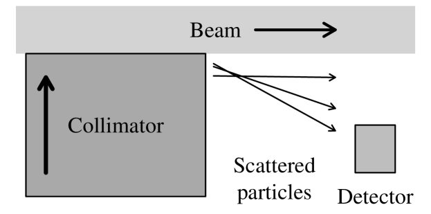

A schematic diagram of the apparatus is shown in Fig. 1 (top). All collimators except one are retracted. As the jaw of interest is moved in small steps (inward or outward), the local shower rates are recorded as a function of time. Collimator jaws define the machine aperture. If they are moved towards the beam center in small steps, typical spikes in the local shower rate are observed, which approach a new steady-state level with a characteristic relaxation time (Fig. 1, bottom). When collimators are retracted, on the other hand, a dip in losses is observed, which also tends to a new equilibrium level. By using the diffusion model presented below, the time evolution of losses can be related to the diffusion rate at the collimator position. By independently calibrating the loss monitors against the number of lost particles, halo populations and collimation efficiencies can also be estimated.
2.2 Model of loss rate evolution in a collimator scan
A diffusion model of the time evolution of loss rates caused by a step in collimator position was developed [12]. It builds upon the model of Ref. [6] and its assumptions: (1) constant diffusion rate and (2) linear halo tails within the range of the step. These hypotheses allow one to obtain analytical expressions for the solutions of the diffusion equation and for the corresponding loss rates vs. time. The present model addresses some of the limitations of the previous model and expands it in the following ways: (a) losses before, during, and after the step are predicted; (b) different steady-state rates before and after are explained; (c) determination of the model parameters (diffusion coefficient, tail population gradient, detector calibration, and background rate) is more robust and precise.
Following Ref. [6], we consider the evolution in time of a beam of particles with phase-space density described by the diffusion equation , where is the Hamiltonian action and the diffusion coefficient in action space. The particle flux at a given location is . During a collimator step, the action , corresponding to the collimator half gap at a ring location where the amplitude function is , changes from its initial value to its final value in a time . The step in action is . In the Tevatron, typical steps are in 40 ms, and the amplitude function is tens of meters. It is assumed that the collimator steps are small enough so that the diffusion coefficient can be treated as a constant in that region. If is constant, the local diffusion equation becomes . With these definitions, the particle loss rate at the collimator is equal to the flux at that location:
| (1) |
Particle showers caused by the loss of beam are measured with scintillator counters or ionization chambers placed close to the collimator jaw. The observed shower rate is parameterized as
| (2) |
where is a calibration constant including detector acceptance and efficiency and is a background term which includes, for instance, the effect of residual activation. Under the hypotheses described above, the diffusion equation can be solved analytically using the method of Green’s functions, subject to the boundary condition of vanishing density at the collimator and beyond. Details are given in Ref. [12].
Local losses are proportional to the gradient of the distribution function at the collimator. The gradients differ in the two cases of inward and outward step, denoted by the and subscripts, respectively:
| (4) | |||||
The parameters and are the slopes of the distribution function before and after the step, whereas varies linearly between and as the collimator moves. The parameter is defined as . The function is the S-shaped cumulative Gaussian distribution function: , , and .
The above expressions (Eqs. 2.2 and 4) are used to model the measured shower rates. Parameters are estimated from a fit to the experimental data. The background is measured before and after the scan when the jaws are retracted. The calibration factor is in general a function of collimator position, and can be determined independently by comparing the local loss rate with the number of lost particles measured by the beam current transformer. The parameters and depend on the steady-state loss rate levels before and after the step. The diffusion coefficient is mainly influenced by the measured relaxation time and by the value of the peak (or dip) in losses.
The model explains the data very well when the diffusion time is long compared to the duration of the step. The model can be extended by including a separate drift term (from the Fokker-Planck equation) or a nonvanishing beam distribution at the collimator. With this technique (collimator scans in small steps), the diffusion rate can be measured over a wide range of amplitudes. At large amplitudes, the method is limited by the vanishing beam population and by the fast diffusion times. The limit at small amplitudes is given by the level of tolerable loss spikes.
2.3 Results
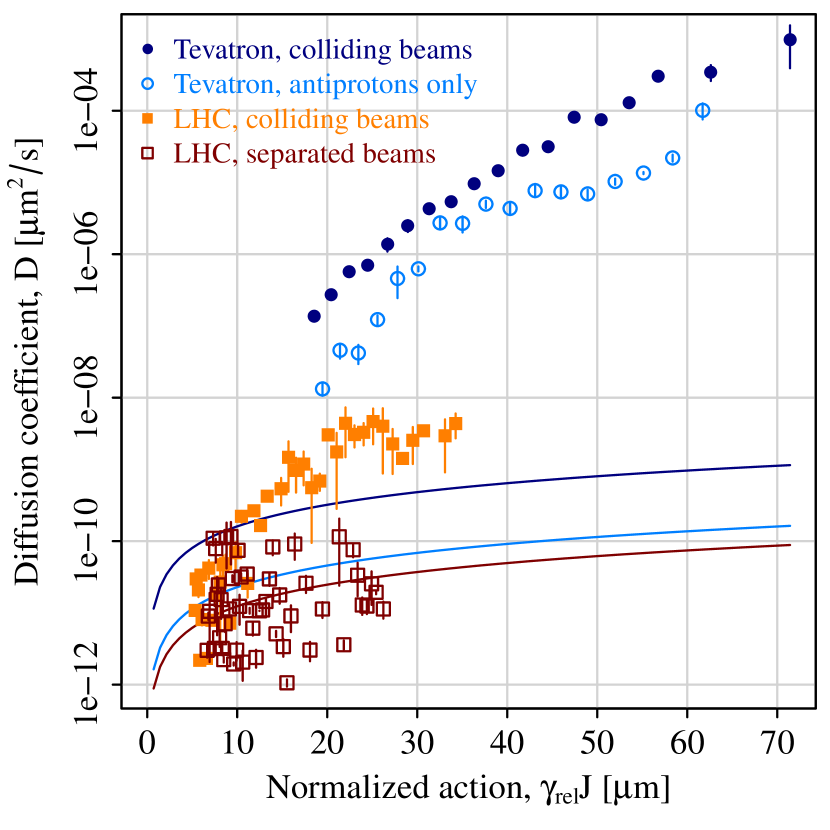
Figure 2 shows a comparison of beam halo diffusion measurements in the Tevatron and in the LHC. These data sets refer to vertical collimator scans. All Tevatron measurements were done on antiprotons at the end of regular collider stores, either in collisions (dark blue) or with only antiprotons in the machine (light blue). The LHC measurements were taken in a special machine study at 4 TeV with only one bunch per beam, first with separated beams (red) and then in collision (orange). To account for the different kinetic energies, diffusion coefficients are plotted as a function of vertical collimator action multiplied by the relativistic Lorentz factor . The continuous lines represent the diffusion coefficients calculated from the measured core geometrical emittance growth rates : . (In this particular data set, the synchrotron-light measurements were not sufficient to estimate emittance growth rates of colliding beams in the LHC).
In the LHC, separated beams exibit a slow halo diffusion, comparable with the emittance growth from the core. This can be interpreted as a confirmation of the extremely good quality of the magnetic fields in the machine. Collisions enhance halo diffusion in the vertical plane by about 1–2 orders of magnitude. In the Tevatron, the data suggests that beam halo diffusion is dominated by effects other than residual-gas scattering and beam-beam forces, pointing towards field nonlinearities and noise.
From the measured diffusion coefficients, estimates of impact parameters on the primary collimator jaws are possible [6]. One can also deduce the steady-state density of the beam tails, with a procedure that is complementary to the conventional static model based on counting the number of lost particles at each collimator step.
3 COLLIMATION WITH
HOLLOW ELECTRON BEAMS
In high-power accelerators, the stored beam energy can be large: about 2 MJ in the Tevatron, and several hundred megajoules in the LHC at nominal energies and intensities. Uncontrolled losses of even a small fraction of particles can damage components, cause magnets to lose superconductivity, and increase experimental backgrounds. Contributing to these losses is the beam halo, continuously replenished by beam-gas and intrabeam scattering, ground motion, electrical noise in the accelerating cavities, resonances and, in the case of colliders, beam-beam forces. The beam collimation system is therefore vital for the operation of high-power machines. Conventional collimation schemes include scatterers and absorbers, possibly including several stages. Primary collimators are the devices closest to the beam. They impart random transverse kicks, mainly due to multiple Coulomb scattering, to particles in the halo. The affected particles have increasing oscillation amplitudes and a large fraction of them is captured by the secondary collimators. These systems offer robust shielding of sensitive components. They are also very efficient in reducing beam losses at the experiments. A description of the Tevatron and LHC collimation systems can be found in Refs. [13, 14].
The classic multi-stage systems have some limitiations: a fraction of particles is always lost around the ring (leakage); collimator jaws have an electromagnetic impedance (wakefields); and high losses are generated during collimator setup when the jaws are moved inward to scrape away the halo. Another problem is beam jitter. The orbit of the circulating beam oscillates due ground motion and other vibrations. This translates into periodic bursts of losses at aperture restrictions. Hollow beams are a novel technique that addresses some of these limitations.
3.1 Concept
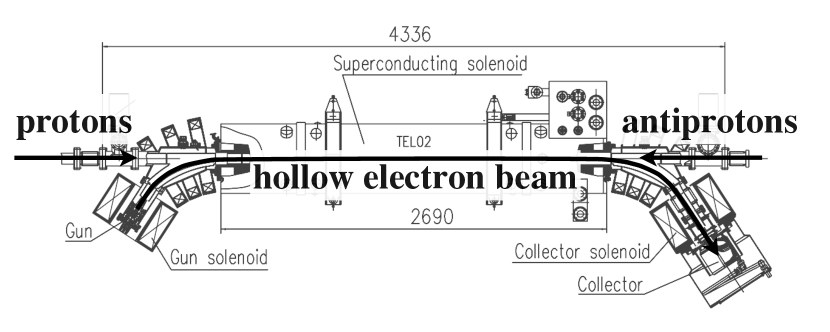
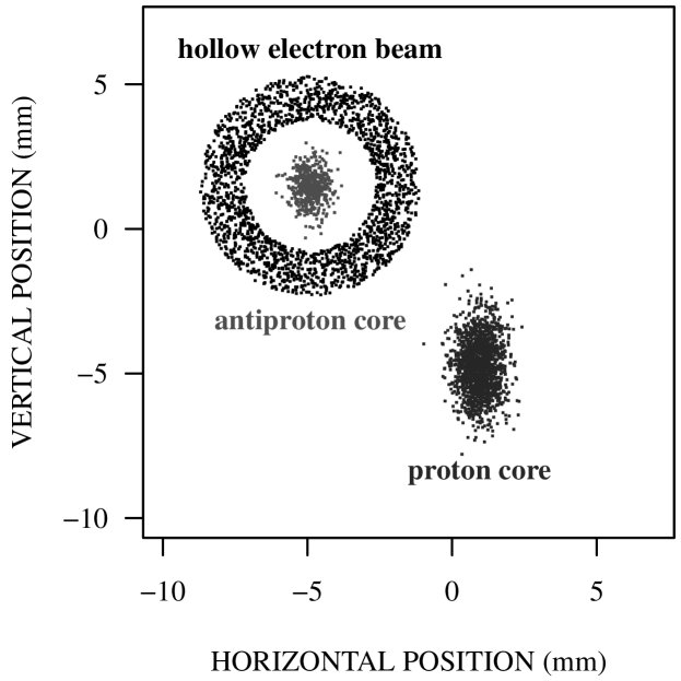
The hollow electron beam collimator is a cylindrical, hollow, magnetically confined, possibly pulsed electron beam overlapping with the beam halo [15, 16, 17, 10] (Fig. 3). Electrons enclose the circulating beam. Halo particles are kicked transversely by the electromagnetic field of the electrons. If the hollow charge distribution is axially symmetric, the core of the circulating beam does not experience any electric or magnetic fields. For typical parameters, the transverse kick given to 980-GeV protons or antiprotons in the Tevatron is of the order of . This is to be compared with the multiple-scattering random kick of from the primary tungsten collimators in the Tevatron. With the hollow electron lens, one aims at enhancing diffusion of the beam tails. This reduces their population in a controllable way. It also decreases the loss spikes caused by collimator setup, tune adjustments, and beam jitter.
A magnetically confined electron beam has several advantages. It can be placed very close to, and even overlap with the circulating beam. The transverse kicks are small and tunable, so that the device acts more like a “soft scraper” or a “diffusion enhancer,” rather than a hard aperture limitation. At even higher electron currents (which have not been demonstrated, yet) the electron beam could become an indestructible primary collimator. If needed, the electron beam can be pulsed to only affect a subset of bunches, or the abort gap (for setup and alignment purposes, for instance, or for abort-gap cleaning [18]). If faster particle removal is needed, the electron beam can be pulsed resonantly with the betatron oscillations. In the case of ion collimation, there is no nuclear breakup. Finally, the device relies on the estabilished technologies of electron cooling [19] and electron lenses [20, 21, 22]. One disadvantage may be the relative cost and complexity of the required components, such as superconducting solenoids, high-voltage modulators, and cryogenics.
3.2 Beam experiments at the Tevatron
The concept of hollow electron beam collimation was tested in the Fermilab Tevatron collider. Experiments in the Tevatron started in October 2010 and ended with the shutdown of the machine in September 2011. Many observables such as particle removal rates, effects on the core, diffusion enhancement, collimation efficiency and loss rate fluctuations were measured as a function of electron lens parameters: beam current, relative alignment, hole radius, pulsing pattern, and collimator configuration. Preliminary results were presented in Refs. [10, 23, 24, 25]. Here, we summarize the main observations: (a) compatibility with collider operations — the electron lens was routinely operated during regular collider stores without loss of luminosity; (b) reliable and reproducible alignment of the electron beam with the circulating beam; (c) smooth halo removal; (d) negligible effects on the core (no particle removal or emittance growth); (e) suppression of loss spikes due to beam jitter or tune adjustments; (f) increased collimation efficiency, defined as the ratio between local collimator losses and losses at the experiments; (g) transverse diffusion enhancement.
In the context of this paper, we would like to focus on the enhancement of beam halo diffusion. We are interested in how the hollow beam affects diffusion. For this purpose, new scintillator paddles were installed near one of the antiproton secondary collimators. These loss monitors were gated to individual bunch trains. With this device we could measure diffusion rates, collimation efficiencies and loss spikes simultaneously for the bunch trains affected by the electron beam and for the control bunch trains.
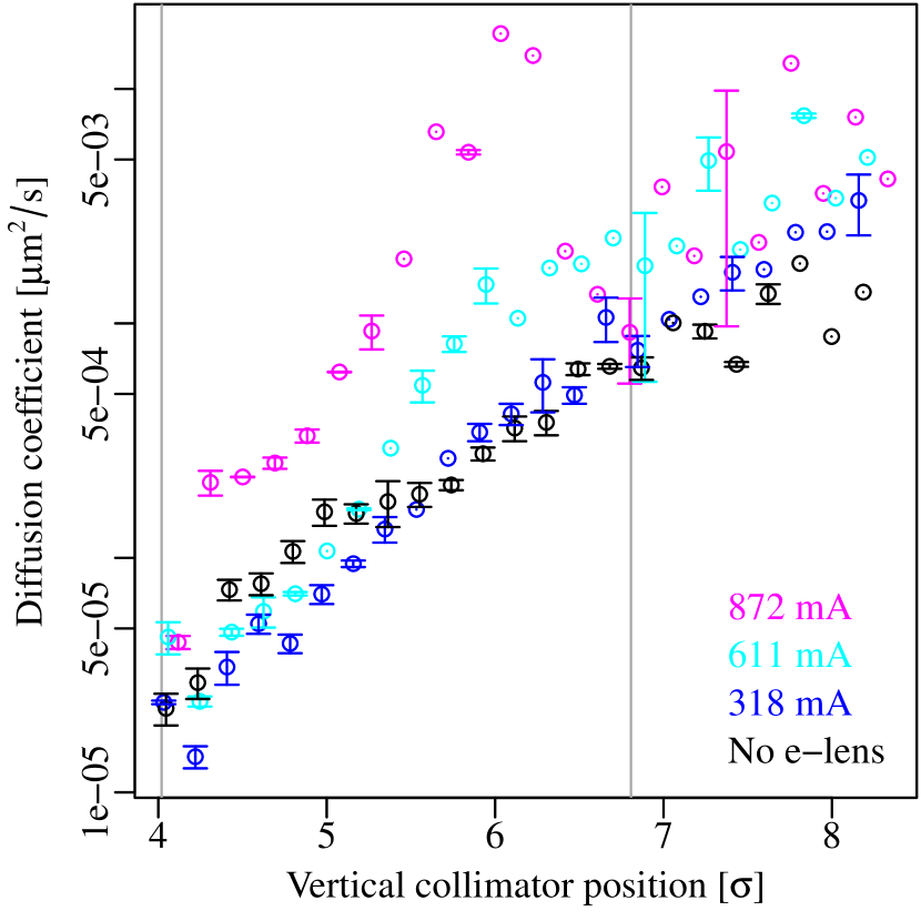
Figure 4 shows a measurement of the diffusion coefficient using the collimator-scan technique described in the first part of the paper. The measurement was taken at the end of a regular collider store. The diffusion coefficient is plotted as a function of the vertical collimator position (expressed in terms of the r.m.s. beam size ), for different values of the electron beam current. One can see a clear diffusion enhancement (up to 2 orders of magnitude for a beam current of 0.9 A) in the region of transverse space where the electron beam is present.
3.3 Applications to the LHC
Following the Tevatron experience, hollow electron beams are being considered as a complement to the LHC collimation system for operation at high intensities. The main feature of this novel technique is a safe and flexible control of beam tails. A first step towards this goal could be the installation of one of the existing Tevatron electron lenses in the SPS or in the LHC, where candidate locations have been identified.
To elucidate the dependence of the electron lens effect on the details of the machine, a campaign of numerical simulations is being carried out [26, 27]. The main goals are to understand the Tevatron observations, to develop complementary tools (Lifetrac and SixTrack), to check their consistency, and to extend the simulations to test scenarios in the SPS or in the LHC.
It is also desirable to develop larger electron guns, for two reasons: to achieve larger currents, and therefore extend the reach of the hollow lens; and to operate at higher solenoidal fields, improving the stability of the two-beam system. For these purposes, a new 1-inch hollow electron gun was built and is being tested at Fermilab.
4 CONCLUSIONS
Collimator scans are a sensitive tool for the study of halo dynamics. They allow one to investigate beam diffusion, populations, lifetimes, and collimation efficiencies as a function of transverse amplitude. Measurements of halo diffusion rates in the Tevatron and in the LHC were presented, quantifying the role of the different mechanisms dominating halo dynamics.
Hollow electron beams have been experimentally shown to be a safe and flexible technique for halo control in high-power accelerators. In this paper, their effect on halo dynamics in circular accelerators was emphasized. The characteristics of each individual machine must be taken into account to understand the details of their operation, but the technique appears to be applicable to the LHC and other accelerators.
References
- [1] A. J. Lichtenberg and M. A. Lieberman, Regular and Chaotic Dynamics (Springer-Verlag, New York, 1992).
- [2] T. Chen et al., Phys. Rev. Lett. 68, 33 (1992).
- [3] A. Gerasimov, FERMILAB-PUB-92-185 (1992).
- [4] F. Zimmermann, Part. Accel. 49, 67 (1995); SLAC-PUB-6634 (October 1994).
- [5] T. Sen and J. A. Ellison, Phys. Rev. Lett. 77, 1051 (1996).
- [6] K.-H. Mess and M. Seidel, Nucl. Instrum. Methods Phys. Res. A 351, 279 (1994); M. Seidel, PhD Thesis, Hamburg University, DESY-94-103 (June 1994).
- [7] L. Burnod, G. Ferioli, and J. B. Jeanneret, CERN-SL-90-01 (1990).
- [8] R. P. Fliller III et al., in Proceedings of the 2003 Particle Accelerator Conference (PAC03), Portland, OR, p. 2904.
- [9] G. Stancari et al., in Proceedings of the 2011 International Particle Accelerator Conference (IPAC11), San Sebastián, Spain, p. 1882.
- [10] G. Stancari et al., Phys. Rev. Lett. 107, 084802 (2011); arXiv:1105.3256 [phys.acc-ph].
- [11] G. Valentino et al., CERN-ATS-Note-2012-067 MD (2012); G. Stancari et al., FERMILAB-FN-0950-APC (2012).
- [12] G. Stancari, arXiv:1108.5010 [physics.acc-ph], FERMILAB-FN-0926-APC (2011).
- [13] N. Mokhov et al., JINST 6, T08005 (2011).
- [14] LHC Design Report, edited by O. Brüning et al., Vol. I, Ch. 18, CERN-2004-003 (2004).
- [15] V. Shiltsev, in Proceedings of the 3rd CARE-HHH-APD Workshop (LHC-LUMI-06), Valencia, Spain, p. 92, CERN-2007-002 (2007).
- [16] V. Shiltsev, in Proceedings of the CARE-HHH-APD Workshop (BEAM07), Geneva, Switzerland, p. 46, CERN-2008-005 (2007).
- [17] V. Shiltsev et al., in Proceedings of the 2008 European Particle Accelerator Conference (EPAC08), Genoa, Italy, p. 292, FERMILAB-CONF-08-184-APC (2008).
- [18] X.-L. Zhang et al., Phys. Rev. ST Accel. Beams 11, 051002 (2008).
- [19] V. V. Parkhomchuk and A. N. Skrinsky, Rev. Accel. Sci. Tech. 1, 237 (2008).
- [20] V. Shiltsev et al., Phys. Rev. Lett. 99, 244801 (2007).
- [21] V. Shiltsev et al., New J. Phys. 10, 043042 (2008).
- [22] V. Shiltsev et al., Phys. Rev. ST Accel. Beams 11, 103501 (2008).
- [23] G. Stancari et al., in Proceedings of the 2011 Particle Accelerator Conference (PAC11), New York, NY, p. 370, FERMILAB-CONF-11-058-AD-APC (2011).
- [24] G. Stancari et al., in Proceedings of the 2011 International Particle Accelerator Conference (IPAC11), San Sebastián, Spain, p. 1939, FERMILAB-CONF-11-412-AD-APC (2011).
- [25] G. Stancari, in Proceedings of the 2011 Meeting of the Division of Particles and Fields of the American Physical Society (APS/DPF 2011), Providence, RI, arXiv:1110.0144 [physics.acc-ph], FERMILAB-CONF-11-506-AD-APC.
- [26] I. Morozov et al., in Proceedings of the 2012 International Particle Accelerator Conference (IPAC12), New Orleans, LA, p. 94.
- [27] V. Previtali et al., in Proceedings of the 2012 International Particle Accelerator Conference (IPAC12), New Orleans, LA, p. 1113.