High- impurity photon states bounded by a photonic-band-pseudogap
in an optically-thick photonic-crystal slab
Abstract
We show that, taking a two-dimensional photonic-crystal slab system as an example, surprisingly high quality factors () over are achievable, even in the absence of a rigorous photonic-band-gap. We find that the density of in-plane Bloch modes can be controlled by creating additional photon feedback from a finite-size photonic-crystal boundary that serves as a low-Q resonator. This mechanism enables significant reduction in the coupling strength between the bound state and the extended Bloch modes by more than a factor of 40.
pacs:
42.60.Da, 42.70.Qs, 42.50.PqSignificant reduction in the radiation rate of a point-like emitter can be achieved by setting up mirrors around it,Purcell (1946) or by employing photonic crystals (PhCs),Yablonovitch (1987); John (1987) which is a photonic analogue of atomic crystals for electron waves.Joannopoulos et al. (2008) It has long been believed that the existence of the photonic-band-gap (PBG) is essential to achieving a spatially localized high- electromagnetic bound state using a PhC cavity. Thus, most efforts so far have focused on artificial dielectric structures possessing a PBG.Yablonovitch (1993); Noda et al. (2000); Chow et al. (2000); Maldovan and Thomas (2004) Donor- or acceptor-like impurity photon states can be formed at the location of a crystal defect.Yablonovitch et al. (1991) Such a localized state (with small mode volume, ) has drawn much attention in the context of cavity quantum electrodynamics (cQED) experimentsYoshie et al. (2004); Noda et al. (2007) where the use of high cavities are essential to enhancing light-matter interaction.
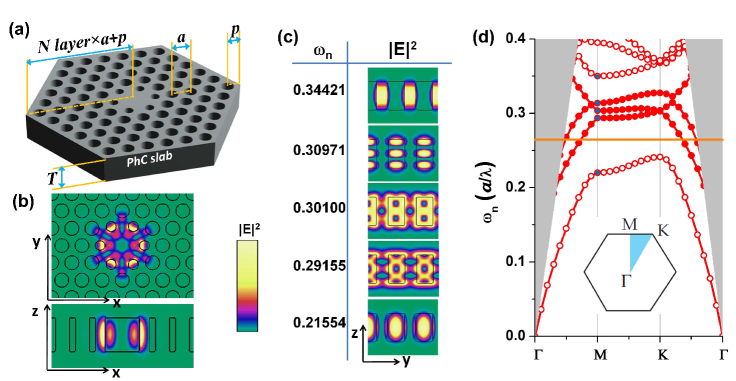
Due to fabrication related difficulties, three-dimensional (3-D) PhCs have been replaced with a lower dimensional counterpart relying on index guiding in one or two dimensions. Often, this assumes the from of a thin dielectric slabJohnson et al. (1999), whose thickness () is roughly equal to half the effective wavelength () in order to optimize the size of the in-plane PBG. One representative such a design is shown in Fig. 1(a) and (b). Note that a 2-D PhC with the triangular-lattice of air-holes supports the PBG only for even guided modes, where the symmetry is defined with respect to the mirror plane at . However, this incomplete PBG does not preclude the possibility of high- defect states, because the same mirror symmetry ensures that the defect mode with the even symmetry will be completely decoupled from all odd guided modes. Lowering the dimensionality often creates new symmetries that can be exploited, making the condition for localized photon states less stringent.
It is well established that an optically-thick PhC slab does not support any PBG for both even and odd symmetriesJohnson et al. (1999); Kim et al. (2012a). As an example, in Fig. 1(d), we present a photonic band structure (- diagram) for even Bloch modes in a thick PhC slab with . The formation of the PBG is hindered by the higher-order slab modes lying between the 1st and the 5th bands. Note that the energy gap defined by the 1st and the 5th bands () will remain more or less constant as increases and, in the limit of , will approach the PBG of an ideal 2-D PhCJohnson et al. (1999). Also note that, though all bands, , shown in Fig. 1(d) are mutually orthogonal, the bound state in a defect region, , in general, can couple to any of the higher-order Bloch modes. However, this coupling strength, Haus (1984), shouldn’t be strong, because resembles of the 1st band. In this sense, any optically-thick PhC slab bears a pseudo-PBG. Similar pseudo-energy gap in solid state physics can create resonance statesMadelung (1978). Here, the photonic counterpart can be easily manipulated with high precision by means of the mature modern nanofabrication technology.
In this Letter, we will show how can be controlled by setting up simple mirror boundaries around the finite size PhC resonator [Fig. 1(a)]. The additional boundary conditions imposed by the mirrors can alter the density of Bloch states in the momentum space (-space). Thus, in relation to the spectrum of Srinivasan and Painter (2002), can experience significant change. We note that the situation is analogous to the well-known cQED example of a point dipole source ( the hexapole mode) in an optical resonator ( the low- resonator defined by the boundary termination)Hinds (1994).
We perform fully-vectorial 3-D numerical simulations using the finite-difference time-domain method (FDTD) to understand the mutual interaction between and . First, we study the energy decay rate () of the hexapole modeRyu et al. (2003) shown in Fig. 1(b). The total decay rate () can be decomposed into the decay rates into the horizontal direction () and the out-of-plane direction (). Then, is translated into factor through . Thus, Kim et al. (2012a). Note that we set up detection planes for the Poynting energy flux () away from the mirror boundary, so that accounts for the reflection/transmission at the PhC-air discontinuity.
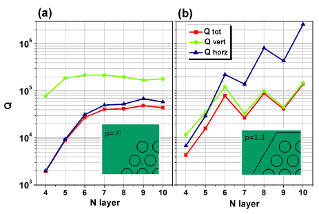
In Fig. 2, we consider the two boundary terminations of and . For , tends to be saturated by ; approaches as layer 8Kim et al. (2012a). In fact, this particular choice of the boundary termination approximately ensures negligibly small reflection off the interface. Alternatively, we can simulate the transparent boundary condition by overlapping the perfectly matched layer in the FDTD with the PhC air-holesKoshiba et al. (2001), which results in the similar saturated of 60,000 ().
Usually, the reflection coefficient at the PhC-air boundary is not so large as 0.50.6Istrate et al. (2005). However, drastically different behaviors can be seen by forming simple mirrors with [Fig. 2(b)]. (i) All values strongly modulate with . (ii) can be brought up to a surprisingly high value of at = 10. This implies that can be reduced by more than a factor of 40 compared with the case of minimal reflection (). (iii) Since , now the hexapole mode emits more photons into the out-of-plane direction. Interestingly, all s modulate in the same fashion; whenever is peaked, so is . Therefore, the abrupt boundary termination does not simply redirect the in-plane guided energy into the out-of-plane radiation. Rather, there should be a common physical principle for the observed enhancement and suppression. Moreover, note that the maximum of in the present case can be further increased by employing a higher cavity mode. Also note that of the hexapole mode is slightly lowered by the use of finite space grids () used in the FDTD simulationKim et al. (2006).
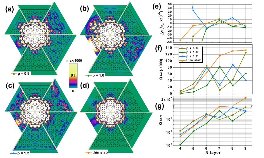
More detailed analyses are performed as we finely tune the mirror boundary conditions. Specifically, we tune in the range of as a means to control the phase shift () upon reflection. Here, we will provide direct graphical evidence for the enhancement/suppression of the in-plane Bloch modes. In order to visualize the very weak near-fields in the outskirt regions, we adopt the saturated color scheme in which of the intensity maximum is taken as the upper bound. In Fig. 3(a)-(c), we present of the hexapole mode for three different , , and . We take only one-sixth area (cut by the two - lines) of the hexapole mode profile for each , then combined with plots of different s to create a one image filling upto 360∘. We also provide a similar plot for a PBG-confined hexapole mode in Fig. 3(d), corresponding to a slab thickness of . For quantitative analyses, we also provide graphs for [Fig. 3(f)] and [Fig. 3(g)] as well as the resonance frequency shift [Fig. 3(e)].
We find that, at ( , ) = (9, ), is almost completely suppressed, which is comparable with that of the PBG-confined case shown in Fig. 3(d). On the other hand, at certain combinations of ( , ), becomes quite strongly pronounced; for example, see (7, ), (8, ), and (7, ). For small such as at ( , ), it seems natural to have more intense photon tunneling than the equivalent PBG-confined case. However, by slightly tuning , the strong in-plane loss in the previous case can be greatly reduced by more than a factor of 10, whose resultant and can be higher than those of the PBG-confined casethi . This result may find a practical importance in applications where a device miniaturization is required while keeping reasonably high.
We find that variations can explain peaks and dips observed in or . We also note that the more intensified in the outskirt region can contribute to the excessive scattering losses into the vertical direction, thereby lowering . In short, what we have shown here is that strongly depends on the detailed boundary conditions. obviously depends on the size of the hexagonal boundary, which determines the phase thickness of the 2-D cavity. It is also understandable that is a very critical parameter controlling the density of in-plane Bloch modes, as has been seen in many cQED examples of an atom and a cavity. Further evidence of this analogy can be found in Fig. 3(e), which reports the fractional frequency shift. Even using sufficiently thick PhC mirrors with , the thick-slab cases show noticeable modulations in order of , while the PBG-confined case does not. These energy-level shiftsHinds (1994) are signatures of the coupling between and and can be explained in terms of Haus (1984).
Though the FDTD provides very accurate first-principle means to understand the modulation, we have not been quite convinced as to how the simple boundary termination (hence the low-) can enable such large modulations in (and as well). Therefore, it would be instructive to develop a simple model in the spirit of the coupled mode theory (CMT)Haus (1984); Fan et al. (2003). To begin, we would like to note that the in-plane hexapole mode profile, , can be approximated in terms of the three -point wavevectors of , , and with . For example, with a correction factor Painter and Srinivasan (2003). For our hexapole mode, is based on the -space intensity distribution, Kim et al. (2006). This is the reason the outskirt region of the hexapole mode resembles the -point Bloch modesKim et al. (2004).
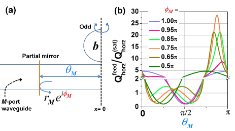
To simplify our CMT model, we assume that the hexapole mode couples only to the six -point wavevectors, (, , , , , ), where is a scale factor as evidenced from the photonic band structure in Fig. 1(d). Now we emphasize that these -point wavevectors () are closed upon reflections at the six hexagonal facets. Thus, we may consider the whole set of wavevectors, , as a channel or a port in the CMT formulation [Fig. 4(a)]. Under these assumptions, our hexapole mode can be viewed as side-coupled to the portsid . Then, the time evolution of the hexapole mode’s energy amplitude () can be described by
| (1) |
where the last term describes the total incoming power as a result of the feedback by the boundary termination. We assume that is measured at the inner boundary of the partial mirror shown in Fig. 4(a) and consists of the Bloch waves with . The CMT states that cannot be arbitrarily determined but rather it should be connected by the decay rate into the waveguide port such that .
When the effect of the photon feedback is weak as in the case of , we can set in Eq. 1. Then, decays exponentially with . However, when there is a feedback mechanism, is not a constant but varies with and (reflection phase). For this general situation, we need additional set of equations, which can be derived from the CMTManolatou et al. (1999). For example, the outgoing power () and the incoming power () are related each other by through
| (2) |
We define the scattering matrix of the partial mirror such that . Then, the modified () can be written using the definition of ( [total energy stored in the resonator][total power loss into the port]),
| (3) |
In general, (the resonance frequency in the presence of the feedback) differs from the original as we have seen from the FDTD result in Fig. 3(e). However, we can assume since the fractional change in is much less than 1%. Note that the partial mirror is assumed to be lossless such that .
After solving and for , we obtain the expression for the enhancement, (),
| (4) |
Fig. 4(b) shows plots of Eq. 4 for several values, while is fixed at 0.6. The model also expects drastic modulations in depending where we locate the resonator with respect to the envelop of the low- Fabry-Perot type resonator. For example, when , enhancement is maximized to be about 5 at (=effective half wavelength), which can be understood considering that at . Interestingly, tuning slightly can greatly improve the enhancement; results in the maximum very close to 30. We also find that the tuning inevitably alters the optimal for , which agrees with the FDTD results in Fig. 3; the small tuning in changes the optimal for .
It should be noted that we have assumed only one -port and such a large enhancement holds true only for that port. However, if the defect state could excite many in-plane Bloch waves with different wavevectors thereby creating many -ports, the overall enhancement contributed from different -ports will be averaged out to be 1 as Eq. 4 expects. For example, multiple ports might be involved if were too thick (since this would allow more higher-order slab modes with many s) or if the boundary termination would not retain the hexapole symmetry (since cannot be conserved upon reflections).
In summary, we study a quasi-bound photon state within a PhC that does not posses a rigorous PBG. We show that the density of in-plane Bloch modes can be controlled by the termination of the finite-size PhC. The coupling strength between the bound state and the extended Bloch modes can be reduced by more than a factor of 40 in the case of a thick PhC slab. The air-suspended slab structure assumed in this study may appear impractical. However, low index cladding material can be placed underneath as a supporting structure or a metal cladding to the sides of the hexagonal boundary can be used a clampHuang et al. (2010), which could also be used as an electrode for current injection. By removing the thickness constraint of , many unconventional cavity designs which were previously discarded because they cannot support a PBG can now be reconsidered, such as the use of a thick-slab for the design of current-injection nanolasersKim et al. (2012b).
Acknowledgements.
This work was supported by the Defense Advanced Research Projects Agency under the Nanoscale Architecture for Coherent Hyperoptical Sources program (W911NF-07-1-0277) and by the National Science Foundation under NSF CIAN ERC (EEC-0812072). A. Homyk appreciates the generous support of the ARCS Foundation.References
- Purcell (1946) E. M. Purcell, Phys. Rev. 69, 681 (1946).
- Yablonovitch (1987) E. Yablonovitch, Phys. Rev. Lett. 58, 2059 (1987).
- John (1987) S. John, Phys. Rev. Lett. 58, 2486 (1987).
- Joannopoulos et al. (2008) J. D. Joannopoulos, S. G. Johnson, J. N. Winn, and R. D. Meade, Photonic Crystals: Molding the Flow of Light (Princeton University Press, Princeton, NJ, 2008), 2nd ed.
- Yablonovitch (1993) E. Yablonovitch, J. Opt. Soc. Am. B 10, 283 (1993).
- Noda et al. (2000) S. Noda, K. Tomoda, N. Yamamoto, and A. Chutinan, Science 289, 604 (2000).
- Chow et al. (2000) E. Chow, S. Lin, S. Johnson, P. Villeneuve, J. Joannopoulos, J. Wendt, G. Vawter, W. Zubrzycki, H. Hou, and A. Alleman, Nature 407, 983 (2000).
- Maldovan and Thomas (2004) M. Maldovan and E. L. Thomas, Nat. Mater. 3, 593 (2004).
- Yablonovitch et al. (1991) E. Yablonovitch, T. J. Gmitter, R. D. Meade, A. M. Rappe, K. D. Brommer, and J. D. Joannopoulos, Physical Review Letters 67, 3380 (1991).
- Yoshie et al. (2004) T. Yoshie, A. Scherer, J. Hendrickson, G. Khitrova, H. M. Gibbs, G. Rupper, C. Ell, O. B. Shchekin, and D. G. Deppe, Nature 432, 200 (2004).
- Noda et al. (2007) S. Noda, M. Fujita, and T. Asano, Nature 1, 449 (2007).
- Johnson et al. (1999) S. G. Johnson, S. Fan, P. R. Villeneuve, J. D. Joannopoulos, and L. A. Kolodziejski, Physical Review B 60, 5751 (1999).
- Kim et al. (2012a) S.-H. Kim, J. Huang, and A. Scherer, Opt. Lett. 37, 488 (2012a).
- Haus (1984) H. A. Haus, Waves and Fields in Optoelectronics (Prentice-Hall, Englewood Cliffs, N. J., 1984).
- Madelung (1978) O. Madelung, Introduction to Solid-State Theory (Springer-Verlag, Berlin, 1978), chap. 14.
- Srinivasan and Painter (2002) K. Srinivasan and O. Painter, Opt. Express 10, 670 (2002).
- Hinds (1994) E. A. Hinds, in Cavity Quantum Electrodynamics (Academic Press, Inc, Orlando, 1994), edited by P. R. Berman.
- Ryu et al. (2003) H.-Y. Ryu, M. Notomi, and Y.-H. Lee, Appl. Phys. Lett. 83, 4294 (2003).
- Koshiba et al. (2001) M. Koshiba, Y. Tsuji, and S. Sasaki, Microwave and Wireless Components Letters, IEEE 11, 152 (2001).
- Istrate et al. (2005) E. Istrate, A. A. Green, and E. H. Sargent, Phys. Rev. B 71, 195122 (2005).
- Kim et al. (2006) S.-H. Kim, S.-K. Kim, and Y.-H. Lee, Phys. Rev. B 73, 235117 (pages 13) (2006).
- (22) For the thin PhC slab, we find that causes excessive scattering losses at the termination boundaries, resulting in the lower than case. For fair comparions between thin- and thick slabs, we assume both modes oscillate at approximately same resonant wavelengths of 1300 nm, which can be achieved by choosing of the thin-slab and the thick-slab to be 410 nm and 350 nm, respectively.
- Fan et al. (2003) S. Fan, W. Suh, and J. D. Joannopoulos, J. Opt. Soc. Am. A 20, 569 (2003).
- Painter and Srinivasan (2003) O. Painter and K. Srinivasan, Phys. Rev. B 68, 035110 (2003).
- Kim et al. (2004) G.-H. Kim, Y.-H. Lee, A. Shinya, and M. Notomi, Opt. Express 12, 6624 (2004).
- (26) The side-coupling configuration may describe the situation better than the butt-coupling, because 1) the point-like defect structure occupies only a small fraction of the entire 2-D cavity and 2) the 2-D Bloch waves rather freely move from the left side to the right side without being assisted by the resonance of the defect.
- Manolatou et al. (1999) C. Manolatou, M. J. Khan, S. Fan, P. R. Villeneuve, H. A. Haus, and J. D. Joannopoulos, IEEE Journal of Quantum Electronics 35, 1322 (1999).
- Huang et al. (2010) J. Huang, S.-H. Kim, and A. Scherer, Opt. Express 18, 19581 (2010).
- Kim et al. (2012b) S.-H. Kim, J. Huang, and A. Scherer, J. Opt. Soc. Am. B 29, 577 (2012b).