Three dimensional tracking of gold nanoparticles using digital holographic microscopy
Frédéric Verpillata, Fadwa Jouda, Pierre Desbiollesa and Michel Grossb
a Laboratoire Kastler Brossel, Ecole Normale Supérieure, UPMC, 24 Rue Lhomond, 75005
Paris, France;
b Laboratoire Charles Coulomb, Université Montpellier II, Place Eugène Bataillon, 34095
Montpellier, France;
Abstract
In this paper we present a digital holographic microscope to track gold colloids in three dimensions. We report observations of 100 nm gold particles in motion in water. The expected signal and the chosen method of reconstruction are described. We also discuss about how to implement the numerical calculation to reach real-time 3D tracking.
1 Introduction
The tracking of nano-scale biological markers in motion is a challenging project, that could lead to a better understanding of dynamics in biological systems. Since digital holography gives access to the whole light field in a volume from a single hologram [1, 2], this technique is suitable to reconstruct the field scattered by gold particles in three dimensions, and then determine their positions. This localization can be done without any mecanical scanning of the setup. The 3D tracking in digital holography was demonstated for micron-size particles in several publications with in-line holography [3, 4, 5, 6]. The observation of nano-scale gold particles was also demonstrated in off-axis holography by Atlan et al.[7], and on the membrane of a living cell by Joud et al. [8]. Nano particles could be observed with the combination of off-axis geometry and phase-shifting technique [9], that achieves almost the theoretical noise level [10]. In this paper, we present first our digital holographic microscope, then we explain the reconstruction method. Some results of 3D tracking of 100 nm nano-beads are presented.
2 Experimental setup
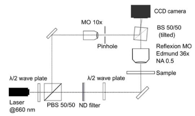
We chose to track 100nm gold beads in Brownian motion in water. This particles are good light scatterers because their optical index in visible light is very low. Moreover they are non cyto-toxic and chemically inert [11]. The sample is prepared using a 400 m deep chamber between two cover glasses filled with a nano-beads solution. The experimental setup is shown on the figure 1. The optical setup use a 100 mW DPSS laser emitting at 660 nm. The laser beam is splitted with a polarizing beam splitter. We adjust the ratio of energy between both beams with an half-wave plate placed before the splitter. The first beam, called illumination beam, is focalised on the sample. The second beam, called reference beam, is spatially filtered and expanded in a way to cover all the CCD chip. A dark-field microscope objective from Edmund Optic (NA = 0.5 and 36 magnification) collects the scattered light and blocks the illumination beam. This dark field configuration is necessary to avoid the saturation of the CCD chip : the Rayleigh-Mie scattering model [12] gives a cross section of 0.015 m2 for a 100 nm diameter gold particle at 660 nm. During 1 ms, the number of incident photons is typically 1014 photons at 660 nm, and the area of the illumination beam s waist is m2. The number of scattered photons by the nano-bead collected through a numerical aperture of 0.5 is equal to photon during 1 ms. The ratio of number of photons between the illumination beam and the scattered light is about , so it s not possible to record the scattered signal on our 16 bits CCD chip without blocking the illumination beam. The dark field objective allows to use the full dynamic of the CCD chip to record the low scattered signal. A non-polarizing beam splitter behind the microscope objective combines the reference and the scattered signal. This splitter is titled of a few degrees to be in off-axis geometry [13]. The interference pattern is recorded on the 16 bits CCD chip of pixels.
The observation of particles in motion imposes to limit the exposition time in order to limit the blurring of the signal. The magnification calibration of our setup gives a lateral pixel size of 160 nm. In our case, the diffusion constant of the Brownian motion is equal to according to the Stokes-Enstein law. So the exposition time must be lower than 3 ms to avoid that the signal is shiffted by one pixel. The exposition time of our camera can be set under this limit, but the acquisition period during 2 frames is limited to 80 ms. The travel of 100 nm particles in water during this period is too long to use the phase-shifting technique in order to improve the signal-to-noise ratio [9, 14].
3 3D reconstruction of the scattered light
The camera record for each frame an intensity described in the following equation :
| (1) |
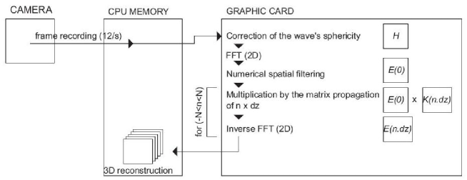
where and are respectively the intensity of the reference and the scattering light. and are the respective fields. The tilted beam splitter which combines the two fields adds a spatial frequency on the cross terms of interference (the third and fourth terms of the equation (1)). The effect is that these two terms can be separated in the Fourier space of the holograms. Figure 2 summarizes the steps of our reconstruction. First we multiply the hologram by a complex phase matrix where is the wavelength and the distance between the CCD and the output pupil of the microscope objective. This operation is similar to a back-propagation of the hologram to the output plane of the objective. This propagation compensates the sphericity of the wave added by the objective. Then we calculate the Fast-Fourier Transform (FFT) of the corrected hologram. In the Fourier plane, the two first term of equation 1 are in the center, while the cross terms are respectively centered on the frequency added by the off-axis geometry and its complex conjugate. We numerically filter the term of equation 1 with a circular mask of radius equal to the apparent radius of the output pupil. The filtered map of the spatial frequencies () obtained is multiplied by the following matrix of propagation :
| (2) |
where is the arbitrary step of axial propagation (typically 100 nm) and an integer. Then we calculate the inverse FFT. The result is the reconstruction of the field at the distance . We repeat this multiplication by varying the integer n to reconstruct the volume. We get a stack of lateral sections spaced by . The positions of the scatterers are determined by the local maximum of the intensity of the whole reconstructed field.
All this numerical reconstruction is implemented on a graphic card unit. We developp our algoritm with the Nvidia CUDA architecture to parallelize all the calculation on the 448 cores of a Nvidia Geforce GTX 470 card. All the steps of the reconstructions, except for the FFTs, need multiplication pixels to pixels and not matrix multiplication. This kind of operation are perfectly adapted for parallelization on graphic cores [15, 16, 17, 18]. The FFT steps are made with the CUFFT library. We divided the time of reconstruction by a factor 30 compare to the same reconstruction made only on the CPU (double quad-core Intel Xeon E5520 at 2.27 GHz). We developped a software for live visualisation of reconstruction using OpenGL library to display the datas calculated on the graphic card.
4 Current results
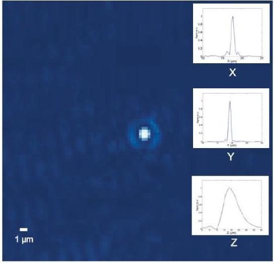
We are able now to observe 100nm gold nano particles in Brownian motion during few tens of positions. After that we generally lose the targets. The figure 3 shows the observation we are able to do in the present state of the setup. We see on the figure the lateral section where the intensity of the scattered light by the nano-bead is maximum. The PSF of the reconstructed field is plotted for and directions. The lateral PSF width is equal to 1 m, and the axial width is equal to 14 m. The signal-to-noise ratio of the reconstruction is better than 100. These results are obtained with an exposition time of only 1ms and an acquisition period of 80 ms between two frames.
5 Conclusion
We report in this paper the present performance of our digital holographic microscope. It consists of a Mach-Zender setup in off-axis geometry. A dark field microscope objective collects the light scattered by nano-sized gold particles, which interferes with the reference plane wave on the CCD camera. The scattered light field is numerically propagated from the interference pattern. We used our own algorithm based on the CUDA architecture to reduce the calculation time. The improvement clearly shows that this technology is a very promising tool for digital holography. We are able now to localize 100 nm gold nano particles in Brownian motion from holograms exposed during 1 ms. We expect to obtain similar performance for gold particles in a crowed medium or in a living cell in order to study the diffusion law in these specific media.
References
- [1] U. Schnars. Direct phase determination in hologram interferometry with use of digitally recorded holograms. JOSA A, 11(7):2011–2015, 1994.
- [2] E. Leith and J. Upatnieks. Wavefront reconstruction photography. Physics Today, 18:26, 1965.
- [3] F.C. Cheong, B.J. Krishnatreya, and D.G. Grier. Strategies for three-dimensional particle tracking with holographic video microscopy. Optics express, 18(13):13563–13573, 2010.
- [4] J. Sheng, E. Malkiel, and J. Katz. Digital holographic microscope for measuring three-dimensional particle distributions and motions. Applied optics, 45(16):3893–3901, 2006.
- [5] M. Speidel, L. Friedrich, and A. Rohrbach. Interferometric 3d tracking of several particles in a scanning laser focus. Optics express, 17(2):1003–1015, 2009.
- [6] W. Xu, MH Jericho, HJ Kreuzer, and IA Meinertzhagen. Tracking particles in four dimensions with in-line holographic microscopy. Optics letters, 28(3):164–166, 2003.
- [7] M. Atlan, M. Gross, P. Desbiolles, É. Absil, G. Tessier, and M. Coppey-Moisan. Heterodyne holographic microscopy of gold particles. Optics letters, 33(5):500–502, 2008.
- [8] N. Warnasooriya, F. Joud, P. Bun, G. Tessier, M. Coppey-Moisan, P. Desbiolles, M. Atlan, M. Abboud, and M. Gross. Imaging gold nanoparticles in living cell environments using heterodyne digital holographic microscopy. Optics Express, 18(4):3264–3273, 2010.
- [9] T. Zhang and I. Yamaguchi. Three-dimensional microscopy with phase-shifting digital holography. Optics letters, 23(15):1221–1223, 1998.
- [10] M. Gross and M. Atlan. Digital holography with ultimate sensitivity. Optics letters, 32(8):909–911, 2007.
- [11] P.K. Jain, K.S. Lee, I.H. El-Sayed, and M.A. El-Sayed. Calculated absorption and scattering properties of gold nanoparticles of different size, shape, and composition: applications in biological imaging and biomedicine. The Journal of Physical Chemistry B, 110(14):7238–7248, 2006.
- [12] H.C. van de Hulst. Light scattering by small particles. Dover publications, 1981.
- [13] E. Cuche, P. Marquet, and C. Depeursinge. Spatial filtering for zero-order and twin-image elimination in digital off-axis holography. Applied Optics, 39(23):4070–4075, 2000.
- [14] I. Yamaguchi, J. Kato, S. Ohta, and J. Mizuno. Image formation in phase-shifting digital holography and applications to microscopy. Applied Optics, 40(34):6177–6186, 2001.
- [15] B. Samson, F. Verpillat, M. Gross, and M. Atlan. Video-rate laser doppler vibrometry by heterodyne holography. Optics letters, 36(8):1449–1451, 2011.
- [16] T. Shimobaba, Y. Sato, J. Miura, M. Takenouchi, and T. Ito. Real-time digital holographic microscopy using the graphic processing unit. Optics express, 16(16):11776–11781, 2008.
- [17] L. Ahrenberg, A.J. Page, B.M. Hennelly, J.B. McDonald, and T.J. Naughton. Using commodity graphics hardware for real-time digital hologram view-reconstruction. Display Technology, Journal of, 5(4):111–119, 2009.
- [18] H. Kang, F. Yaraş, and L. Onural. Graphics processing unit accelerated computation of digital holograms. Applied optics, 48(34):H137–H143, 2009.