Variable Ultra-broadband and Narrowband Composite Polarization Retarders
Abstract
We propose and experimentally demonstrate novel types of composite sequences of half-wave and quarter-wave polarization retarders, either permitting operation at ultra-broad spectral bandwidth or narrow bandwidth. The retarders are composed of stacked standard half-wave retarders and quarter-wave retarders of equal thickness. To our knowledge, these home-built devices outperform all commercially available compound retarders, made of several birefringent materials.
260.5430, 260.1440, 260.2130.
I Introduction
Optical half-wave and quarter-wave retarders Hecht based on birefringent materials are standard optical components with innumerous applications. Light passing through a birefringent material with the optical axis aligned perpendicular to the beam propagation direction experiences a phase shift between the two orthogonal polarization directions. Here, is the light wavelength, is the thickness of the birefringent material and are the refractive indices of the (extra-)ordinary rays. The most common types of retarders are half-wave plates (HWPs) with and quarter-wave plates (QWPs) with , where . These wave plates are divided into multi-order wave plates (with ) and zero-order wave plates (with ). In the optical region, zero-order wave plates are typically constructed by combining two multi-order plates with crossed optical axes to yield the desired phase shift. A single zero-order wave plate would be very thin and too fragile.
Both zero- and multi-order wave plates show dispersion, i.e., the phase shift (retardation) depends on the wavelength of the incident light. This effect is more pronounced for multi-order than for zero-order plates. However, many applications require achromatic (broadband, BB) wave plates, which show negligible dispersion over a large wavelength range. As examples for applications of BB plates we note, e.g., terahertz (THz) time-domain spectroscopy GKE90 ; MG06 , microwave polarimetry HHJ05 ; PSA06 ; MHA09 , or achromatic polarization rotators in liquid crystal devices ZKP00 ; LSK04 . There are several types of achromatic wave plates. Compound-type achromatic wave plates utilize two different materials. If the wavelength-dependent difference of the refractive indices of the two materials (almost) cancel each other, the compound wave plate is achromatic over a larger wavelength range D67 ; B71 ; B72 . Stacked-type achromatic wave plates use a stack of (conventional) wave plates P55b ; K59 ; T75 ; MH68 ; LSK04 . Here, the optical axis of each wave plate is rotated with respect to the other plates to create a specific sequence of phase shifts. Appropriate choice of the phase shift sequences permits (almost) achromatic retardation over a large bandwidth or for a larger set of discrete wavelengths.
Recently, Ardavan pointed out A07b that states from the Poincar space (which are typically used for the description of photon polarizations) can be mapped onto the Bloch space (which is typically used for the description of quantum state dynamics of two level systems, e.g. spin particles). This allows transfer of concepts from the field of coherent interactions between light and quantum systems to the field of polarization optics. In particular, we draw our attention now to techniques for error correction during quantum state transfer W94 ; CLJ03 . The latter are widely used in the field of nuclear magnetic resonance (NMR). The concepts use a sequence of composite pulses L86 to drive a quantum system, e.g., from a ground to an excited state. By appropriate choice of the phases in the composite pulses, the sequence is fault-tolerant. Thus, the efficiency of the transfer from a ground to an excited quantum state does not change with variations in the pulse parameters (e.g., intensity or frequency). In terms of the dynamics (i.e., rotation) of the Bloch vector in Bloch space, composite pulses are fault-tolerant with respect to rotation errors induced by individual pulses.
Based on this concept of composite pulses for rotations in the Bloch space, Ardavan proposed to use the so-called BB1 or BB2 sequences W94 for polarization retarders (i.e., rotations in Poincar space). Ardavan already found, that these stacked composite retarders in almost all cases outperform the conventional compound-type retarders A07b . Recently, Ivanov et al. applied a systematic theoretical approach to obtain even better sequences of composite retarders which outperform the BB1-related sequences in terms of bandwidth IRV12 .
In contrast to achromatic retarders, other applications require highly chromatic (narrowband, NB) polarization retarders. As applications we note Lyot L44 or olc filters S53 , e.g., for solar imaging at specific narrow wavelength bands BDJ75 ; KDE97 . The olc filter is quite reminiscent of a narrowband stacked retarder. It consists of several wave plates placed between two polarizers. Both the Lyot and the olc filter suffer from residual transmission sidebands outside the center transmission window E58 ; S65 . This requires improvement. Also here, transfer of concepts from the background of composite pulses will permit the implementation of novel sequences of wave plates (as we demonstrate below).
In our following work, we present new composite sequences for broadband and narrowband half-wave retarders as well as quarter-wave retarders. The new sequences outperform almost all previous (i) compound and composite retarders for broadband operation and (ii) composite retarders for narrowband operation. Beyond our recent work on related subjects IRV12 , we will also present sequences which show non-perfect retardation to a certain degree, in order to increase (or decrease) the bandwidth. In addition, we experimentally verify the performance of the previously proposed BB1 sequence and several new composite retarders.
We note that for the specific case of THz radiation a stacked achromatic QWP exists MG06 which works with similar performance as our sequences presented below. This QWP for the THz domain, however, does not consist of standard HWPs and QWPs, but is composed of plates with varying thickness. This is not a very practical approach (at least in the optical frequency domain) due to the need of specially designed (hence, expensive) retarders. On the other hand, in other domains this approach seems to be the most effective, as shown, e.g., by Shaka S85 , who optimized the detuning bandwidth of the spin inversion for NMR experiments similarly. We further note that according to Clarke C04c , the use of compound achromatic waveplates for the construction of the stacked type, significantly increases the performance. This, however, also results in a much higher cost of the achromatic waveplate sequences.
II Theory
We briefly summarize now the basic theory of composite sequences for optical retarders. In the Jones calculus J41 , a single birefringent retarder is described by the matrix
| (1) |
where
| (2) |
We use the linear polarization basis, a pair of orthogonal polarization vectors, where is the rotation angle of the retarder’s optical axis and is the phase shift applied between the ordinary and the extraordinary ray passing through the retarder ( for HWPs and for QWPs). We describe composite retarders (i.e., a stack of retarders) by the matrix
| (3) |
where the light passes through the plates described by in the order of ascending index . For practical purposes we make two assumptions. First, we take all plates to be either HWP [H] or QWP [Q] with respect to a chosen wavelength of interest. This allows us to use commercially available, standard wave plates. Second, we choose symmetric configurations of plates with respect to a central plate, where the rotation angles fulfill . This makes it possible to realize all sequences by a double-pass configuration, where the first half of the sequences are passed twice after reflection at a mirror [M], and by replacing the central HWP by a QWP (see Fig. 3 and IRV12 ). Thus we assume the following configuration of plates and one mirror
| (4) |
with for a half-wave retarder and for a quarter-wave retarder. This is equivalent to a symmetric sequence of individual plates.
We denote the Jones matrix of our desired composite retarder by . The (composite) retardation is the difference between the arguments of the eigenvalues of . Taking into account the angle-symmetry condition of , we obtain
| (5) |
with being the real part of the element . We note that the retardation profile is symmetric relative to the target retardation , i.e., , where is for a half-wave retarder and for a quarter-wave retarder, and is the phase shift, introduced by the first plate of the sequence. This is because replacing with in the Jones matrix is equivalent to replacing with for HWPs or with for QWPs. The latter correspond to particular operations of rotation or inversion in space, which produce an identical retarder.
We vary the rotation angles to obtain different broadband and narrowband composite retarders. For broadband retarders the angles satisfy the condition
| (6) |
This, combined with the symmetry relation , guarantees that there is a range of single plate retardations between and (with corresponding to ), where the deviation of from stays below . For QWPs we explicitly impose , leaving angles free to vary, while for HWPs this is automatically fulfilled. We determine numerically those angles , which minimize , giving the broadest possible range around of high-quality retardation. We choose different values for , which define three classes: for class I, for class II, and for class III. This allows us to trade retardation quality for bandwidth. Retarders of class III therefore offer the broadest retardation range.
On the other hand, a narrowband retarder must retard only a small region around the wavelength of interest . This imposes the following relations on the angles :
| (7) |
This guarantees that the retardation window, enclosed by and , is as narrow as possible. Outside this window, retardation is maintained below . For QWPs we explicitly impose , leaving angles free to vary, while for HWPs this is automatically fulfilled. We seek those angles , which maximize , giving the narrowest possible retardation window around . The three classes defined for broadband retarders apply also to narrowband retarders.
We set the optical axes of the composite retarders at angle 0∘, which imposes additional constraint on the angles. For HWPs we have for BB and for NB. For QWPs we have . We use Newton’s gradient-based method for the numerical optimization. To determine the optimal solution to Eqns. (6) or (7) out of the many possible, we gradually increase or , respectively, which are treated as parameters, until eventually we end up with the optimal set of angles. Because we use a local optimization algorithm, we iteratively pick the initial parameter values using a Monte-Carlo scheme.
The calculated results for the rotation angles of the optical axes of the individual plates for several composite sequences are shown in Table 1. The table shows sequences for broadband and narrowband HWPs as well as QWPs. All sequences consist of an odd number of plates and are symmetric with respect to the central plate. Thereby, we can experimentally realize a sequence with effectively plates using only plates in reality. We choose sequences of , which provides a significant improvement with regard to previously proposed sequences IRV12 .
| (i) broadband half-wave retarders | |||
| Class | () for plate configurations [HH…HQM] | ||
| N=5 (n=3) | N=7 (n=4) | N=9 (n=5) | |
| I | (37.1, 4.1, 114.1) | (51.5, 72.8, 118.2, 12.4) | (138.5, 152.9, 3.5, 54.2, 130.2) |
| II | (37.7, 7.4, 119.4) | (50.0, 67.9, 108.0, 179.3) | (132.0, 120.5, 95.3, 51.1, 158.5) |
| III | (38.0, 9.4, 122.8) | (49.2, 65.6, 103.1, 172.7) | (132.2, 121.9, 99.2, 58.5, 168.1) |
| (ii) broadband quarter-wave retarders | |||
| Class | () for plate configurations [QH…HQM] | ||
| N=5 (n=3) | N=7 (n=4) | N=9 (n=5) | |
| I | (45.0, 94.3, 166.1) | (45.0, 15.7, 110.9, 167.9) | (45.0, 7.7, 151.9, 99.5, 23.1) |
| II | (45.0, 93.3, 164.1) | (45.0, 84.7, 129.3, 21.5) | (45.0, 81.0, 113.0, 160.3, 53.9) |
| III | (45.0, 92.6, 162.7) | (45.0, 83.9, 126.4, 17.1) | (45.0, 80.2, 110.0, 154.1, 45.8) |
| (iii) narrowband half-wave retarders | |||
| Class | () for plate configurations [HH…HQM] | ||
| N=5 (n=3) | N=7 (n=4) | N=9 (n=5) | |
| I | (23.3, 98.5, 150.5) | (22.8, 97.7, 154.3, 68.9) | (26.6, 62.7, 159.5, 104.2, 141.5) |
| II | (23.3, 98.0, 149.4) | (23.0, 97.5, 146.1, 53.1) | (154.3, 123.2, 25.9, 77.1, 40.3) |
| III | (23.1, 97.3, 148.3) | (23.2, 97.4, 149.6, 60.9) | (139.5, 33.8, 55.3, 113.1, 174.2) |
| (iv) narrowband quarter-wave retarders | |||
| Class | ()) for plate configurations [QH…HQM] | ||
| N=5 (n=3) | N=7 (n=4) | N=9 (n=5) | |
| I | (45.0, 135, 22.5) | (45.0, 161.3, 101.5, 37.8) | (45.0, 108.7, 168.5,51.1, 140.0) |
| II | – | (45.0, 161.9, 102.9, 39.5) | (45.0, 143.5, 89.4, 31.9, 149.7) |
| III | – | (45.0, 162.2, 104.0, 41.1) | (45.0, 140.5, 83.5, 26.0, 143.6) |
Figure 1 shows calculated optical retardations for several broadband and narrowband sequences with N=7 effective plates vs. phase shift . Figure 1(a) depicts HWP sequences, whereas Fig. 1(b) depicts QWP sequences. The phase shift is defined with respect to the desired shift at the design wavelength of the individual plates, i.e., for HWPs and for QWPs. The plots for different numbers of plates look quite similar. A discussion of the effect of onto the retardation bandwidth can be found in IRV12 . For comparison, in each plot we show the retardation of a conventional single plate (zero-order) retarder (gray lines).
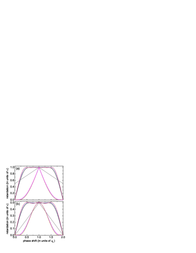
We first discuss the behavior of the broadband sequences (indicated by black solid, blue dashed, and red dotted lines in each plot). Compared to the single conventional plate, the broadband sequences show much less variation of the retardation around the design phase shift . This becomes very clear in Fig. 2(a) where we depict the deviation from the target retardation for the broadband HWPs.
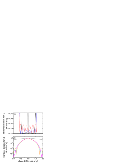
Obviously, the bandwidth of the retarders can be increased by allowing for larger deviations from the target retardation. For example, by allowing a relative deviation of (class III) from a target retardation of instead of (class I), the bandwidth increases from 0.81 (see black solid line in Fig. 1(a)) to 1.17 (see red dotted line in Fig. 1(a)). Such an increase of operation bandwidth at the expense of less accuracy of retardation was shown and discussed for three and five stack sequences in HHJ05 . The feature is in particular important for experimental implementations, which anyway suffer from inevitable losses (e.g., due to non-perfect polarization of light beams or wavelength-dependent reflections). Thus, we can reduce the required number of plates in the composite broadband retarder, while still maintaining a large bandwidth.
We draw now our attention to the behavior of the narrowband sequences, depicted in Fig. 1 by the magenta solid, dark cyan dashed, and orange dotted lines. In contrast to the broadband sequences, the optical retardation changes here much faster than for a single conventional plate. This allows the setup of filters, which change the polarization only in a narrow spectral range (e.g., such as the Lyot L44 or olc filters S53 ). It also permits matching of polarizations in two collinear beams at different wavelengths, even if they were overlapped by a polarizing beamsplitter before. As for the broadband sequences, the bandwidth can also be adjusted for narrowband operation by allowing certain deviations (now from a retardation of zero) for phase shifts away from (see Fig. 2(b)). Similar dependencies also show up for QWPs.
We note, that the phase shift relates to the wavelength via , where is the wavelength-dependent difference in the refractive index for the ordinary and extraordinary waves. For operation at ultra-broad spectral bandwidth, we must consider the dependence for realistic predictions (see Sec. IV).
To the best of our knowledge, our sequences for composite broadband and narrowband retarders made of identical individual plates are the most efficient sequences (in terms of bandwidth) discussed in the literature so far. In all previous works, we find only one composite achromatic QWP for the THz range which shows a similar performance (for a higher number of free parameters)MG06 . However, this particular composite QWP is made of non-standard retarders (i.e., with ) and therefore is rather difficult to implement experimentally in the optical region.
III Experiment
We performed experiments to verify our predictions for the composite optical retarders. In these measurements we used up to 5 individual commercially available zero-order waveplates (Casix, WPZ1225-L/2-780 and WPZ1225-L/4-780, 1 inch diameter). These waveplates were designed and anti-reflection (AR) coated for a center wavelength of 780 nm. We determined the optical axes of the plates with an accuracy of . Manual rotation mounts held each plate, which allowed us to adjust the relative angles of the optical axis and tilt the plates with respect to each other. Tilting the plates by a few degrees turned out to be necessary due to the small AR coating bandwidth as compared to the ultra-broad retardation bandwidths of the composite sequences. Otherwise, outside the bandwidth of the AR coating, reflections at the interfaces would lead to numerous reflexes which would prevent a measurement of the conversion efficiency without separating the reflexes from the main beam. Also, the resulting interference would be detrimental to the performance of the retarders C04c . We note that tilting the plates leads to a shift of the central wavelength. For small angles (as in our experiments) this shift is negligible.
We applied several distinct light sources (i.e., lasers) to demonstrate the ultra-broad and narrow bandwidths of the composite sequences. Standard laser diodes provided radiation at 405 nm, 532 nm, 780 nm, and 850 nm. A Helium-Neon laser served as a light source at 633 nm. A fiber laser-pumped (IPG Photonics Model YAR-15K-1064-LP-SF) optical parametric oscillator (Lockheed Martin Aculight Argos Model 2400) provided radiation at 1550 nm (signal) and at 1064 nm (pump).
For an exemplary experimental demonstration of the composite sequences we restricted ourselves mainly to symmetric sequences with an effective number of plates for the HWPs and plates for the QWPs. Apart from this, we also tested the asymmetric BB1 sequence W94 , previously proposed by Ardavan A07b . The tests worked as follows (see also Fig. 3):
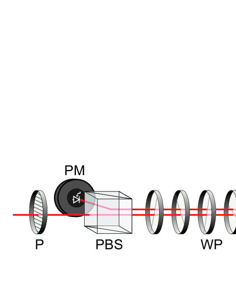
We guided the radiation from the various lasers to the test setup by optical fibers. We collimated the radiation by an adjustable collimation lens to a diameter of about 3 mm (FWHM). We polarized the light in the horizontal () direction with a polarizer (P). Afterwards the light propagated over a distance of 3 meters, and was reflected back by a mirror (M) close to normal incidence. The angle separation between incoming and outgoing beam was less than 0.2∘. The composite waveplate sequences under investigation were placed right in front of the mirror. After propagating back by another 3 meters through the waveplate sequences, we guided the light onto a polarizing beam splitter (PBS) cube for polarization analysis. We applied appropriate AR-coated PBSs matched to each wavelength applied in the tests. We measured the transmitted and/or reflected power after the PBS with a suitable powermeter (PM).
The symmetric arrangement of rotation angles in the composite sequences with respect to the center waveplate (compare Table 1, with the exception of the BB1 sequence for comparison) permitted us to implement a simple double-pass setup with back-reflection. Thus, we replaced a setup intended for individual HWPs by 3 HWPs [H], 1 QWP [Q] and a retro-reflecting mirror [M], in order [HHHQM] (from left to right, compare Fig. 3). This yields a much more compact setup and less optical elements are required. Only the BB1 sequence (with an asymmetric arrangement of angles) consisting of 5 HWPs was tested with a single-pass geometry.
We then aligned the waveplates such as to produce a rotation of the polarization by 90∘, i.e., from to polarization. For the tests of the QWP sequences, we passed the light twice through the complete sequences (in order [QHHQM]), hence using them as HWPs. Also in this case, the waveplates were adjusted such as to produce a rotation of the polarization from to . This simplified the measurements as only the transmitted or reflected power after the PBS had to be measured.
To align the rotation of the individual plates, we proceeded as follows: We started by setting the angles according to the calculated values within an accuracy of . Next, we tilted the plates such that reflexes produced by the waveplates (e.g., at 532 nm, outside the bandwidth of the AR coating) did not coincide with the original beam to perturb our power measurement. As the conversion efficiency from to polarized light should reach a maximum at the center wavelength of 780 nm, we then measured the transmitted power at this wavelength behind the PBS ( polarization). Afterwards, we adjusted the optical axis of each plate iteratively within approximately to minimize the transmission. With such alignment of the sequences, we then measured the conversion efficiencies from to polarization for all available wavelengths. The conversion efficiency was measured asthe ratio of reflected power after the PBS compared to the incident power before the PBS. In addition, we also considered transmission and reflection losses at the PBS.
IV Results & Discussion
IV.1 Ultra-broadband Retarders
Figure 4(a) shows the experimental data (symbols) of the conversion efficiency from to polarization for several composite broadband half-wave retarders in a broad wavelength range. The rotation angles of the optical axes of the single plates and their configuration for the various sequences are given in Table 2. These angles differ from the ones in Table 1. We chose sequences with lower degree of retardation purity for the experimental demonstration in order to observe clear differences between them within our experimental precision. We therefore chose to present sequences with smaller, respectively, larger relative retardation variations , in order to demonstrate the functionality of our numerical optimization method which allows for arbitrary retardation specifications. For each set of data in Fig. 4 we also show the theoretical prediction (solid lines) for the composite retarders based on the Jones calculus. Here, we also took the wavelength dependence G99 of the birefringence in the single quartz wave plates into account. The calculated conversion efficiency of the composite retarders from horizontal () to vertical () linear polarization is defined as follows : For a composite HWP we define , while for a composite QWP we define . The idea of this definition is, that in our experiment we test QWPs as HWPs by passing the light twice through the QWP sequences. Labels 1 and 2 denote the polarization basis vectors. The same symmetry as for relative to (see Sec. II) holds for the conversion efficiency profiles (for quarter-wave retarders is required).
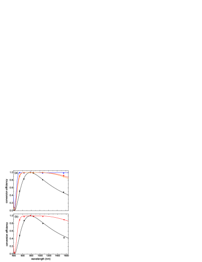
For comparison of our new composite sequences, we also show the measured conversion efficiency of a conventional single HWP (black data, squares) as well as the BB1 sequence proposed by Ardavan A07b (orange data, triangles). The BB1 sequence which is always implemented with individual HWPs already offers a clear improvement compared to the single HWP (black data, squares).
We consider now some of our proposed CP sequences with effective plates, implemented with individual plates. The data set in red rhombs shows the results for a new broadband sequence with a flat plateau. The sequence has a slightly broader bandwidth of 700 nm compared to the BB1 sequence (orange data, triangles). This is partially due to the larger number ofeffective plates. The blue colored data (dots)show the results for a sequence where we allowed a deviation from the target retardation of about 10∘. This results in a to conversion efficiency of better than 0.99 over a huge bandwidth of more than 1100 nm. We note, that the performance of our composite broadband retarders is intrinsically limited by the bandwidth of the AR coatings. To our knowledge, AR bandwidths as large as the this retardation bandwidth are commercially not available. For the calibration of our data we therefore took the reflection losses at the stack of wave plates into account.
| (i) broadband half-wave retarders (see Fig. 4(a)) | ||
| line color | (), [plate sequence] | |
| orange | 0 | (0, 127.8, 23.3, 23.3, 127.8), [HHHHH] (BB1) |
| red | 0 | (0, 106.0, 177.2, 232.4), [HHHQM] |
| blue | (-39.7, -23.3, 10.9, 78.7), [HHHQM] | |
| (ii) broadband quarter-wave retarders (see Fig. 4(b)) | ||
| line color | (), [plate sequence] | |
| red | 0 | (45.0, 96.8, 171.1, 96.8, 45.0), [QHHHQM] |
| (iii) narrowband half-wave retarders (see Fig. 5) | ||
| line color | (), [plate sequence] | |
| magenta | 0 | (26.3, 7.2, 45.5, 14.6), [HHHQM] |
| dark cyan | 0.0025 | (22.5, 34.7, 54.4, 55.8), [HHHQM] |
Let us turn to an example for a novel composite QWP sequence. Figure 4(b) shows experimental data (symbols) along with theoretical predictions (lines). We tested the performance of the QWPs by passing the light beam twice through the arrangement, i.e., using the QWP in double-pass as HWPs. As before, we investigated the performance of polarization rotation from to to define the conversion efficiency. For comparison, we also recorded data for a single conventional zero-order QWP (black squares in Fig. 4(b)). The data for the new broadband composite QWP are shown as red dots in the figure. As for the HWPs, we find good agreement between theoretical prediction and experiment. The composite QWP offers a bandwidth of more than 500 nm where the conversion efficiency is above 0.99, i.e., well beyond that of a conventional zero-order plate.
We note the following issues: (i) We attribute the small deviations of some of the experimental data from the theoretical predictions to the effect of interferences due to multiple reflections at wavelengths outside the window of the AR coatings (see also Clarke C04c ). (ii) In a simple picture, we would expect to find a minimum of the conversion efficiency at half of the design wavelength, hence at 390 nm. According to the calculation, this minimum occurs at an wavelength of about 415 nm. The shift is due to the wavelength dependence of the refractive indices .
IV.2 Narrowband Retarders
Finally, we consider now the data taken for composite narrowband retarders. In the experiment, we applied the new narrowband retarders as highly chromatic HWPs between two crossed polarizers. Due to the symmetry of the rotation angles, we applied again a double-pass configuration. Hence we used plates in order [HHHQM] to implement a composite sequence of effectively plates. This is similar to a folded (type I) olc filter S65 .
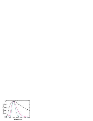
The data sets in magenta stars and dark cyan dots in Fig. 5 show the performances of two narrowband sequences. The broader sequence (magenta) shows almost negligible sidebands at a conversion efficiency deviation below . The narrower sequence exhibits sidebands at a level below . The composite narrowband retarders reduce the bandwidth by a factor of 2-3 compared to a single conventional zero-order HWP (black data, squares). Thus, the filter performance significantly increases. We can get even smaller bandwidths for the narrowband sequences by allowing larger deviations from the desired minimal retardation or by using more individual plates. We note, that the filter depicted by the data set in cyan dots exhibits a slightly larger bandwidth than the corresponding olc filter with 7 plates. However, the sidebands of this composite narrowband retarder are approx. 7 times smaller.
V Summary
We presented new sequences of spectrally ultra-broadband and narrow-band polarization retarders. The concept is based on combination of conventional, identical zero-order waveplates with the optical axis of the single retarders rotated by appropriate angles. We used the mathematical analogy between the description of polarization rotation and the dynamics of a light-driven two-level quantum system (i.e., the concept of composite pulses) to determine optimal rotation sequences of waveplates. In comparison to single waveplates, the novel composite sequences can either reduce the chromatic dependence of the retardation (i.e., to provide operation at ultra-broad bandwidth) or increase the chromatic dependence (i.e., to provide narrow-band retarders in filters). We theoretically determined appropriate sequences of rotation angles for ultra-broadband and narrowband HWPs as well as QWPs. We tested some sequences experimentally and compared their performance to conventional zero-order waveplates as well as (in the case of broadband HWPs) to a sequence known from the field of NMR. Our new composite sequences proved to be superior in all cases. In particular, we demonstrated a composite HWP with a conversion efficiency from to polarized light above 0.99 in a huge spectral range with bandwidth of more than 1100 nm (centered at 780 nm). We also obtained a large increase of operation bandwidth for a novel composite QWP. Moreover, we found and demonstrated new sequences for composite highly-chromatic narrowband HWPs, which enables high-performance applications in filters such as Lyot or olc filters.
VI Acknowledgments
The research leading to these results has received funding from the Deutsche Forschungsgemeinschaft and the European Union Seventh Framework Programme (FP7/2007-2013) under grant agreements n∘ PCIG09-GA-2011-289305 and iQIT and the Bulgarian NSF grant DMU-03/103.
References
- (1) E. Hecht, Optics (4th Edition) (Addison Wesley, 2002).
- (2) D. Grischkowsky, S. r. Keiding, M. van Exter, and C. Fattinger, “Far-infrared time-domain spectroscopy with terahertz beams of dielectrics and semiconductors,” Journal of the Optical Society of America B 7, 2006–2015 (1990).
- (3) J.-B. Masson and G. Gallot, “Terahertz achromatic quarter-wave plate,” Optics Letters 31, 265–267 (2006).
- (4) S. Hanany, J. Hubmayr, B. R. Johnson, T. Matsumura, P. Oxley, and M. Thibodeau, “Millimeter-wave achromatic half-wave plate,” Applied Optics 44, 4666–4670 (2005).
- (5) G. Pisano, G. Savini, P. A. R. Ade, V. Haynes, and W. K. Gear, “Achromatic half-wave plate for submillimeter instruments in cosmic microwave background astronomy: experimental characterization,” Applied Optics 45, 6982–6989 (2006).
- (6) T. Matsumura, S. Hanany, P. A. R. Ade, B. R. Johnson, T. J. Jones, P. Jonnalagadda, and G. Savini, “Performance of three- and five-stack achromatic half-wave plates at millimeter wavelengths,” Applied Optics 48, 3614–3625 (2009).
- (7) Z. Zhuang, Y. J. Kim, and J. S. Patel, “Achromatic linear polarization rotator using twisted nematic liquid crystals,” Applied Physics Letters 76, 3995–3997 (2000).
- (8) M. D. Lavrentovich, T. A. Sergan, and J. R. Kelly, “Switchable broadband achromatic half-wave plate with nematic liquid crystals,” Optics Letters 29, 1411–1413 (2004).
- (9) D. Clarke, “Achromatic Halfwave Plates and Linear Poliarization Rotators,” Optica Acta: International Journal of Optics 14, 343–350 (1967).
- (10) J. M. Beckers, “Achromatic Linear Retarders,” Applied Optics 10, 973–975 (1971).
- (11) J. M. Beckers, “Achromatic Linear Retarders with Increased Angular Aperture,” Applied Optics 11, 681–682 (1972).
- (12) S. Pancharatnam, “Achromatic Combinations Of Birefringent Plates Part II: An achromatic quarter-wave plate,” The Proceedings of the Indian Academy of Sciences XLI, 137–144 (1955).
- (13) C. J. Koester, “Achromatic Combinations of Half-Wave Plates,” Journal of the Optical Society of America 49, 405–407 (1959).
- (14) A. M. Title, “Improvement of Birefringent Filters. 2: Achromatic Waveplates,” Applied Optics 14, 229–237 (1975).
- (15) C. M. McIntyre and S. E. Harris, “Achromatic Wave Plates for the Visible Spectrum,” Journal of the Optical Society of America 58, 1575–1580 (1968).
- (16) A. Ardavan, “Exploiting the Poincaré-Bloch symmetry to design high-fidelity broadband composite linear retarders,” New Journal of Physics 9, 24 (2007).
- (17) S. Wimperis, “Broadband, Narrowband, and Passband Composite Pulses for Use in Advanced NMR Experiments,” Journal of Magnetic Resonance, Series A 109, 221–231 (1994).
- (18) H. Cummins, G. Llewellyn, and J. Jones, “Tackling systematic errors in quantum logic gates with composite rotations,” Physical Review A 67, 042308 (2003).
- (19) M. H. Levitt, “Composite pulses,” Progress in Nuclear Magnetic Resonance Spectroscopy 18, 61–122 (1986).
- (20) S. S. Ivanov, A. A. Rangelov, N. V. Vitanov, T. Peters, and T. Halfmann, “Highly efficient broadband conversion of light polarization by composite retarders,” Journal of the Optical Society of America A 29, 265–269 (2012).
- (21) B. Lyot, “Filter monochromatique polarisant et ses applications en physique solaire,” Ann. Astrophys. (Paris) 7, 32–79 (1944).
- (22) I. Šolc, Česk. Časopis Fys. 3, 366 (1953).
- (23) J. M. Beckers, L. Dickson, and R. S. Joyce, “Observing the sun with a fully tunable Lyot-Ohman filter,” Applied Optics 14, 2061–2066 (1975).
- (24) G. A. Kopp, M. J. Derks, D. F. Elmore, D. M. Hassler, J. C. Woods, J. L. Streete, and J. G. Blankner, “Tunable liquid-crystal filter for solar imaging at the He i 1083-nm line,” Applied Optics 36, 291–296 (1997).
- (25) J. W. Evans, “Solc Birefringent Filter,” Journal of the Optical Society of America 48, 142–143 (1958).
- (26) I. Šolc, “Birefringent Chain Filters,” Journal of the Optical Society of America 55, 621–625 (1965).
- (27) A. J. Shaka, “Composite pulses for ultra-broadband spin inversion,” Chemical Physics Letters 120, 201–205 (1985).
- (28) D. Clarke, “Interference effects in Pancharatnam wave plates,” Journal of Optics A: Pure and Applied Optics 6, 1047–1051 (2004).
- (29) R. C. Jones, “A New Calculus for the Treatment of Optical Systems,” Journal of the Optical Society of America 31, 488–493 (1941).
- (30) G. Ghosh, “Dispersion-equation coefficients for the refractive index and birefringence of calcite and quartz crystals,” Optics Communications 163, 95–102 (1999).