Degrees-of-Freedom Region of Time Correlated MISO Broadcast Channel with Perfect Delayed CSIT and Asymmetric Partial Current CSIT
Abstract
The impact of imperfect CSIT on the degrees of freedom (DoF) of a time correlated MISO Broadcast Channel has drawn a lot of attention recently. Maddah-Ali and Tse have shown that the completely stale CSIT still benefit the DoF. In very recent works, Yang et al. have extended the results by integrating the partial current CSIT for a two-user MISO broadcast channel. However, those researches so far focused on a symmetric case. In this contribution, we investigate a more general case where the transmitter has knowledge of current CSI of both users with unequal qualities. The essential ingredient in our work lies in the way to multicast the overheard interference to boost the DoF. The optimal DoF region is simply proved and its achievability is shown using a novel transmission scheme assuming an infinite number of channel uses.
I Introduction
Maddah-Ali and Tse have recently investigated the DoF region of Broadcast Channels with perfect delayed (completely stale) CSIT [1]. They have shown that the per-user optimal DoF is in a two-user setup and proposed a simple transmission scheme (denoted as MAT scheme in the sequel) to achieve that DoF over 3 time slots. In the first and second slot, each user in turn receives the desired signal and overhears the unwanted signal, while in the third slot, the sum of the overheard interference is transmitted to enable the decoding of the desired signal at each receiver.
Those results have recently been extended to a more general setup with perfect delayed CSIT and partial current CSIT [2] [3]. An optimal combining of perfect delayed CSIT and partial current CSIT is obtained to bridge the DoF of [1] with outdated CSIT and the DoF achievable with zero-forcing beamforming with perfect current CSIT. However results in [2] and [3] are limited to a symmetric case where the transmitter has access to both users’ CSI with the same accuracy.
In [4], an outer-bound on the DoF region was given under the settings that the transmitter and receivers have multiple antennas and perfect delayed CSIT. The authors of [5] and [6] studied the same settings but without CSIT. Moreover, In [7][8], the optimal sum DoF of was derived when the CSIT of one user is perfect but it is out-dated for the other user.
In this paper, we further extend the analysis by considering a more general asymmetric scenario where the qualities of current CSI of users’ channels available at the transmitter are unequal. Our contributions are summarized as follows:
-
1.
the transmission schemes derived for the symmetric case are shown to incur a DoF loss in an asymmetric scenario,
-
2.
the DoF region obtained in [2] is extended to the asymmetric scenario and is expressed as a function of two parameters representing the accuracy of CSIT of each user’s channel,
-
3.
a novel transmission scheme (that subsumes the scheme in [2] in the symmetric case) is derived and shown to achieve the DoF region in the limit of an infinite number of channel uses.
At the time of submission, we have been informed of another independent work, also in submission, that addresses the same problem [9]. Interestingly, both works derive the same achievable DoF region using different approaches and its achievability is demonstrated using two different transmission strategies.
The rest of this paper is organized as follows. The system model is introduced in Section II and the DoF region is derived in Section III. The limitations of the transmission schemes designed for symmetric partial current CSIT are discussed in Section IV and a novel transmission scheme achieving the optimal DoF region in the setting of asymmetric partial current CSIT is introduced. Section V concludes the paper.
The following notations are used throughout the paper. Upper letters in bold font represent matrices whereas bold lower letters stand for vectors. However, symbol not in bold font represents a scalar. and represent the transpose and conjugate transpose of a matrix or vector respectively. denotes the orthogonal space of channel vector . refers to the expectation of a random variable, vector or matrix. is the norm of a vector. corresponds to , where refers to SNR throughout the paper and logarithms are in base .
II System Model
We consider a two-user Broadcast Channel with two transmit antennas and one antenna per user. and are the channel states at time slot of user 1 and user 2 respectively. Denoting the transmit signal vector as , subject to a transmit power constraint , the observations at receiver 1 and 2, and respectively, can be written at time slot as
| (1) | ||||
| (2) |
where and are unit power AWGN noise. Signal vector is expressed as a function of the symbol vectors for user 1 and user 2, denoted as and respectively. is a two-element symbol vector containing and . is defined similarly and is composed of and . The power allocated to symbol is stated as while the rate achieved by is . As , the power and rate of are expressed as and . These notations are applicable to , and . For the sake of convenience, in a few instances, we denote the rate of each symbol or symbol vector by the pre-log factor (ignoring ).
The channel state information and are supposed to be mutually independent and identically distributed with zero mean and unit covariance matrix ( and ). At any given time slot , the transmitter and each user have perfect global knowledge of the channel states from time slot to , i.e. and . Moreover, the transmitter can predict the current channel state of each user. The estimated channels are denoted as and , with the corresponding error vectors written as and . and have the variances denoted as and , respectively. In the general asymmetric scenario under interest, the transmitter has unequal accuracy of the current CSI for each user, with the accuracy of the each current CSIT obtained according to
| (3) |
In other words, and . and are supposed to vary in the range of , where represents no CSIT whereas stands for perfect CSIT. Throughout the paper, we assume without loss of generality. Moreover, it is important to note the relationship and .
III DoF Region with Asymmetric Partial Current CSIT
Theorem 1
In the two-user MISO Broadcast Channel with perfect delayed CSIT and asymmetric partial current CSIT, the optimal DoF region is characterized by
| (4) |
A sketch of the proof will be given in the Appendix. The DoF region is illustrated in Figure 1. As shown, the outer-bound is a polygon composed of the points , and . When is fixed, the intersection point which maximizes the sum DoF moves as increases. However, the intersection point goes outside the valid region as shown by the circle point in Figure 1 when . In this case, the region is only formed by , . Also, the point that achieves the maximum sum DoF returns to the triangle point (see Figure 1) achieved by taking . When , the DoF region boils down to that of [2] as shown by the diamond point, suggesting that scheme II in [2] achieves a subset of the asymmetric region. Moreover, when , the region further boils down to the region achieved by MAT scheme in [1].
center 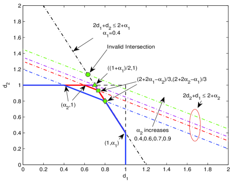
IV Achievability
IV-A Limitation of scheme II in [2]
Following the system model defined in Section II, we briefly review the transmission scheme II as proposed in [2] and identify the limitations of that scheme in an asymmetric configuration. The transmit signal and the received signal at each user at first time slot write as
| (5) | ||||
| (6) | ||||
| (7) |
where and , . (resp. ) represents the overheard interference generated at receiver 1 (resp. 2) at slot 1 and is expressed as
| (8) | ||||
| (9) |
By integrating the current CSIT in the precoding procedure to , and are received with the power of and respectively since and have the respective quality of and . As both overheard interferences have reduced power, the resource can be saved when multicasting them separately and sequentially at slot 2 and 3. The transmission and receive signals at slot 2 and 3 are expressed as
| (10) | ||||
| (11) | ||||
| (12) |
| (13) | ||||
| (14) | ||||
| (15) |
where, and are quantized versions of overheard interference with the quantization rate of and respectively. and are new symbols at slot 2 intended to user 1 and user 2 respectively. Similarly, and are defined at slot 3. The power allocated to each symbols in (10) and (13) are , and .
At each receiver, and are decoded at the first stage of SIC by treating all the other symbols as noise. At high SNR, and can be decoded at both receiver with the same rate as their respective quantization rate. Then (resp. ) can be employed to cancel the overheard interference (resp. ) and provide another independent observation to (resp. ). Consequently, and achieve the rate of and , respectively. At slot 2, (resp. ) is drown by the noise in (resp. ) so that user 1 (resp. user 2) can decode (resp. ) without interference, thus, . At slot 3, the limitation rises because is overheard by user 1 with the power of , which is larger than the noise level. Then, is decoded by treating as noise so that the rate of is restricted to while . To sum up, the DoF of each user’s symbols is . However, this DoF satisfies (4) and lies within the DoF region. It is outperformed by the intersection point and user 2 incurs a DoF loss of . The loss vanishes in the symmetric case as , where the above scheme achieves the optimal bound [2].
To boost up the DoF achieved at slot 3, the overheard interference can be removed via retransmission at slot 4. However, since is decodable by user 2 at slot 3, this retransmission is wasteful for user 2. To make the retransmission efficient for both users, we compose of and as a symbol vector rather than a single symbol. is precoded and allocated with the power same as that of , is transmitted with power so that the power of is not enhanced compared to . After receiving and decoding the quantized overheard interference, user 1 can remove while user 2 can decode both and .
Accordingly, as long as one user overhears interference, the retransmission of the overheard interference is efficient in improving the DoF if we make the overheard interference composed of two symbols. Based on this observation, we derive a novel transmission scheme in the next section.
IV-B Building Blocks of a New Transmission Scheme
We identify important building blocks of a new transmission scheme that achieves the asymmetric DoF region of Theorem 1. Building upon scheme II in [2], a more general transmission at a given time slot writes as
| (16) |
where can be made up of multiple overheard interferences generated at any previous slots . The power and rate allocated to each symbol are defined for a given quantity as shown in Table I that represents a fraction of channel use and whose physical meaning will appear clearer in the sequel.
center Symbols Power Encoding Rate
Regarding and the power allocated to each symbol, the received signal at each user can be written as
| (17) | ||||
| (18) |
where and are overheard interferences received with the power and , respectively. Both and are composed of two symbols as
| (19) | ||||
| (20) |
To save the resource required by retransmission, and are quantized at the end of slot as
| (21) |
where, and are the quantized overheard interference, and are the quantization errors. According to the Rate-distortion theory [10], we quantize and using and bits, which are equal to and respectively, allowing the quantization noise to have the same variances as AWGN. As a result, and can be employed to remove the overheard interference completely while providing an additional observation to enable the decoding of all symbols.
Moreover, , decoded with rate by treating all the other components as noise at both receivers, can be considered as occupying channel use, leaving channel use for the new symbols, and . The number of new symbols transmitted highly depends on the value of . If , both users will observe an overheard interference. When , only is sent to user 1 and will be drown by the noise in , thus, only one overheard interference () needs to be retransmitted. However, when , only and are transmitted and they will be drown by the noise in and respectively so that the transmission can finalize without the requirement of overheard interference retransmission.
Looking at the aforementioned transmission model, all the new symbols are not decodable until the transmissions of overheard interferences are completed. As a consequence, we consider all the channel uses employed to decode all the new symbols as a ”virtual channel”, which normally consists of two parts: the first part is the transmission of new symbols, the second part refers to the retransmission of overheard interferences, which can boost the DoF from two aspects: 1) help user remove overheard interference; 2) provide an additional independent observation to enable decoding.
Next, as the limitation of the scheme in [2] lies at time slot 3, we derive the achievable scheme maintaining the transmission in the first two time slots plus the transmission of at time slot 3. Over those channel uses, the DoF achieved by each user is .
Moreover, as illustrated in Figure 1, the DoF region varies depending on the location of the intersection point. Obviously, when , the intersection point lies on or outside the valid region formed by and . The maximum sum DoF is obtained by the point . When , the intersection point is located inside the valid region and achieves the maximum sum DoF. Hence, the achievable schemes are sketched in these two cases respectively.
IV-C Case I: -Achieving
Lemma 1: Assume the perfect delayed CSIT and partial current CSIT with and for each user. Under the condition (), the achievable DoF is .
Proof: In addition to the existing two time slots of scheme II in [2] shown as (5) and (10), at time slot 3, the transmission is processed according to the scheme described in section IV-B, which is expressed in the following group of equations as
| (22) | ||||
| (23) | ||||
| (24) |
with the power and rate allocation given in Table II, where .
center Symbols Power Encoding Rate
The power of and are not shown because , and . As in (23) and (24), the transmission signal have the same form, the received signal at each user can be written in general as
| (25) | ||||
| (26) |
where is given as (19) and quantized as via (21). Regarding the transmission flow and power allocation, two virtual channels can be established from slot 3 to 5.
IV-C1 Virtual Channel 1
This virtual channel contains the transmission of , plus . At slot 3, channel use remains after transmitting , so that one symbol, , is intended to user 1 and two symbols, and to user 2. The interference overheard by user 1, , has power , while user 2 overhears nothing since is drown by the noise. At the end of slot 3, is quantized as with rate and sent using channel use at slot 4.
IV-C2 Virtual Channel 2
This virtual channels consists of the transmission of and together with . At slot 4, channel remains for and after transmitting . Under the condition that , the transmitter will send only one symbol, to user 1 but two symbols, and to user 2. Consequently, is the only overheard interference at slot 4 with power . In each virtual channel, three new symbols and one overheard interference are transmitted. The only difference between these two virtual channels lies in the power allocation. The decodability is sketched next.
Firstly, as aforementioned, the overheard interference must be decoded first to enable the decoding procedure for the new symbols. From and , is decoded by treating all the other symbols as noise. To be specific, at observation , the rate of is , while it is from . As shown in Table II, we let , is decoded with the same rate at both receivers. Moreover, as is seen by user 1 with power of in (25), can completely recover provided that .
Secondly, is employed to remove the overheard interference in (25) and provide an additional independent observation for user 2. Denoting and as the signal after decoding and subtracting from and respectively, we write the decoding of and as
| (27) | ||||
| (34) |
where , and have unit power so that is decodable with the rate of and achieves the rate of .
Replacing the power stated in Table II, the first virtual channel lasts for channel uses, over which the rates achieved are and . Similarly, they are and during the channel uses in virtual channel 2. In all, when we consider these two virtual channels which last for 2 channel uses, the DoF is
| (35) |
Moreover, when the transmission continues, the amount of remaining channel uses at slot 5 is , which is identical to slot 3. Repeating the same transmission results in overheard by user 1 with the rate , leading to and at slot 6. In this way, the transmission can keep cycling with the same strategy as at slot 3 and 4. Combining with the transmissions prior and and assume the strategy is repeated for times, the asymmetric DoF is given by
| (36) | |||||
IV-D Case II: -Achieving
Lemma 2: Assume the transmitter has perfect delayed CSIT and partial current CSIT with and for each user. Under the condition (), the achievable DoF is .
Proof: To close the gap mentioned in section IV-A, we derive the achievable scheme from slot 3 (The first two slots are the same as in Case I). The transmission flow is expressed in the following group of equations as
| (37) | ||||
| (38) | ||||
| (39) | ||||
| (40) |
where, and , given in (19) and (20), are quantized with rate and respectively at the end of each slot via (21). Since the transmission and power allocation at slot 3 and 5 are identical to that in Table II, Table III only provides the power and the encoding rate at slot 4 and 6.
center Symbols Power Encoding Rate
Regarding the transmission flow and power allocation, three virtual channels are constructed from slot 3 to 6.
IV-D1 Virtual Channel 1
This virtual channel consists of the transmission of , and . Power of and are stated in Table II. results in , which is quantized as . The sending of occupies channel uses at slot 4. This virtual channel is identical to the first virtual channel in case I (see Section IV-C). The decodability can be derived in the same way as (25) and (26). The total amount of channel uses is , over which the rates achieved by the symbols for each user are and .
IV-D2 Virtual Channel 2
This virtual channel is made up of and and the retransmission of and . At slot 4, the remaining amount of channel use for new symbols is , which is higher than so that the transmitter sends two symbols per user, resulting in the overheard interference and generated at user 1 and user 2 respectively. The observations at each receiver are written as
| (41) | ||||
| (42) |
At the end of slot 4, and are obtained via quantization with rates and respectively, whose pre-log factors are and . The decodability of the new symbols in this virtual channel is enabled after decoding and , which are transmitted using part of the channel at slot 4 and 5 respectively. The received signals of user 1 at slot 5 and 6 are expressed as
| (43) | ||||
| (44) |
By treating all the other symbols as noise, is obtained with the rate of . Revisiting Table II, so that is decodable with rate and can be successfully recovered. Similarly, is decoded from by treating all the other symbols as noise, among which, is the dominant component. Consequently, is decoded with the rate of , which meets its distortion rate . Similarly, and are decoded from and respectively. Denoting and , the decoding formulas for and are
| (51) | ||||
| (58) |
where , , and have unit power, and can be decoded with the rate of and , respectively, which equal their encoding rate. As a result, virtual channel 2 lasts for channel uses while the rate achieved are and .
IV-D3 Virtual Channel 3
This virtual channel contains the transmissions of , and . As the transmission and power allocation of and are identical to that at slot 3, is quantized with the rate . After subtracting from (44), is decoded by treating the rest as noise, among which, is the dominant. The decoding rate of is , whose pre-log factor is . Consequently, can be employed to remove the interference in and provide an additional observation to . In this way, and can be decoded using (25) and (26). The rates achieved are and over the channel use.
In all, looking at those three virtual channels which last for 3 channel uses in total, the DoF achieved are expressed as
| (59) |
Combining with the DoF prior to and and cycling those three virtual channels for times, the achievable DoF is
| (60) |
IV-E Case II: -Achieving
Point is achieved under the condition that as in case I but by reusing the flow described in Section IV-C. The first virtual channel is maintained, where and achieve the rate of and respectively and consume channel uses. However, the second virtual channel is changed by reallocating the power of from to . In this way, the amount of channel uses in this virtual channel is kept to , while the rates achieved become and . As a result, the DoF achieved using this 2 channel uses are .
IV-F Achieving
Point is achieved in a ”SC+ZF” manner which has been mentioned in [2]. The transmission scheme is finished in one slot and is expressed as
| (61) |
where is intended to user 1 and transmitted with power superposed to and , which are transmitted with power . and are precoded to the orthogonal space of the channel of their unintended user. At each receiver, is decoded with the rate of using SIC. After subtracting , user 1 decodes with the rate of without any interference. Similarly, user 2 obtains with DoF of . Resultantly, point is achieved.
As a last remark, we note the similarity of this work with [9], where the same DoF region is derived under the same system settings. Their achievable scheme in terminated in three phases. The overheard interferences generated in current phase are accumulated and then split evenly across the transmission in the next phase. The optimal bound is achieved by choosing phase durations which optimally combine the transmission of overheard interference and new symbols. However, in this contribution, we achieved the optimal bound by keeping retransmitting overheard interference to boost up the DoF and making every channel use employed efficiently.
V Conclusion
Appendix-Brief Proof of Outer-Bound
The converse proposed in [2] can be reused to prove the optimal region given in Theorem 1. In that work, genie-aided model is employed to construct a physically-degraded channel. Skipping the same fundamental steps, the only difference lies in deriving the following lower bound
| (62) |
are eigenvalues of . are eigenvalues of , is Gaussian distributed as . Replacing (62) into its corresponding equations in [2], we have (63). When switching the role of the two users, (64) is obtained.
| (63) | ||||
| (64) |
References
- [1] M. Maddah-Ali and D. Tse, “Completely stale transmitter channel state information is still very useful,” IEEE Trans. Inf. Theory, vol. 58, no. 7, pp. 4418–4431, 2012.
- [2] S. Yang, M. Kobayashi, D. Gesbert, and X. Yi, “Degrees of freedom of time correlated miso broadcast channel with delayed csit,” IEEE Trans. Inf. Theory, no. 99, p. 14, 2012.
- [3] T. Gou and S. Jafar, “Optimal use of current and outdated channel state information: Degrees of freedom of the miso bc with mixed csit,” Comms Letters, IEEE, vol. 16, no. 7, pp. 1084 –1087, july 2012.
- [4] C. Vaze and M. Varanasi, “The degrees of freedom region of the two-user mimo broadcast channel with delayed csit,” in Proc. IEEE Int. Symp. Inf. Theory (ISIT), 31 2011-aug. 5 2011, pp. 199 –203.
- [5] ——, “The degree-of-freedom regions of mimo broadcast, interference, and cognitive radio channels with no csit,” IEEE Trans. Inf. Theory,, vol. 58, no. 8, pp. 5354 –5374, aug. 2012.
- [6] C. Huang, S. Jafar, S. Shamai, and S. Vishwanath, “On degrees of freedom region of mimo networks without channel state information at transmitters,” IEEE Trans. Inf. Theory, vol. 58, no. 2, pp. 849 –857, feb. 2012.
- [7] H. Maleki, S. Jafar, and S. Shamai, “Retrospective interference alignment over interference networks,” IEEE Journal of Selected Topics in Signal Processing, vol. 6, no. 3, pp. 228 –240, june 2012.
- [8] R. Tandon, M. Maddah-Ali, A. Tulino, H. Poor, and S. Shamai, “On fading broadcast channels with partial channel state information at the transmitter,” in 9th Int. Symp. on Wireless Communication Systems, Paris, France, Aug. 2012.
- [9] J. Chen and P. Elia, “Degrees-of-freedom region of the miso broadcast channel with general mixed-csit,” vol. arxiv/1205.3474, May, 2012.
- [10] T. M. Cover and J. A. Thomas, ”Elements of Information Theory, second edition. New York: Wiley-Intersicence, 2006.