Simultaneous Information and Power Transfer for Broadband Wireless Systems
Abstract
Far-field microwave power transfer (MPT) will free wireless sensors and other mobile devices from the constraints imposed by finite battery capacities. Integrating MPT with wireless communications to support simultaneous wireless information and power transfer (SWIPT) allows the same spectrum to be used for dual purposes without compromising the quality of service. A novel approach is presented in this paper for realizing SWIPT in a broadband system where orthogonal frequency division multiplexing and transmit beamforming are deployed to create a set of parallel sub-channels for SWIPT, which simplifies resource allocation. Based on a proposed reconfigurable mobile architecture, different system configurations are considered by combining single-user/multi-user systems, downlink/uplink information transfer, and variable/fixed coding rates. Optimizing the power control for these configurations results in a new class of multi-user power-control problems featuring the circuit-power constraints, specifying that the transferred power must be sufficiently large to support the operation of the receiver circuitry. Solving these problems gives a set of power-control algorithms that exploit channel diversity in frequency for simultaneously enhancing the throughput and the MPT efficiency. For the system configurations with variable coding rates, the algorithms are variants of water-filling that account for the circuit-power constraints. The optimal algorithms for those configurations with fixed coding rates are shown to sequentially allocate mobiles their required power for decoding in ascending order until the entire budgeted power is spent. The required power for a mobile is derived as simple functions of the minimum signal-to-noise ratio for correct decoding, the circuit power and sub-channel gains.
Index Terms:
Power transmission, cellular networks, power control, energy harvesting, mobile communication.I Introduction
Microwave power transfer (MPT) refers to wirelessly transmitting energy from one place to another. Simultaneous wireless information and power transfer (SWIPT) refers to using the same emitted electromagnetic (EM) wavefield to transport both energy that is harvested at the receiver, and information that is decoded by the receiver.
In the past decades, much research effort has been directed towards developing MPT for replacing cables in long-distance power transfer either terrestrially [1] or from solar satellites to the earth [2]. This has led to a series of breakthroughs in microwave technology including high-power microwave generators and, more importantly in the current context, the invention of rectennas (rectifying antennas) for efficient RF-to-DC conversion [1]. This technology has been applied to the design of helicopters and airplanes powered solely by microwaves [3]. Most prior research on MPT focuses on the design of compact and efficient rectennas or similar energy harvesters [1, 4]. More recently there has been interest in the powering of low-power devices and even trickle-recharging of certain personal communications devices. There is already equipment available that does this [5], by broadcasting omni-directionally with an RF power of about W, and harvesting several mW. With a massive transmitter array, power could be focused so that the harvested power is increased hundreds of times. The power levels involved are still small, much smaller than the emitted RF power by some cell phones (up to 2 W for GSM), so absorption by the human body does not appear to be a fundamental technological problem. Moreover, various safety precautions could be applied if deemed important.
With SWIPT, one and the same wave-field is used to transmit energy and information. This has several advantages. First, separate transmission of power and information by time division is suboptimal in terms of efficiently using the available power and bandwidth. SWIPT, by contrast, may exploit integrated transceiver designs. Second, with SWIPT, interference to the communication systems can be kept under control. This is especially important in multi-user systems with many potential receivers who would suffer from interference. By contrast, traditional microwave power transfer (MPT) relies on transmission of a single tone (and its unintended harmonics), which can interfere with communication links. Furthermore, MPT does not have any dedicated spectrum. Hence, as such, for use in existing bands, it must be integrated with communication solutions.
A key application of SWIPT that we foresee is to provide power to, and communicate with, sensors for which battery replacement is difficult or even impossible [6]. Radio-frequency identification (RFID) tags are one important example. RFID is already a very widely used technology, but its full potential is probably not fully exploited. A major limitation is the small range of RFID readers with constrained power. Another limitation is the ability of readers to correctly resolve different RFID tag returns that arrive at the receiver superimposed on one another. Many other applications, for example, in the chemical process industry, in environmental monitoring, in oil platforms and pipelines and in surveillance and national security applications require sensors with extreme reliability. Often these sensors transmit rather modest amounts of data, in some applications, only a few bits per hour. Typically the sensors are hard to access and therefore their batteries require long lifetimes and very low failure rates.
Making SWIPT work will require integration between multiantenna transmission, efficient energy harvesting, resource management and signal processing. In particular, theory and methods for massive MIMO [7] may become fundamental enablers for SWIPT. Enabling technology for realizing SWIPT in practice is the theme of this paper.
I-A Prior Related Work
The concept of SWIPT, in a very basic form, has existed for a long time in applications like RFID and power-line communications. It was first studied from an information-theoretic perspective in [8] for a narrow-band noisy channel, and later in [9] for a frequency-selective channel. These papers characterized the fundamental trade-off between communication capacity and power harvested at the receiver. A similar trade-off was derived for a multi-user system in [10]. From a communication theoretic point of view, the novel aspect here is the new constraint on the minimum received power representing the fixed circuit power consumption, called the circuit-power constraint, which results in the said fundamental tradeoff.
These aforementioned studies implicitly assumed that the received energy can be still harvested after passing through an information decoder, which is infeasible given the current state-of-the-art of electronic circuits. This motivated the design of practical SWIPT-enabled receivers that split the received microwave signal from each antenna and feed it to two separate circuits, one for information decoding and one for energy harvesting [11, 12]. The corresponding capacity-and-energy tradeoffs are characterized for the multiple-input-multiple-output (MIMO) channels with perfect transmitter channel state information (CSIT) [11, 12] and further investigated for the case of imperfect CSIT [13]. An additional scenario considered in [11] is broadcasting from a base station to two receivers taking turns for information decoding and energy harvesting, corresponding to time-division-information-and-power transfer (TD-IPT). This protocol simplifies the receiver design but compromises the efficiencies of MPT and IT since they cannot operate simultaneously. The systems considered in the aforementioned prior works share the common setting that a transmitter draws energy from a reliable source such as the electric grid and then delivers it to passive devices by MPT. A different scenario related to distributive networks such as sensor networks is one where devices exchange energy in addition to peer-to-peer communication. Transmission strategies are proposed in [14] for two devices to exchange information and energy based on TD-IPT over a two-way channel. The principle of energy sharing is also reflected in a relay system studied in [15] where a source node transfers energy to a relay node in return for its assistance in transmission. It is shown that jointly managing the energy queues at these nodes that both harvest energy from external sources can enhance the end-to-end throughput.
Realizing SWIPT in practice requires not only suitable hardware and physical-layer algorithms but also the support of an appropriate network architecture. One such architecture, proposed in [16], overlays a traditional cellular network with additional base stations dedicated for MPT to mobiles. Based on a stochastic-geometry network model and under a quality-of-service constraint for the data links, a tradeoff is derived between the densities of the base stations for MPT and those for IT, giving insight into the optimal network deployment.
A popular modulation method called orthogonal frequency division multiplexing (OFDM) divides a broadband channel into decoupled narrowband sub-channels. OFDM simplifies the channel equalization and multiple access [facilitating orthogonal frequency division multiple access (OFDMA)], which has motivated its adoption in modern communication standards such as 3GPP and WiFi [17]. Designing SWIPT based on OFDM not only retains its existing advantages but also enables simultaneous wireless recharging of multiple devices. The current work represents a first attempt to develop a practical framework for OFDM-based SWIPT that features a practical mobile architecture and a matching set of power-control algorithms that exploit frequency diversity to enhance the efficiency of SWIPT. In parallel with our initial results in [18], an independent study on the same topic was reported in [19]. The practicality of the SWIPT system proposed in [19] seems to be limited in several respects. First, the use of a single-antenna base station for SWIPT leads to isotropic radiation of the transmission power and hence an extremely low MPT efficiency. This is the reason that beamforming is the primary technology for practical MPT solutions [1, 2, 3]. Isotropic MPT also couples the multi-user MPT links and results in difficult power control problems [19]. Second, the design in [19] is based on the assumption that information decoding causes no loss in harvesting the total received energy. While this assumption is common (see, e.g., [8, 9, 10]), we know of no compelling arguments for its practicality. Lastly, a sub-optimal TD-IPT protocol instead of SWIPT is adopted in [19]. These drawbacks of existing approaches may be overcome by the SWIPT framework proposed in this paper.
I-B Summary of Contributions and Organization
This work assumes a noise-limited broadband system where a multi-antenna base station not only communicates with but also wirelessly powers the mobile devices. The broadband channel is partitioned into orthogonal sub-channels by OFDM and the base station transmits/receives one data stream per sub-channel. Streams are encoded with either variable rates adapted to the receive signal-to-noise ratios (SNRs) or fixed rates for which successful decoding requires the receive SNRs to exceed a given threshold. The constraint and threshold are referred to as the minimum-SNR constraint and the SNR threshold, respectively. Assuming sparse scattering and perfect CSIT, the base station steers beams for different sub-channels towards associated mobiles, creating a set of parallel channels for SWIPT. Note that OFDM alone without beamforming can decouple only the IT links but not the MPT links. The transmission power for different sub-channels is controlled subject to a constraint on the total power. We consider both a single-user system where the mobile is assigned all sub-channels and a multi-user system where each mobile is assigned a single sub-channel based on OFDMA. Two practical scenarios for SWIPT are considered depending on if IT is in the downlink or the uplink direction. For SWIPT with downlink IT, the OFDM signal transmitted by the base station is used both for IT and for MPT. For SWIPT with uplink IT, MPT and IT are in the opposite directions where downlink MPT relies on the transmission of unmodulated tones [20], called power tones, and uplink data signals are OFDM modulated. In this scenario, the base station is assumed to support full-duplex SWIPT based on the same principle as proposed in [20]. More specifically, the antenna array at the base station is partitioned into two sub-arrays for transmit beamforming and receive combining and the cross-coupled power tones in the received uplink signal is perfectly canceled. This is viable since the base station has perfect knowledge of the phases and frequencies of the power tones.
A SWIPT-enabled mobile architecture is proposed that can be reconfigured according to the direction of the IT. The architecture consists of dual antennas, one information transceiver and one energy harvester. The harvester continuously converts incoming microwaves to DC power which is used to operate the mobile circuit and to supply transmission power for the uplink IT. This is feasible by using existing energy harvester designs such as those in [12, 16]. When configured for SWIPT with downlink IT, the outputs of the two antennas are combined and then split using a power splitter with an adjustable ratio to yield the inputs of the receiver and harvester, similarly to the designs in [11, 12]. The power splitting ratio provides a degree-of-freedom for managing the received power for IT and MPT. When the architecture is reconfigured for SWIPT with uplink IT, the two antennas are separately attached to the transmitter and harvester and support full-duplex SWIPT in opposite directions. The mobile architecture is assumed to consume fixed circuit power, following practical models [21]. Based on the transmission scheme and mobile architecture described earlier, algorithms for power control at the base station are designed for a comprehensive set of system configurations combining single-user/multi-user systems, downlink/uplink IT, and variable/fixed coding rates. The key features of the proposed algorithms are summarized in Table I.
The remainder of the paper is organized as follows. The system model is described in Section II. The SWIPT-enabled mobile architecture is proposed in Section III. Based on the architecture, power-control algorithms are designed separately for the four scenarios combining single-user/multi-user systems and downlink/uplink IT in Sections IV–VII. Their performance is evaluated by simulation in Section VIII, followed by concluding remarks in Section IX.
| Rate | IT | # of Users | Power-Control Algorithm \bigstrut |
|---|---|---|---|
| Var. | DL | Single or Multiple | The problem of optimal power control is non-convex but can be approximated by the convex formulation of the classic multi-channel power control such that circuit power is accounted for in the constraints. This results in policies that are variants of water-filling. |
| UL | Single | – Downlink power control: The optimal policy is to allocate the maximum power over the strongest sub-channel for maximizing the downlink-MPT efficiency. – Uplink power control: At the mobile, part of the harvested power is used for operating the circuit and the remainder is used to maximize the uplink throughput by water-filling. | |
| Multiple | – Downlink power control: The key design technique is to treat power control as one that injects power into a set of closed-loop sub-channels, where the loss for each sub-channel combines the downlink-and-uplink propagation loss and the circuit-power consumption. Based on this technique, a sub-optimal algorithm is proposed that first schedules active mobiles using the criterion of maximum MPT efficiency and then allocates power by water filling with the water level depending on the circuit power. – Uplink power control: Each mobile spends the maximum available power. | ||
| Fixed | DL | Single or Multiple | Under the the minimum-SNR constraint, the optimal power-control policy is shown to be one that sequentially allocates power to sub-channels in descending order of the corresponding channel gains, which is called greedy channel inversion. |
| UL | Single | – Downlink power control: The optimal policy follows that for the variable-rate counterpart. – Uplink power control: The optimal policy applies greedy channel inversion over the uplink sub-channels. | |
| Multiple | – Downlink power control: The optimal policy performs greedy channel inversion based on the effective gains of the said closed-loop sub-channels, which are derived as closed-form functions of the downlink/uplink sub-channel gains and circuit power. – Uplink power control: Each mobile applies the maximum available power for uplink transmission. |
II System Model
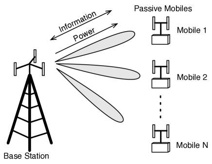
In the single-cell system as illustrated in Fig. 1, a multi-antenna base station communicates with and supplies power to mobiles in a sparse-scattering environment. IT takes place in either the downlink or uplink direction but the MPT is always from the base station to the mobiles. SWIPT uses a wide spectrum partitioned into sub-channels. For a single-user system (), all sub-channels are assigned to a single mobile; for a multi-user system, each mobile is assigned one sub-channel (). Note that the problem formulation for the case of assigning variable numbers of sub-channels to mobiles differs from the current one in having more complex circuit-power constraints, but the solution methods are similar. Ideally, the sub-channel assignments for the multi-user system should be jointly optimized with the power control (see, e.g., [22] for traditional OFDMA systems) but the optimal design for the current scenario seems intractable due to multi-user-circuit-power constraints. For tractability, we assume given sub-channel assignments and focus on the power control. Furthermore, time is slotted and it is assumed for simplicity that the energy storage of all mobiles are empty at the beginning of each slot. Consequently, the instantaneous power harvested by an active mobile is required to meet the circuit-power constraint. Relaxing the said assumption requires generalizing the homogeneous circuit-power constraint to heterogeneous ones, which requires only a straightforward extension of the current results.
II-A Coding Rates
Information streams are transmitted over separate sub-channels and independently encoded with either variable [17] or fixed coding rates [23]. Given variable coding rates and perfect CSIT, the rate of a stream is adapted to the receive SNR, denoted as , and given as . Alternatively, the coding rates can be fixed to where the constant specifies the minimum receive SNR required for correct decoding.
II-B Multi-Antenna Beamforming and Combining
We assume an environment with sparse scattering that is necessary for efficient MPT. For SWIPT with downlink IT, the antenna array at the base station is used to reduce the propagation loss by steering beams towards intended mobiles. Considering an arbitrary slot, let the vectors and represent particular realizations of the -th multiple-input-single-output (MISO) sub-channels from the base station to antenna and of the -th mobile, respectively. Moreover, the transmit beamforming vector for the -th sub-channel is denoted as and computed by estimating the mobile’s direction by training. The beamforming vectors are assumed given and their designs are outside the scope of this paper. Then the effective SISO-channel gains resulting from beamforming can be defined as and .
For SWIPT with uplink IT, the antenna array at the BS is divided into two sub-arrays. These sub-arrays and the dual antennas at a particular mobile create a downlink MISO channel and an uplink single-input-multiple-output (SIMO) channel for supporting the full-duplex operation of SWIPT. Abusing the notation, let denote the -th downlink vector sub-channel and the -th uplink vector sub-channel. Beamforming and maximum-ratio combining are applied at corresponding sub-arrays to enhance the MPT efficiency and the receive SNR of the uplink signal, respectively. Let denote the transmit beamforming vector for the -th downlink sub-channel and the combining vector for the -th uplink sub-channel. The effective SISO channels in the opposite directions have the gains defined as and .
II-C Broadband Signals
Consider SWIPT with downlink IT. For this scenario, the data-bearing signal transmitted by the base station is OFDM modulated as illustrated in Fig. 2(a). Due to either safety regulations or limitations of the base-station hardware, the powers allocated over the sub-channels, denoted as , satisfy a power constraint:
| (1) |
where represents the maximum total transmission power. A mobile extracts information and energy from the same received signal using the receiver architecture discussed in the next section.
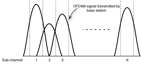
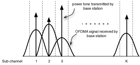
Next, consider SWIPT with uplink IT. As illustrated in Fig. 2(b), downlink MPT relies on the transmission of power tones at the centers of the corresponding sub-channels and their sum power satisfies the power constraint in (1). For a single-user system, the power tones are beamed by the base station to a mobile. Besides operating the circuit, the mobile uses part of the harvested power to enable uplink IT where the uplink data signal is OFDM modulated as shown in Fig. 2(b). For a multi-user system, the power tones are beamed to corresponding mobiles. The uplink transmission by the mobiles is based on OFDMA.
III SWIPT-Enabled Mobile Architecture
In this section, we propose a dual-antenna mobile architecture as illustrated in Fig. 3 for supporting dual-mode SWIPT. The architecture comprises a transceiver and an energy harvester. The transceiver demodulates and decodes received data for downlink IT or encodes and modulates data for uplink IT. The energy harvester converts the input signal into DC power for operating the circuitry. The architecture can be reconfigured depending on whether the IT takes place in the uplink or downlink direction.
Consider the architecture configured for downlink IT. The antenna outputs are then coherently combined to enhance the received signal power (see Fig. 3). The combiner output is split into inputs to the receiver and to the energy harvester [12]. To be specific, the received signal is split using a power splitter that multiplies the signal with the adjustable factors and , where , in order to obtain the inputs to the receiver and the energy harvester, respectively. Consequently, the received power is divided into two parts of relative magnitudes and . Let and represent the variances of the noise for a sub-channel, as accumulated in the path before and after the splitter, respectively. To simplify notation, we assume that the total noise has unit variance and thus . Using these definitions, the receive SNR for the -th stream can be written as [11]
| (2) |
where due to the maximum-ratio combining. Neglecting the small contributions from noise and beam sidelobes, and assuming lossless RF-to-DC conversion, the harvested power at a mobile is for a single-user system and for a multi-user system where the mobile is assigned the -th sub-channel.
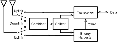
Next, for the mobile architecture configured for uplink IT, two antennas are separately attached to the transceiver and energy harvester to support the full-duplex operation of the information and power transfers in the opposite directions (see Fig. 3). Under the assumption of unit noise variance, the receive SNR at the base station for the -th stream is where represents the uplink-transmission power allocated to the -th sub-channel. The harvested power at a mobile is for the single-user system and for the multi-user system when the mobile is assigned the -th sub-channel.
Finally, it is worth mentioning that adding more antennas at a mobile enhances the received signal power by increasing the total antenna aperture as well as providing an array gain for the uplink transmission. Nevertheless, spatial multiplexing is difficult since a typical environment for efficient MPT has line-of-sight and the corresponding channel matrix is practically rank-one.
IV Power Control for Single-User SWIPT Systems with Downlink IT
IV-A Single-User Downlink IT with Variable Coding Rates
IV-A1 Problem formulation
Given the receive SNR in (2), the downlink throughput, denoted as , can be written as
| (3) |
where the indicator function gives if the event occurs and otherwise. The indicator function in (3) represents the circuit power constraint. The problem of maximizing the throughput in (3) by power control is formulated as:
IV-A2 Solution
P1 is non-convex but can be approximated by a convex problem as follows. Since, by assumption, , the rate function in P1 is bounded as
| (4) | ||||
Approximating the objective function in P1 using the lower bound in (4) yields
The alternative approximation using the upper bound in (4) has the same structure as P1.1 and hence is omitted for brevity. Moreover, both approximations give nearly optimal power control policies as showed by simulation. P1.1 is a convex problem and can be solved numerically by standard algorithms for convex optimization [24]. In the remainder of this section, we investigate the structure of the power control policy that solves P1.1.
First, it is necessary to test the feasibility of powering the receiver given transmission power . This requires computing the limit of the harvested power by solving the following optimization problem:
By inspecting P1.1, it is found that . It follows that SWIPT is feasible if and only if
| (5) |
Next, given the feasibility condition in (5), fixing in P1.1 leads to
P1.3 can be solved using the method of duality and the solution is [24]
| (6) |
where the set is chosen to ensure being non-negative, and the positive scalars and are the Lagrange multipliers solving the dual problem – the unconstrained minimization of the following convex function [24]:
Note that the index set in (6) can be obtained by repetitively removing from the index of the mobile corresponding to the smallest negative element of and then recomputing and till the set contains only nonnegative elements. It follows from (6) that there exists a such that the solution to P1.3, denoted as , can be written as
| (7) |
where , and . As a result, the optimal power-control policy for the current case can be approximated as for all . Simulation shows that such an approximation yields a throughput very close to the maximum possible. The power allocation in (7) can be interpreted as water-filling in frequency with a water level that decreases with an increasing sub-channel gain or vice versa. This agrees with the intuition that less transmission power is required for turning on a receiver if the MPT loss is smaller. In contrast, the classic water-filling has a constant water level.
IV-B Single-User Downlink IT with Fixed Coding Rates
IV-B1 Problem formulation
The downlink throughput, denoted as , is proportional to the number of successfully transmitted streams. Specifically, using the receive SNR in (2), is written as
| (8) | ||||
where the first indicator function represents the circuit-power constraint and the sum gives the number of correctly decoded streams. The problem of maximizing by power control is hence formulated as:
IV-B2 Solution
Solving P2 is equivalent to finding the maximum number of successfully transmitted streams, denoted as and derived as follows. First, rearrange the sequence of channel gains in descending order and denote the result as . The corresponding transmission powers are . This reordering can be represented by the permutation matrix such that
| (9) |
where the superscript denotes the matrix transposition. Assume that streams are successfully transmitted. Let represent the power needed to successfully transmit the -th stream such that the total power is minimized. To this end, it is desirable to transmit the streams over sub-channels with the largest channel gains, namely, . Therefore, considering the minimum-SNR constraint, solves the following optimization problem:
Replacing the the inequality constraints in P2.1 results in an optimization problem with a smaller domain:
| (10) |
Comparing P2.1 and P2.2 reveals that if the domain of P2.2 is nonempty, the solution to P2.2 must also solve P2.1. The existence of a solution for P2.2 can be tested by solving the system of linear equations from the equality constraints. As a result, satisfies the following quadratic equation:
| (11) |
where the coefficients and are
| (12) |
Solving the equation in (11) and choosing the positive root give the optimal value of for a given , denoted as :
| (13) |
Since the quadratic function on the left hand side of (11) is negative for and positive for , lies in the range and hence is a valid value for the splitting ratio. This confirms the existence of a unique solution for P2.2 (equivalently P2.1) that follows from the equality constraints in P2.2 as
| (14) |
and the minimum transmission power for supporting streams is hence . In other words, the optimal policy performs greedy channel inversion.
We can now solve P2 by obtaining as the maximum value of under the power constraint from (1), which involves a simple search. To be specific
| (15) |
with given in (14). Note that if for which it is infeasible to transmit any stream. It follows from (15) that the solution to P2, is given as
| (16) | ||||
The main results of this section are summarized in the following proposition.
V Power Control for Single-User SWIPT Systems with Uplink IT
V-A Single-User Uplink IT with Variable Coding Rates
V-A1 Problem formulation
Uplink transmission is feasible provided that the harvested power exceeds the circuit power: . Under this condition, the total uplink transmission power is that is allocated over sub-channels for maximizing the uplink throughput. In other words, the throughput for the current case can be written as
| (17) |
where satisfies the power constraint in (1) and represents uplink power control subject to:
| (18) |
Using (17), the problem of maximizing the uplink throughput is formulated as
V-A2 Solution
By inspecting P3, the optimization problem can be decomposed into two sub-problems:
and
where solves P3.1. The two problems have different objectives: That of P3.1 is to maximize the downlink transferred power and that of P3.2 is to maximize the uplink throughput. P3.1 is similar to P1.2 and it is straightforward to show that
| (19) |
and that the transferred power is . It follows that the feasibility condition for the uplink transmission is
| (20) |
which is similar to that in (5). Under this condition and given (19), P3.2 reduces to the classic multi-channel power control problem with the water-filling solution given by
| (21) |
where the set contains the indices of the uplink sub-channels assigned nonzero power, and is the water level chosen such that . The solution to P3 is summarized in the following proposition.
Proposition 2.
Consider the single-user SWIPT systems with uplink IT and variable coding rates.
-
1.
The optimal power-control policy at the base station is to maximize the MPT efficiency by transferring the maximum power over a single tone in the downlink sub-channel with the maximum effective channel gain, resulting in the transferred power equal to .
- 2.
V-B Single-User Uplink IT with Fixed Coding Rates
V-B1 Problem formulation
V-B2 Solution
Similar to P3, P4 can be decomposed into two sub-problems. The first sub-problem maximizes the transferred power in the downlink and is identical to P3.1. It follows that uplink transmission is feasible if and only if the condition in (20) is satisfied, namely that . Under this condition, the other sub-problem is to maximize the uplink throughput, more exactly:
It can be observed from P4.1 that the optimal power allocation should be again based on greedy channel inversion. Specifically, the optimal policy attempts to meet the minimum-SNR constraints of the streams following the descending order of their corresponding sub-channel gains . To state the policy mathematically, let the sequence represent the values of sorted in descending order. Let represent the permutation matrix such that
Following the earlier discussion, the power allocated to the sub-channels with gains , denoted as , is given as
| (23) |
where , , is the maximum number of uplink streams under the uplink-power constraint obtained from the first constraint in P4.1 as
| (24) |
The solution to P4 is summarized in the following proposition.
Proposition 3.
Consider the single-user SWIPT system with uplink IT and fixed coding rates.
VI Power Control for Multi-User SWIPT Systems with Downlink IT
VI-A Multi-User Downlink IT with Variable Coding Rates
VI-A1 Problem formulation
Using the receive SNR in (2), the sum throughput is obtained as
| (25) |
In contrast to the single-user counterpart in (3) having a single circuit-power constraint, the sum throughput in (25) contains multi-user circuit-power constraints. The corresponding power-control problem is formulated as follows:
VI-A2 Solution
Like P1, P5 is non-convex but can be approximated by a convex problem by replacing the objective function by either the lower or upper bounds in (4). Both approximating problems have the same structure and yield practically the same solutions as P5, as shown by simulation. For brevity, we consider only the approximation of P5 using the lower bound in (4) and hence solving the following problem:
It can be observed from P5.1 that if , it is optimal to choose such that the input power to the energy harvester is since additional power contributes no throughput gain, corresponding to . Consequently, P5.1 can be rewritten as
Let denote the indices of the mobiles that meet their circuit-power constraints using the power allocation in the solution of P5. Given and defining , P5.2 can be simplified as
As the values of increase, the objective function in P5.3 increases and the first constraint is relaxed. It follows that with , P5.3 is equivalent to
where . The form of P5.4 is similar to that of the traditional multi-channel power control problem with the key difference that the maximum of increases with decreasing . The reason is that reducing the number of streams decreases the total circuit-power consumption of the system and thereby allows more power to be used for IT. Given , combining the traditional water-filling method and the constant if yields the solution to P5.4 as follows:
| (26) |
The corresponding sum throughput is
Next, the number of streams is determined by a simple search. According to the traditional water-filling method, is chosen as where with is the largest integer such that are positive. It is important to note that the traditional choice may not be optimal due to the aforementioned difference between the traditional method and P5.4. In other words, reducing the number of streams below may result in a throughput gain. The optimal value of , however, has no closed-form solution but can be obtained by a simple search over the range from to . To be specific, the value of that maximizes the sum throughput is given as
| (27) |
The above results are summarized in the following lemma.
Lemma 1.
Since P5.1 is a convex approximation of P5, the solution or equivalently the optimal power-control policy for the current case can be approximated as for all , which is shown by simulation to be close-to-optimal.
VI-B Multi-User Downlink IT with Fixed Coding Rates
VI-B1 Problem formulation
VI-B2 Solution
Replacing the inequalities in P6 with equalities has no effect on the solution. Hence, P6 can be rewritten as
The splitting ratio for the -th mobile can be obtained by solving the following two linear equations:
The resulting optimal value of , which is identical for all mobiles and denoted as , has a similar form as the single-user counterpart in (13):
| (28) |
where the coefficients and are as given in (12). With fixed as given in (28), it follows from inspecting P6 that the optimal power-control policy again performs greedy channel inversion, just like its single-user counterpart. The result is summarized in the following proposition.
Proposition 4.
For the multi-user SWIPT system with downlink IT, the optimal power-control policy, represented by , is given as
| (29) |
where
| (30) |
The optimal splitting ratio is given by (28) and , , is the largest integer such that the power constraint
| (31) |
is satisfied.
VII Power Control for Multi-User SWIPT Systems with Uplink IT
VII-A Multi-User Uplink IT with Variable Coding Rates
VII-A1 Problem formulation
The sum throughput for the current case is given as
| (32) |
Note that the product in (32) represents the combined loss due to propagation both in the downlink and in the uplink. This must be contrasted with the loss of only in the case of downlink IT [see (25)]. The power-control problem is formulated using (32) as
VII-A2 Solution
To facilitate a compact exposition, we use the following definitions. Let denote the downlink sub-channel gains sorted in descending order and let be the corresponding permutation matrix; that is, we have:
| (33) |
Arranging the uplink sub-channel gains in the same way, i.e., , gives
| (34) |
The powers are defined based on in a similar way. Using these definitions, P7 can be rewritten as
Given that P7.1 is non-convex, a sub-optimal algorithm is proposed as follows. Assume that mobiles are active, that is, they harvest sufficient energy for meeting their circuit-power constraints; all others are allocated zero power. To maximize the MPT efficiency, the active mobiles are chosen to be those corresponding to the largest downlink sub-channel gains . This choice may not be overall optimal, however, since selecting a mobile with relative small downlink but sufficiently large uplink sub-channel gains can increase the throughput. Define . Given the assumptions and choices made, the problem of maximizing the uplink sum throughput reduces to the standard multi-channel power control problem:
This problem is solved by water-filling:
| (35) |
The number of active mobile is optimized. Let , , be the maximum number of active mobiles such that the corresponding multi-user circuit-power constraints and the power constraint are satisfied:
| (36) |
For the same reason as discussed when solving P5.4, it may not be optimal to set the optimal value of , denoted as , as . Instead, can be found by testing the values . The above results are summarized in the following algorithm for computing a sub-optimal solution for P7.
Algorithm 1.
-
1.
Compute the maximum number of active mobiles .
- 2.
-
3.
Given , the allocated powers are computed as
(38) Then rearrange to give the power allocation :
Algorithm sequentially performs the tasks of scheduling mobiles with high MPT efficiencies and maximizing the uplink sum rate of the scheduled mobiles by power control. The design exploits the fact that meeting the circuit power constraints is a prerequisite for IT and hence has high priority. Such a sequential algorithm provides a close-to-optimal solution as shown by simulation results in the sequel.
VII-B Multi-User Uplink IT with Fixed Coding Rates
VII-B1 Problem formulation
The sum throughput for the current scenario can be written as
| (39) |
The corresponding formulation of the optimal power-control problem follows as
VII-B2 Solution
Since the the first indicator function in the objective function of P8 yields if and only if the second does so, P8 reduces to
For ease of notation, define the scalar sequence according to
| (40) |
and the vector . Let represent the sequence sorted in ascending order, and define the vector and the permutation matrix such that . By inspecting P8, the optimal power control policy at the base station is found to be the one that attempts to meet the minimum-SNR requirements of the uplink streams following the descending order of . To be specific, the optimal power allocated to the sub-channel corresponding to , denoted as , is given as
| (41) |
where is the maximum number of uplink streams or equivalently the largest integer for which the power constraint obtained from (1),
| (42) |
is satisfied. Note that the policy as specified by (41) is a variant of greedy channel inversion where combines the inversion of closed-loop channels and circuit-power consumption. Then the solution to P8 follows from rearranging according to the original order of the sub-channels. In other words,
| (43) |
with in (41). The key results of this section are summarized in the following proposition.
Proposition 5.
Consider the multi-user SWIPT system with uplink IT and fixed coding rates.
-
1.
The optimal power-control policy at the base station is given by (43).
-
2.
It is optimal for each active mobile harvesting nonzero power to apply all available power for uplink transmission after deducting the power needed to operate its circuitry.
VIII Simulation Results
In this section, the performance of SWIPT using the power-control algorithms proposed in the preceding sections is evaluated by simulation in terms of spectral efficiency versus circuit power. The channel model is described as follows. Propagation is assumed to have line-of-sight and be close to that in free space, which is necessary for making MPT feasible. The propagation model for beamed transmission is modified from that in [25] and specified by the following relation between the transmission power and received power for an arbitrary link:
| (44) |
where is the wavelength, and the total apertures of the transmit and receive antenna arrays, respectively, the transmission distance and a complex Gaussian random variable with nonzero mean that models small-scale fading. For simulation, it is assumed that the wavelength corresponds to a carrier frequency of GHz, the total aperture of the base-station antenna array is sq. m, the aperture of each of the two antennas at a mobile is sq. m, the base-station transmission power is W in the single-user system and W in the multi-user system, and follows the distribution. For the scenario of uplink IT, the two sub-arrays at the base station that support full-duplex MPT/IT are assumed to have equal apertures of sq. m. For efficient MPT, transmission distances are assumed to be short as enabled by dense base-station deployment. To be specific, the distances are m for the single-user system and m for the multi-user system with five mobiles. Correspondingly, there are five frequency sub-channels which are assumed to be frequency non-selective. Their bandwidth has no effect on the simulation results since the performance metric is spectral efficiency. The distributions of the channel coefficients follow from the propagation model in (44). To be specific, each coefficient is given by the expression of in (44) substituted with the corresponding transmission distance, and all coefficients are assumed to be independent. Note that the beamforming gains are accounted for in the model of the channel coefficients via the antenna apertures [25]. Given short propagation distances and line-of-sight channels, a mobile in can be exposed to extremely strong interference and hence the interference-plus-noise variance from each sub-channel is chosen to have a large value, namely dBm, where and of the noise power are introduced before and after a power splitter (see Fig. 3), respectively. Note that in an interference dominant environment, the interference-plus-noise variance is largely determined by the ratio between the main-lobe and side-lobe responses rather than the channel bandwidth that affects the thermal noise variance. The SNR threshold for the case of a fixed coding rate is set as dB for the scenario of downlink IT and dB for the scenario of uplink IT, which are optimized numerically to enhance the spectral efficiency. Last, the battery capacity at all mobiles is assumed to be sufficiently large such that there is no energy loss due to battery overflow.
The proposed SWIPT with power control is compared in the sequel with SWIPT without such control (equal power allocation) as well as the TD-IPT method [11, 19]. It is assumed for TD-IPT that each time slot is divided into two halves for alternating MPT and IT. The time sharing reduces the duration for IT by half but enhances the received signal power by dedicating all antennas to either MPT or IT at each time instant. The power control algorithms for TD-IPT follow straightforwardly from those designed for SWIPT and thus the details are omitted for brevity.
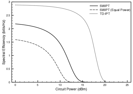
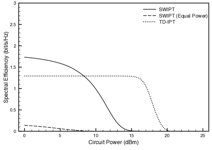
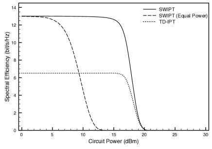
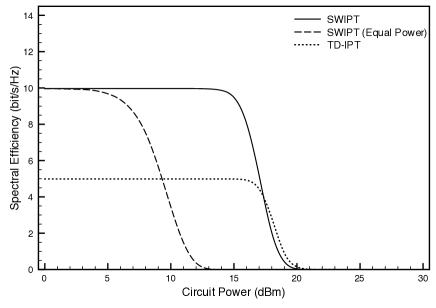
First, consider the scenario of SWIPT with downlink IT. The curves of spectral efficiency versus circuit power are plotted in the sub-figures in Fig. 4, corresponding to different cases combining single-user/multi-user systems and variable/fixed coding rates. For all the curves in the figure, as the circuit power decreases, the spectral efficiencies converge to their counterparts for the case with reliable power supplies at the mobiles, which are extremely high ( bit/s/Hz) due to the low propagation loss. The spectral efficiencies reduce with increasing circuit power. In particular, the changes exhibit a threshold effect for the single-user system (see top sub-figures in Fig. 4). This suggests that powering one passive mobile by MPT has little effect on the spectral efficiency if the circuit power is below the threshold, but otherwise it degrades the efficiency severely. However, for the multi-user system, since the base-station needs to power multiple mobiles, the spectral efficiency is sensitive to the changes in the circuit power (see bottom sub-figures in Fig. 4). Next, comparing SWIPT with and without power control, it is observed that with the spectral efficiency fixed such control can increase circuit power substantially e.g., by up to about dB for the single-user system. Last, though TD-IPT yields spectral efficiencies about half of those by SWIPT for low to moderate circuit power, the gap narrows as the power increases and TD-IPT can outperform SWIPT for high circuit power as shown in the case of the single-user system with fixed coding rates.
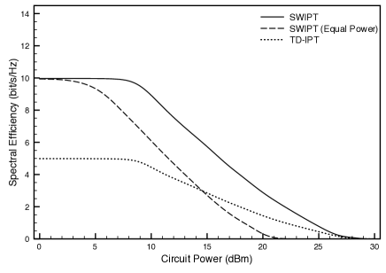
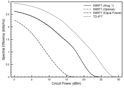
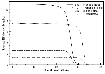
Next, consider the scenario of SWIPT with uplink IT. A similar set of curves as those in Fig. 4 are plotted in Fig. 5. Compared with the previous scenario of SWIPT with downlink IT, the power supplied by the base station must overcome a roundtrip propagation loss, first for the MPT in the downlink and then for the IT in the uplink, which decreases the spectral efficiencies by more than bit/s/Hz. For the current scenario, TD-IPT is found to outperform SWIPT. This suggests that given severe propagation loss it should be preferable to use all transmit/receive antennas for either MPT or IT which more than compensates the time-sharing loss. Last, the performance of the sub-optimal Algorithm designed for the case of multi-user SWIPT with uplink IT is observed to be close-to-optimal, where the curve for the optimal algorithm is obtained by scheduling based on an exhaustive search for maximizing the spectral efficiency.
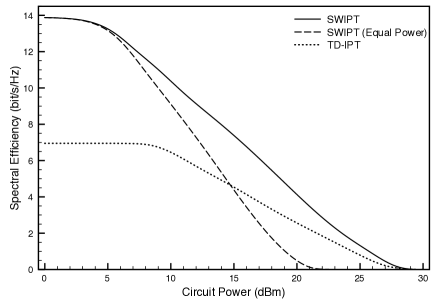
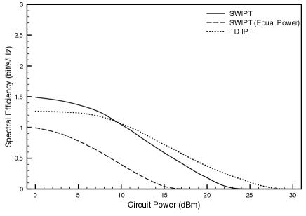
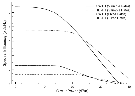
For the same scenario of uplink IT, a further comparison between TD-IPT and SWIPT is provided in Fig. 6 for which the round-trip propagation loss is alleviated by reducing all transmission distances by five times. It is observed that there are intersections between the curves for SWIPT and their TD-IPT counterparts. This leads to the conclusion that SWIPT is preferred when the propagation loss is not extremely severe (e.g., for the case of downlink IT) or the circuit power is low; otherwise, TD-IPT should be used for a higher spectral efficiency.
IX Conclusions
A framework has been proposed for realizing SWIPT in a broadband wireless system that comprises a passive SWIPT-enabled mobile architecture and a matching set of power-control algorithms designed for different system configurations accounting for single-user/multi-user systems, variable/fixed coding rates, and uplink/downlink information transfer. These algorithms have been optimized for maximizing the system throughput under circuit-power constraints at mobiles, in addition to a power constraint at the base station. It is shown by simulation that power control plays an important role in enhancing the efficiency of SWIPT.
This work can be extended in several interesting directions. First, the channel assignment was assumed to be fixed here. Jointly assigning channels and performing optimal power control may further increase the SWIPT efficiency. Second, the current framework can be modified to support multimode operations including MPT or SWIPT to nearby mobiles but only information transfer to mobiles far away. Third, the power control can be integrated with intelligent energy management policies at the mobiles, in order to exploit the diversity that originates from time-variations of the channels. Finally, it would be interesting to design a framework for cooperative SWIPT in a multi-cell system.
References
- [1] W. C. Brown, “The history of power transmission by radio waves,” IEEE Trans. on Microwave Theory and Techniques, vol. 32, pp. 1230–1242, Sep. 1984.
- [2] J. O. Mcspadden and J. C. Mankins, “Space solar power programs and microwave wireless power transmission technology,” IEEE Microwave Magazine, vol. 3, pp. 46–57, Apr. 2002.
- [3] J. J. Schlesak, A. Alden, and T. Ohno, “A microwave powered high altitude platform,” IEEE MTT-S Digest, pp. 283–286, 1988.
- [4] T. Le, K. Mayaram, and T. Fiez, “Efficient far-field radio frequency energy harvesting for passively powered sensor networks,” IEEE Journal of Solid-State Circuits, vol. 43, pp. 1287–1302, May 2008.
- [5] “P2110 - 915MHz RF powerharvester receiver,” Product Datasheet, Powercast Corp., pp. 1–12, 2010.
- [6] F. Balouchi and B. Gohn, “Wirelss power,” Pike Research Report, 2Q 2012.
- [7] F. Rusek, D. Persson, B. K. Lau, E. G. Larsson, T. L. Marzetta, O. Edfors, and F. Tufvesson, “Scaling up MIMO: Opportunities and challenges with very large arrays,” IEEE Signal Proc. Magazine, vol. 30, pp. 40–60, Jan. 2013.
- [8] L. R. Varshney, “Transporting information and energy simultaneously,” in Proc., IEEE Intl. Symposium on Information Theory, pp. 1612–1616, Jul. 2008.
- [9] P. Grover and A. Sahai, “Shannon meets Tesla: Wireless information and power transfer,” in Proc., IEEE Intl. Symposium on Information Theory, pp. 2363–2367, Jun. 2010.
- [10] A. Fouladgar and O. Simeone, “On the transfer of information and energy in multi-user systems,” IEEE Comm. Letters, vol. 16, pp. 1733–1736, Nov. 2012.
- [11] R. Zhang and C. Ho, “MIMO broadcasting for simultaneous wireless information and power transfer,” IEEE Tarns. on Comm., vol. 12, pp. 1989–2001, May 2013.
- [12] X. Zhou, R. Zhang, and C. Ho, “Wireless information and power transfer: Architecture design and rate-energy tradeoff,” submitted to IEEE Tarns. on Comm. (Avaiable: http://arxiv.org/abs/1205.0618), 2012.
- [13] Z. Xiang and M. Tao, “Robust beamforming for wireless information and power transmission,” IEEE Wireless Comm. Letters, vol. 1, pp. 372–375, Apr. 2012.
- [14] P. Popovski, A. Fouladgar, and O. Simeone, “Interactive joint transfer of energy and information,” IEEE Trans. on Comm., vol. 61, pp. 2086–2097, May 2013.
- [15] B. Gurakan, O. Ozel, J. Yang, and S. Ulukus, “Energy cooperation in energy harvesting wireless communications,” in Proc., IEEE Intl. Symposium on Information Theory, pp. 965–969, 2012.
- [16] K. Huang and V. K. N. Lau, “Enabling wireless power transfer in cellular networks: Architecture, modeling and deployment,” submitted to IEEE Trans. on Wireless Comm. (Available: http://arxiv.org/abs/1207.5640).
- [17] A. Goldsmith, Wireless Communications. Cambridge University Press, 2005.
- [18] K. Huang and E. G. Larsson, “Simultaneous information-and-power transfer for broadband downlink systems,” in Proc., IEEE Intl. Conf. on Acoustics, Speech, and Signal Processing, May 2013.
- [19] D. W. Ng, E. S. Lo, and R. Schober, “Energy-efficient resource allocation in multiuser OFDM systems with wireless information and power transfer,” in Proc., IEEE Wireless Comm. and Networking Conf., Apr. 2013.
- [20] J. Choi, M. Jain, K. Srinivasan, P. Levis, and S. Katti, “Achieving single channel, full duplex wireless communication,” in Proc., Intl. Conf. on Mobile Comp. and Networking, Sep. 20-24 2010.
- [21] G. Miao, N. Himayat, Y. G. Li, and A. Swami, “Cross-layer optimization for energy-efficient wireless communications: A survey,” Wireless Comm. and Mobile Computing, vol. 9, pp. 529–542, Apr. 2009.
- [22] C. Y. Wong, R. Cheng, K. Lataief, and R. Murch, “Multiuser OFDM with adaptive subcarrier, bit, and power allocation,” IEEE Journal on Selected Areas in Comm., vol. 17, pp. 1747–1758, Oct. 1999.
- [23] L. H. Ozarow, S. Shamai, and A. D. Wyner, “Information theoretic considerations for cellular mobile radio,” IEEE Trans. on Veh. Technology, vol. 43, pp. 359–378, May 1994.
- [24] S. Boyd and L. Vandenberghe, Convex Optimization. Cambridge, UK: Cambridge, 2004.
- [25] C. W. Brown and E. E. Eves, “Beamed microwave power transmission and its application to space,” IEEE Transactions on Microwave Theory and Techniques, vol. 40, pp. 1239–1250, Jun. 1992.
![[Uncaptioned image]](/html/1211.6868/assets/Huang.jpg) |
Kaibin Huang (S’05, M’08, SM’13) received the B.Eng. (first-class hons.) and the M.Eng. from the National University of Singapore in 1998 and 2000, respectively, and the Ph.D. degree from The University of Texas at Austin (UT Austin) in 2008, all in electrical engineering. Since Jul. 2012, he has been an assistant professor in the Dept. of Applied Mathematics (AMA) at The Hong Kong Polytechnic University (PolyU), Hong Kong. He had held the same position in the School of Electrical and Electronic Engineering at Yonsei University, S. Korea from Mar. 2009 to Jun. 2012 and presently is affiliated with the school as an adjunct professor. From Jun. 2008 to Feb. 2009, he was a Postdoctoral Research Fellow in the Department of Electrical and Computer Engineering at the Hong Kong University of Science and Technology. From Nov. 1999 to Jul. 2004, he was an Associate Scientist at the Institute for Infocomm Research in Singapore. He frequently serves on the technical program committees of major IEEE conferences in wireless communications. He will chair the Comm. Theory Symp. of IEEE GLOBECOM 2014 and the Adv. Topics in Wireless Comm. Symp. of IEEE/CIC ICCC 2014, and has been the technical co-chair for IEEE CTW 2013, the track chair for IEEE Asilomar 2011, and the track co-chair for IEE VTC Spring 2013 and IEEE WCNC 2011. He is a guest editor for the IEEE Journal on Selected Areas in Communications, and an editor for the IEEE Wireless Communications Letters and also the Journal of Communication and Networks. He is an elected member of the SPCOM Technical Committee of the IEEE Signal Processing Society. Dr. Huang received the Outstanding Teaching Award from Yonsei, Motorola Partnerships in Research Grant, the University Continuing Fellowship at UT Austin, and Best Paper Awards from IEEE GLOBECOM 2006 and PolyU AMA. His research interests focus on the analysis and design of wireless networks using stochastic geometry and multi-antenna limited feedback techniques. |
![[Uncaptioned image]](/html/1211.6868/assets/Larsson.jpg) |
Erik G. Larsson received his Ph.D. degree from Uppsala University, Sweden, in 2002. Since 2007, he is Professor and Head of the Division for Communication Systems in the Department of Electrical Engineering (ISY) at Linköping University (LiU) in Linköping, Sweden. He has previously been Associate Professor (Docent) at the Royal Institute of Technology (KTH) in Stockholm, Sweden, and Assistant Professor at the University of Florida and the George Washington University, USA. His main professional interests are within the areas of wireless communications and signal processing. He has published some 100 journal papers on these topics, he is co-author of the textbook Space-Time Block Coding for Wireless Communications (Cambridge Univ. Press, 2003) and he holds 10 patents on wireless technology. He is Associate Editor for the IEEE Transactions on Communications and he has previously been Associate Editor for several other IEEE journals. He is a member of the IEEE Signal Processing Society SPCOM technical committee. He is active in conference organization, most recently as the Technical Chair of the Asilomar Conference on Signals, Systems and Computers 2012 and Technical Program co-chair of the International Symposium on Turbo Codes and Iterative Information Processing 2012. He received the IEEE Signal Processing Magazine Best Column Award 2012. |