Transmission Line Analogy for Relativistic Poynting-Flux Jets
Abstract
Radio emission, polarization, and Faraday rotation maps of the radio jet of the galaxy 3C 303 have shown that one knot of this jet carries a galactic-scale electric current and that it is magnetically dominated. We develop the theory of magnetically dominated or Poynting-flux jets by making an analogy of a Poynting jet with a transmission line or waveguide carrying a net current and having a potential drop across it (from the jet’s axis to its radius) and a definite impedance which we derive. The electromagnetic energy flow in the jet is the jet impedance times the square of the jet current. The observed current in 3C 303 can be used to calculate the electromagnetic energy flow in this magnetically dominated jet. Time-dependent but not necessarily small perturbations of a Poynting-flux jet are described by the “telegrapher’s equations.” These predict the propagation speed of disturbances and the effective wave impedance for forward and backward propagating wave components. A localized disturbance of a Poynting jet gives rise to localized dissipation in the jet which may explain the enhanced synchrotron radiation in the knots of the 3C 303 jet, and also in the apparently stationary knot HST-1 in the jet near the nucleus of the nearby galaxy M87. For a relativistic Poynting jet on parsec scales, the reflected voltage wave from an inductive termination or load can lead to a backward propagating wave which breaks down the magnetic insulation of the jet giving . At the threshold for breakdown, , positive and negative particles are directly accelerated in the direction which is approximately along the jet axis. Acceleration can occur up to Lorentz factors . This particle acceleration mechanism is distinct from that in shock waves and that in magnetic field reconnection.
keywords:
galaxies: jets — accretion discs — magnetic fields — acceleration of particles1 Introduction
A fundamental open question of astrophysical jet models is how energy extracted from the accretion flow close to the black hole event horizon is transported along narrow jets to much larger distances. The total energy carried by the jets of active galaxies is estimated to be a non-negligible fraction of the massive black hole formation energy, (Kronberg et al. 2001). The jets are initially highly relativistic and low-density and for this reason are magnetically dominated or force-free. In this limit a negligible fraction of the power is carried by the particle kinetic energy. That is, the energy outflow from the accretion disc is in the form of a collimated ‘Poynting-flux jet’ as proposed by Lovelace (1976) and subsequently studied in many papers (Benford 1978; Lovelace, Wang, & Sulkanen 1987; Lynden-Bell 1996; Li, et al. 2001; Lovelace, et al. 2002; Lovelace & Romanova 2003; Nakamura et al. 2008).
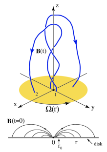
An illustrative model for the formation of a relativistic Poynting jet is sketched in Fig. 1. A large scale magnetic field is assumed to thread the accretion disc. As a result of the differential rotation of the disc the initial field loops opens up giving a current outflow (or inflow) along the spine of the jet of cylindrical radius initially of the order of the Schwarzschild radius of the black hole (Lovelace & Romanova 2003). A three-dimensional view of a numerically calculated magnetic field is shown in Fig. 6 of Lovelace et al. (2002). In this model the jet power comes from the accretion disc. The associated toroidal magnetic field is responsible for collimating the jet. An equal but opposite “return current” flows inward (or outward) at much larger radial distances from the jet axis so that the net current outflow from the source is zero. Because the jet current and the return current have opposite signs they repel as a result of their magnetic interaction mediated by the toroidal magnetic field. This repulsion between the jet and its return current has been demonstrated in magnetohydrodynamic (MHD) simulations (Ustyugova et al. 2000; Nakamura et al. 2008). The energy flow in the jet is unidirectional and is carried predominantly by the Poynting flux (MKS units), where is the radial electric field of the jet. The power in the Poynting jet may come predominantly from the spin-down of the black hole (Blandford & Znajek 1977). This process, which depends on the presence of a magnetized accretion disc around the rotating black hole, has been studied with general relativisitic MHD simulations (e.g., McKinney 2006; Beckwith, Hawley, & Krolik 2008; Tcchekhovskoy, Narayan, & McKinney 2011).
Rotation measure gradients observed on parsec scales close to the nuclear central black hole have given evidence of electric current flow along the jets (Asada et al. 2002; Gabuzda, Murray, & Cronin 2004; Zavala & Taylor 2005). More recently, on a scale times larger, radio emission, polarization, X-ray, and Faraday rotation maps of the radio jet of the galaxy 3C 303 have shown that one knot of this jet has a galactic-scale current of Ampère flowing along the jet axis (Kronberg et al. 2011). The physical parameters of this knot derived from the observations indicate that the jet is magnetically dominated, that is, a Poynting jet. The existence of an axial current in this very large scale plasma flow suggests an electrical circuit analogy for the jet.
A further possible indication of a Poynting jet is the jet near the nucleus of the galaxy M87 which has been observed to have an apparently stationary but strongly time-dependent knot HST-1 in its jet (Biretta et al. 1999). This knot showed a dramatic peak in emission in about 2005.2 in the radio, optical, and X-ray bands (Harris et al. 2009).
In Sec. 2 we model a Poynting jet as a transmission line carrying a net axial current and having a potential drop across it. Further, we derive the transmission line impedance and the electromagnetic energy flow in the jet. Time-dependent but not necessarily small perturbations of a Poynting-flux jet (§2.2) are described by the “telegraphers’ equations” (Heaviside 1893). These are wave equations for the current and voltage across the line. The voltage and current consist in general of forward and backward propagating components. A localized irregularity of a Poynting jet (§2.3) can give rise to localized dissipation in the jet which may explain the enhanced synchrotron radiation in the knots of the 3C 303 jet and in the apparently stationary knot HST-1 in M87.
Secs. 2.4 & 2.5 consider highly relativistic Poynting jets on parsec-scales jets such as HST-1. In this case the reflected voltage wave from an inductive load can lead to a backward propagating wave which breaks down the magnetic insulation of the jet, giving . The threshold for this breakdown is . At this threshold, positive and negative particles are directly accelerated in the direction which is approximately along the jet axis and can be accelerated to very high Lorentz factors. Sec. 3 gives conclusions of this work.
2 Theory
In cylindrical coordinates with axisymmetry assumed, the magnetic field has the form with , and and Here, is the flux function. A simple form of this function is where is the axial magnetic field strength in the center of the disc, and is the radius of the point of the magnetic field in the plane of the disc as indicated in Fig. 1. This is taken to apply for even though it is not valid near the horizon of the black hole. The contribution from this region is negligble for the considered conditions where , with . For a corotating disc around a Kerr black hole the disc’s angular velocity viewed from a large distance is for where is the innermost stable circular orbit and is the spin parameter of the black hole with .
At large distances from the disc () the flux function solution of the ‘force-free’ Grad-Shafranov equation is
| (1) |
(Lovelace & Romanova 2003). The ‘force-free’ solution is applicable for conditions where the kinetic energy-density of the plasma is much less than the magnetic energy-density. Here is the Lorentz factor of the jet, , with , and . This dependence holds for At the inner radius , , which corresponds to the streamline which passes through the disc at a distance . For , we assume , which corresponds to const. At the outer radius , which corresponds to the streamline which goes through the disc near the point at . Note that there is an appreciable range of radii if . Also note that for , radiation drag on the lepton component of the jet is negligible.
For , the field components of the Poynting jet are
and
| (2) |
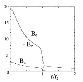
This electromagnetic field satisfies the radial force balance equation, , for an axisymmetric, translationally-symmetric, and time-independent force-free field. Figure 2 shows the field profiles.
Appendix A describes a different force-free jet model with electric and magnetic fields similar to those in a common coaxial transmission line.
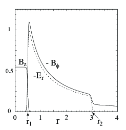
At the jet radius , there is a boundary layer where the axial magnetic field changes from to zero at , where is the half-width of this layer. The electric field changes from to zero at . The toroidal magnetic field changes from to where this change is fixed by the radial force balance. Thus for , we have , , and . Equivalently, .
The toroidal magnetic field for applies out to an ‘outer radius’ where the magnetic pressure of the jet’s toroidal magnetic field, , balances the external ram pressure , where is the kinetic pressure of the external intergalactic plasma and is its density. The outward propagation of the jet will be accompanied by the non-relativistic expansion of the outer radius, .
We take as the ‘jet current’ the axial current flowing along the jet core . From Ampère’s law, or in convenient units, . The net current carried by the jet () is .
Using equations (2), the energy flux carried by the Poynting jet can be expressed as
| (3) |
where the square bracket is for cgs or MKS units, and
| (4) |
where . Here, is the DC impedance of the Poynting jet. The conversion to MKS units is Earlier, the impedance of a relativistic Poynting jet was estimated to be (Lovelace 1976).
We can apply these concepts to the jet in 3C 303 where the observed axial current in the E3 knot is A (Kronberg et al. 2011), Thus the electromagnetic energy flux is erg s-1. This energy flux is much larger than the photon luminosity of the jet of erg s-1 integrated over to Hz (Kronberg et al. 2011) assuming is not much smaller than unity. For the E3 knot the jet radius is kpc so that mG. The E3 knot is about kpc in projection from the galaxy nucleus.
2.1 Transmission Line Analogy
Here, we interpret the Poynting flux jet in terms of a transmission line as proposed earlier by Lovelace & Ruchti (1983). The different physical quantities are measured in the ‘laboratory’ frame which is the rest frame of the plasma outside of the jet at . The effective potential drop across the transmission line is taken to be
| (5) |
where the factor of one-half accounts for the fact that the transmission line does not consist of two conduction surfaces.
The axial current flow of the jet is
| (6) |
with given by equation (4). The units of equations (4) and (5) are cgs. In MKS units note that a current A gives a voltage V. The energy of ions accelerated across this voltage is large enough to account for ultra high energy cosmic rays (Lovelace 1976; Biermann, Kang, & Ryu 2001; Ostrowski 2002).
There is a corresponding electric field energy per unit length of the jet which in MKS units is
| (7) |
is the capacitance per unit length in Farads per meter and F/m.
The magnetic energy per unit length of the jet in MKS units is
| (8) | |||||
Here, is the toroidal field at . Carrying out the integrals we find
| (9) |
which is the inductance per unit length in Henrys per meter with H/m.
2.2 Telegraphers’ Equations
Time and space ()dependent perturbations (not necessarily small) of a Poynting-flux jet are described by the Telgrapher’s equations,
| (10) |
where represent deviations from the equilibrium values (Heaviside 1893; Bergeron 1977; Samokhin 2010). The equations can be combined to give the wave equations
| (11) |
where
| (12) |
is the phase velocity of the perturbation. The general solution of equation (10) is
| (13) |
with
Here,
| (14) |
is the wave impedance of the jet.
2.3 Irregularities in the Transmission Line:
A localized irregularity may appear in the transmission line due possibly to an instability at as diagrammed in Fig. 3. The irregularity can be modeled as an extra impedance or ‘load’ across the transmission line at . This impedance is considered to go from to a constant value for . In general is complex with an imaginary component (reactance) which can be positive (capacitive) or negative (inductive). On either side of the discontinuity the line is assumed to have the impedance given by equation (14). On the upstream side of (), the line voltage is , where is the backward propagating wave. The current on this part of the line is . There is no forward propagating wave for the conditions considered here. On the downstream side of , the line voltage is and the current is , where represent the transmitted wave.
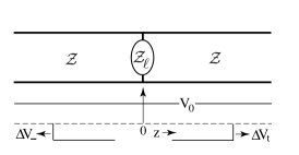
The standard conditions on the potential and current flow at () give and , where is the current flow through . In this way we find
| (15) |
Note that for , both and tend to zero.
The power loss rate in the load is
| (16) |
We assume that this power goes into accelerating charged particles which in turn produce the observed synchrotron radiation. This power could account for the emission of the E3 knot of 3C 303 (Kronberg et al. 2011) and, on parsec scales, the emission of the HST-1 knot in the M87 jet (Biretta et al. 1999).
The power is equal to the difference between the Poynting flux for ,
| (17) |
and the Poynting flux for ,
| (18) |
Using equation (17) we find that .
2.4 Magnetic Insulation
The Poynting jet is analogous to a magnetically insulated transmission line. In laboratory experiments magnetically insulated transmission lines involving crossed electric and magnetic fields are commonly used to transport pulses of high energy content onto small targets (e.g., Shope et al. 1978; Samokhin 2010). The condition for “magnetic insulation” of a planar gap of width between a conducting cathode and anode with potential drop and initially filled with a uniform magnetic field is , where V (Lovelace & Ott 1974; Ron, Mondelli, & Rostoker 1973).
In the astrophysical limit where , the condition for magnetic insulation is for the case where field components have the same radial dependence. If the power flow in the jet is unidirectional, as assumed in equations (2), then the condition for magnetic insulation is
| (19) |
where is a reference impedance. This inequality is always satisfied because the fields are time-independent and force-free ().
Consider now the case where the power flow is not unidirectional and where the fields are time and space-dependent, i.e., , . We assume so that To a first approximation the electric and magnetic fields correspond to those in a common transverse electric and magnetic (TEM) mode in a coaxial cable. Unlike a coaxial cable where the two conducting surfaces are separated by a dielectric, the Poynting jet has distributed charge and current densities. Because , the insulation condition can then be written as
| (20) |
where is a critical dimensionless number slightly larger than unity.
2.5 Consequences of Breakdown of Magnetic Insulation
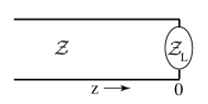
Here we discuss conditions where the magnetic insulation breaks down in a localized region near the termination of a Poynting jet due to a load which has an inductive component (Fig. 4.). An essential condition for this to occur is that the wave propagation not be unidirectional. The load is assumed to be stationary or sub-relativistic in the laboratory frame owing to the ram pressure from the external plasma. The breakdown of magnetic insulation in laboratory transmission lines is discussed by Gordeev (1978).
The consequences of the breakdown can be dramatic: Nuclei can be accelerated to energies of the order of eV while leptons may be accelerated to smaller energies owing to radiative losses and interactions with radiation. This value of the potential comes from the jet parameters deduced for 3C 303 with (Kronberg et al. 2011). (Note that magnetic insulation breakdown can also occur along the jet due to the reflected wave from a localized region of increased series inductance along the transmission line.)
The voltage across the Poynting jet, , is assumed to be made up of an incident component propagating along the jet channel with velocity and a reflected component with velocity . The corresponding jet current is . The spatial profile of the incident wave is considered to be a smooth rise to a constant value (taken to be unity) as shown in the top panel of Fig. 5. Such jet onsets are observed in the form of the sporadic formation of parsec-scale components of radio galaxies and quasars (e.g., Zensus et al. 1998). The onset may be explained by the global magnetic instability of the disc (Lovelace et al. 1994).
In such cases the wave amplitudes can be written as
| (21) |
with and with
| (22) |
where is in general frequency-dependent with real and imaginary parts. Figure 5 shows a case where is due to a resistance assumed equal to in series with and inductance . An estimate of is simply , where is the jet radius and is given by equation (9).
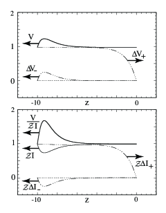
The top panel of Fig. 5 shows that there is a backward propagating positive voltage wave . The rise-time of the wave is equal to that of the incident wave while the decay-time is equal to the over time of the load. The voltage wave is positive because the inductance of the load appears initially to the incident wave as a high impedance. At the same time the reflected current is negative. The net voltage and current are such that there is a backward propagating wave with . This corresponds to a breakdown of the magnetic insulation.
The condition can exist only transiently (for a time ) because for the insulation breakdown will lead to a radial inflow of positive charge with speed and an opposite radial outflow of negative charge. At the same time both positive and negative charges drift in the direction with speed . This will bring the transmission line to the threshold condition where or .
Both positive and negative charged particles in the region where are accelerated in the direction which is approximately the direction. The acceleration is highly efficient in that a particle exposed to the wave for a time is accelerated to a Lorentz factor
| (23) |
which is much larger than unity. This formula is easily derived from the equations of motion. The electromagnetic energy in the backward propagating wave is dissipated into kinetic energy of the accelerated particles.
As a numerical example relevant to the HST-1 component in M87, we consider pc and mG (Harris et al. 2009) and assume that the jet consists of electrons and positrons. De Young (2006) discusses different models of extra-galactic jets involving plasmas dominated by electrons and positrons, electrons and ions, and electromagnetic fields (i.e., Poynting flux jets). For the electron-positron case,
| (24) |
where the time is normalized to s. The accelerated particles will in a time run into the region of the load where the magnetic field has a spread of directions. The time s is much longer than the dissipation time for the backward propagating wave. The synchrotron radiation peak from these high- leptons is at or a photon energy eV.
If the electromagnetic radiation of the source is entirely due to the accelerated particles, then , where is the number of accelerated leptons. Estimating and taking erg/s (Harris et al. 2009) gives the lepton number density . From this we obtain the so called ‘plasma beta’, . This implies that the load region of the jet is not force-free and that it will expand. Prior to the acceleration of the particles when the power flow in the jet is unidirectional, so that the jet is dominantly force-free. Synchrotron and other losses will give rise to a power law distribution of lepton energies with and with a cutoff at .
The estimated Lorentz factor (24) is larger than a critical value denoted set by the condition that the inverse Compton scattering of a lepton off a synchrotron photon (energy ), which gives an inverse Compton photon (energy ), be such that the subsequent scattering of the synchroton and secondary inverse Compton photons is above the threshold for electron-positron pair production []. This condition gives
| (25) |
where is the non-relativistic cyclotron frequency (e.g., Lovelace 1987). At this Lorentz factor, eV and eV.
The acceleration of particles is more complicated in the case of an electron-ion jet. The accelerated electrons will tend to increase more than the opposite effect from the ions. This will give rise to an inductive ambipolar field. It in turn retards the electron acceleration and enhances the ion acceleration. However, analysis of this problem is beyond the scope of the present work.
3 Conclusions
We have developed a model of Poynting jets as a transmission line carrying a net axial current and having a potential drop across it. The currents and voltages are of the order of A and V. The energy of ions accelerated across this voltage is large enough to account for ultra high energy cosmic rays (Lovelace 1976; Biermann et al. 2001; Ostrowski 2002). Further, we derive the transmission line impedance and the electromagnetic energy flow in the jet. The observed current in 3C 303 is used to independently estimate the electromagnetic energy flow in this magnetically dominated jet. Time-dependent but not necessarily small perturbations of a Poynting-flux jet - possibly triggered by an irregularity in the jet - are described by the “telegraphers’ equations,” which are wave equations for the current and voltage on the line. The voltage and current consist in general of forward and backward propagating components. The disturbance of a Poynting jet by an irregularity can give rise to localized dissipation in the jet which may explain the enhanced synchrotron radiation in the knots of the 3C 303 jet and in the much smaller apparently stationary knot HST-1.
Lastly, we consider relativistic Poynting jets relevant to parsec-scale jets such as HST-1. The reflected voltage wave from an inductive load (or jet termination) can lead to a backward propagating wave which causes the magnetic insulation to breakdown. That is, it gives . At the threshold for breakdown, , positive and negative particles are directly accelerated in the direction which is approximately along the jet axis. Particles can be accelerated up to Lorentz factors in a short time interval of the order of the light travel time across the jet. This particle acceleration mechanism is distinct from particle acceleration in shock waves and that in magnetic field reconnection.
The breakdown of magnetic insulation is not possible in a plasma that is modeled everywhere by ideal relativistic magnetohydrodynamics (RMHD). This is because the Ohm’s law of RMHD requires that everywhere. Of course an actual plasma can readily have . A common example is magnetic reconnection where there is a region in which the direction of the magnetic field reverses so that goes through zero on a surface. But even in regions of non-zero a plasma can have transiently as in pulse propagation along magnetically insulated transmission lines (e.g., Shope et al. 1978; Samokhin 2010). The restrictive Ohm’s law constraint of RMHD can be avoided in relativistic-electromagnetic particle-in-cell simulations where the orbits of individual particles are calculated (e.g., Lovelace, Gandhi, & Romanova 2005).f
An open question regarding the propagation of relativistic current-carrying Poynting jets is the kink instability. In the context of laboratory current-carrying plasmas, the kink instability is predicted and observed to occur if the current is larger than a critical value which is the Kruskal-Shafranov condition (e.g., Kadomtsev 1966; Huarte-Espinosa et al. 2012). The theory of the instability for relativistic Poynting jets has not been developed. Observational evidence for large current flows in astrophysical jets (e.g., Kronberg et al. 2011) suggest that the jets can withstand the kink instability. On the other hand a mechanism for the nonlinear stabilization of the kink instability was proposed by Kadomtsev (1966, p. 188).
Acknowledgments:
We thank D.E. Harris, G.S. Bisnovatyi-Kogan, S. Dyda, and M.M. Romanova for valuable discussions. Also, we thank the referee for valuable criticism. RVEL was supported in part by NASA grants NNX10AF-63G and NNX11AF33G and by NSF grant AST-1008636. PPK acknowledges support from NSERC Canada Discovery Grant A5713.
References
- [1] Asada, K., Inoue, M., Kameno, S., Fujisawa, K., Iguchi, S., & Mutoh, M. 2002, PASJ, 54, L39
- [2] Beckwith, K., Hawley, J.F., & Krolik, J.H. 2008, ApJ, 678, 1180
- [3] Benford, G. 1978, MNRAS, 183, 29
- [4] Bergeron, K.D. 1977, J. of Applied Phys., 48, 3065
- [5] Biermann, P.L., Kang, H., & Ryu, D. 2001, in ASP Conf. Series, V. 241, 57
- [6] Biretta, J.A., Sparks, W.B., & Macchetto, F. 1999, ApJ, 520, 621
- [7] Bisnovatyi-Kogan, G.S., & Lovelace, R.V.E. 1995, A&A, 296, L17
- [8] Blandford, R.D., & Znajek, R.L. 1977, MNRAS, 179, 433
- [9] De Young, D.S. 2006, ApJ, 648, 200
- [10] Gabuzda, D.C., Murray, E., & Cronin, P. 2004, MNRAS, 351, L89
- [11] Gordeev, A.V. 1978, Sov. Phys. Tech. Phys., 23, 463
- [12] Harris, D.E., Cheung, C.C., Stawarz, L., Biretta, J.A., & Perlman, E.S. 2009, ApJ, 699, 305
- [13] Heaviside, O. 1893, Electromagnetic Theory, (D. Van Nostrand: New York), p. 449
- [14] Huarte-Espinosa, M., Frank, A., Blackman, E.G., Ciardi, A., Hartigan, P., Lebedev, S.V., & Chittenden, J.P. 2012, ApJ, 757: id.=66
- [15] Kadomtsev, B.B. 1966, in Reviews of Plasma Physics, V. 2, pp. 153
- [16] Kronberg, P.P., Dufton, Q. W., Li, H., & Colgate, S. A. 2001, ApJ, 560, 178
- [17] Kronberg, P.P., Lovelace, R.V.E., Lapenta, G. & Colgate, S.A. 2011, ApJ, 741, L15
- [18] Lovelace, R.V.E. & Ott, E. 1974, Phys. of Fluids, 17, 1263
- [19] Lovelace, R.V.E. 1976, Nature, 262, 649
- [20] Lovelace, R.V.E. & Ruchti, C.B. 1983, in Positron-electron pairs in astrophysics, AIP Conf. Proc., 314
- [21] Lovelace, R.V.E. 1987, A&A, 173, 237
- [22] Lovelace, R.V.E., Wang, J.C.L., & Sulkanen, M.E. 1987, ApJ, 315, 504
- [23] Lovelace, R.V.E., Romanova, M.M., & Newman, W.I. 1994, ApJ, 437, 136
- [24] Lovelace, R.V.E., Li, H., Koldoba, A.V. , Ustyugova, G.V., & Romanova, M.M. 2002, ApJ, 572, 445
- [25] Lovelace, R.V.E., & Romanova, M.M. 2003, ApJ, 596, L162
- [26] Lovelace, R.V.E., Gandhi, P.R., & Romanova, M.M. 2005, Ap&SS 298, 115
- [27] Li, H., Lovelace, R.V.E., J. M. Finn, J.M., & Colgate, S.A. 2001, ApJ, 561, 915
- [28] Lynden-Bell, D. 1996, MNRAS, 279, 389
- [29] McKinney, R.D. 2006, MNRAS, 368, 1561
- [30] Nakamura, M., Tregillis, I.L., Li, H., & Li, S. 2008, ApJ, 686, 843
- [31] Ostrowski, M. 2002, Astroparticle Physics 18, 229
- [32] Ron, A., Mondelll, A.A., & Rostoker, N. 1973, IEEE Trans. Plasma Sci. PS-l, 85
- [33] Samokhin, A.A. 2010, Plasma Phys. Reports, 36, 682
- [34] Shope, S., Poukey, J.W., Bergeron, K.D., MacDaniel, D.H. Toepffer, A.J., & Vandevender, J.P. 1978, J. of Applied Phys., 49, 3675
- [35] Tchekhovskoy, A., Narayan, R., & McKinney, J.C. 2011, MNRAS, 418, L79
- [36] Ustyugova, G.V., Lovelace, R.V.E., Romanova, M.M., Li, H., & Colgate, S.A. 2000, ApJ, 541, L21
- [37] Zavala, R.T., & Taylor, G.B. 2005, ApJ, 626, L73
- [38] Zensus, J.A., Taylor, G.B., & Wrobel, J.M. (eds.) 1998, Radio Emisssion from Galactic and Extragalactic Compact Sources, IAU Colloquium 164, (Astronomical Society of the Pacific: San Francisco)
Appendix A Waveguide Model of Poynting Jet
There are a wide range of axisymmetric, translationally-symmetric, time-independent Poynting jet models which satisfy the relativistic, force-free equation,
| (26) |
(cgs units). This assumes that there is plasma everywhere, but that the ‘plasma beta’ - the ratio of the kinetic energy-density to electromagnetic field energy-density is . The time-independence of the solutions of (A1) implies that the energy flow in the jet is unidirectional. Here, we assume this is the direction. Realistic models can in principle be derived for example from relativistic particle-in-cell simulations (e.g., Lovelace et al. 2005). Here, we discuss a waveguide-like jet model alternative to that considered in the text. The electric and magnetic fields are similar to the fields in a TEM coaxial waveguide. This model is suggested by the work of Bisnovatyi-Kogan & Lovelace (1995).
Equation (A1) is satisfied by the fields shown in Fig. A1. For , the magnetic field is const and the electric field is zero. For , the magnetic field is , and the electric field is where , and const is dimensionless (cgs units). For , the magnetic field is and the electric field is zero. The condition on the magnetic field at is the same as discussed in the text. The plasma in the region has a uniform axial drift velocity or Lorentz factor . This model involves only a small number of parameters, .
In MKS units, the current carried by the core of the jet (in A) is . Thus the poloidal flux carried by the jet is
| (27) |
The voltage drop across the jet is
| (28) |
where
| (29) |
This formula is the counterpart of equation (4). The electromagnetic power flow in the Poynting jet is
| (30) |
which agrees with the equation (3).
The electric field energy per unit length is
| (31) |
where
| (32) |
is the capacitance per unit length of the jet.
The magnetic energy per unit length of the jet is
| (33) | |||||
Carrying out the integrals we find
| (34) |
which is the inductance per unit length of the jet.
From equations (A7) and (A9) we find the wave speed on the jet is
| (35) |
The wave impedance of the transmission line is
| (36) |
Equations (A10) and (A11) are the analogues of equations (12) and (14).