Forced generation of simple and double emulsions in all-aqueous system
Abstract
We report an easy-to-implement method that allows the direct generation of water-in-water (w/w) single emulsions. The method relies on direct perturbation of the pressure that drives the flow of the dispersed phase of the emulsions. The resultant inner jet is induced to break up into droplets due to the growth of the perturbation through Rayleigh-Plateau instability [L. Rayleigh, Proc. R. Soc. London 29, 71 97 (1879)]; this leads to the formation of monodisperse droplets. By implementing this method on a modi ed microfluidic device, we directly generate water-in-water-in-water (w/w/w) double emulsions with good control over the size and the number of encapsulated droplets. Our approach suggests a new route to apply droplet-based microfluidics to completely water-based systems.
Recent advances in the generation of emulsion drops have led to applications in various fields such as food industry, cosmetics, drug delivery, and oil extraction.stone2004 ; squire2005 ; basaran2002 ; gunther2006 ; muschiolik2007 The ability to generate single and multiple emulsions with controlled morphology has been used for fabricating a variety of functional materials including microgels, liposomes, polymersomes, and colloidosomes.kim2007b ; shah2008 ; shum2008 ; shum2011a ; lee2009b
However, the ability of producing monodisperse emulsions in some systems such as aqueous two-phase systems (ATPS), where the two aqueous phases have different properties, such as density, viscosity, and refractive index, is challenged by their low interfacial tensions.hardt2012 The tension for ATPS is typically less than mN m-1,ziemecka2011 preventing the breakup of the jet.shum2010 An approach to induce droplet formation in these systems is to apply an external forcing to the flow at a given frequency. The resulting perturbation can induce the breakup of the jet into droplets through Rayleigh-Plateau instability.plateau1849 ; rayleigh1879 ; eggers2008 This has been accomplished through the use of an electric field in a flow-focusing microfluidic device,kim2007 piezoelectric actuatorziemecka2011 or multi-level rounded channels.lai2011 However, these methods are not always simple to implement on a microfluidic device, for instance, when electric fields cannot be used or when the device material does not allow straightforward incorporation of the functional components needed.utada2005
In this Letter, we report a method to directly generate water-in-water (w/w) emulsions and water-in-water-in-water (w/w/w) double emulsions in glass microcapillary devices. To achieve this, we perturb the pressure that drives the flow of the dispersed phase in a controlled manner, disrupting the jet periodically. This results in monodisperse droplets whose size can be tuned. By implementing this approach on a modified microfluidic device, we directly generate w/w/w double emulsions with good control over their size and the number of encapsulated droplets.
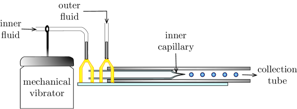
The experimental setup is made up of two coaxially aligned capillary tubes. A cylindrical inner capillary, with an approximate tip diameter of , is coaxially inserted in a square outer capillary, with an inner dimension of . Two flexible tubings bring the inner and outer fluids in the capillaries at the flow rates and respectively. The inner phase is an aqueous solution of polyethylene glycol (PEG, MW=8000, wt) and the outer phase is an aqueous solution of dextran (T-500, MW=500 000, wt). The interfacial tension between the two phases is low, about mN m-1.ziemecka2011 We connect a mechanical vibrator (PASCO Model SF-9324) to the tubing for injecting the inner fluid. The vibrator is controlled by an external generator for tuning the frequency in the range with a sinusoidal variation. Vibration of the tip of the inner capillary was not observed; the effect induced by the mechanical vibrator is only due to variation of pressure at the imposed frequency. This method enables precise control of the frequency of the pressure perturbation, which is key to the production of droplets with good control over droplet sizes. The experimental setup is shown in figure 1.
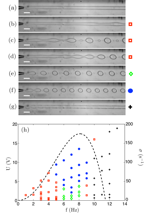
To generate w/w emulsions, the dispersed phase is injected through a plastic flexible tubing connected to the mechanical vibrator, which oscillates at a specific frequency and induces pressure perturbation in the dispersed phase. The continuous phase flows through the square capillary. For a typical set of fluid flow rates of the dispersed phase and without perturbation, a jet exiting the inner capillary does not break up into droplets, as shown in figure 2(a).shum2012 At the flow rates, and , a stable jet is visible and no droplet formation occurs. For a given input voltage, a low perturbation frequency leads to the formation of a wavy interface with a well defined wavelength between the two fluids, as shown in figure 2(b) where a frequency of Hz is applied. The wavelength visible at the interface is directly linked to the frequency of excitation for given inner and outer fluid flow rates and thickness of the inner jet by the relation and the velocity of the fluid of the inner jet is given by . However, the jet does not break up into droplets at this frequency except sporadically and very far from the nozzle. As the frequency of perturbation is increased to Hz, the jet starts to break up into droplets near the inner capillary nozzle with satellite droplets connecting the larger droplets (figure 2(c)). At slightly higher frequency of Hz, the jet directly breaks up into droplets with no visible satellites droplets (figure 2(d)). When the frequency reaches Hz, monodisperse droplets with smaller satellite droplets form by dripping at the capillary tip (figure 2(e)). At an optimized frequency, f=8 Hz in this case, monodisperse droplets are induced in a dripping regime (figure 2(f)). If the frequency of perturbation becomes larger than a critical value, which is f=10 Hz in the present case, the growth rate becomes zero. Therefore, the perturbations visible in the part of the jet near the nozzle are quickly smoothed out as the jet flows downstream (figure 2(g)). Based on our systematic investigation of the effects of perturbation frequency and input voltage on the flow regimes, monodisperse droplets formed directly at the tip of the inner capillary can be achieved only for a sufficiently high input voltage (typically more than V) and a small range of frequency ( Hz). Under these conditions, the growth rate of the Rayleigh-Plateau instabilityguillot2007 is maximized at Hz (black dotted line in figure 2(h)). At low applied perturbation frequency, Hz, the droplets are formed at some distance from the tip of the inner capillary. Due to the slow rate of growth of the perturbation, the time and thus the distance from the tip to the point at which the jet breaks up become very large. At high frequency Hz, no droplets are produced. The inability to generate droplets is predicted by the Plateau criterion for the breakup of the jet, which states that when the wavelength of the perturbation is smaller than the circumference of the jet, i.e., for , no perturbation can grow and thus the jet does not break up. In terms of frequency of perturbation, it leads to the inequality Hz.eggers2008 The amplitude of pressure perturbation is tightly related to the amplitude of the shaking of the inner tubing, which is tuned by varying the input voltage of the vibrator. For a given input voltage V, droplets are formed directly at the tip of the inner capillary only for Hz. However, as the input voltage is increased up to V, the range of frequency for generation of droplets is increased to Hz. However, the exact relationship between the amplitude of pressure perturbation and that of shaking in an oscillating flexible tube remains challenging.whittaker2010 A state diagram summarizing the morphologies at different perturbation frequencies and input voltages is presented in figure 2(h).
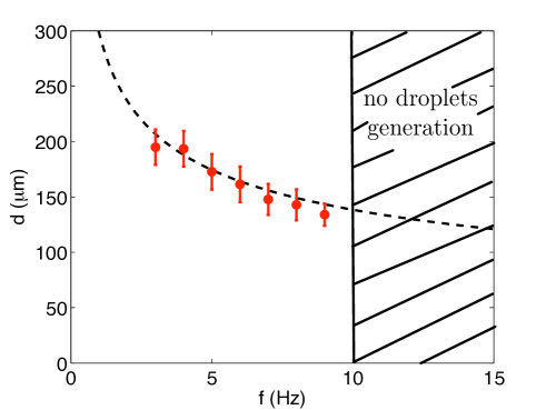
The present experimental approach also enables control over the size of the emulsion drops. When induced by perturbation, the jet is forced to break up at a wavelength imposed by the frequency of applied perturbation. The volume of one droplet of diameter is calculated as . As the frequency of the droplet formation matches the perturbation frequency , the volume of the jet that contributes to one droplet is . The flow rate of the dispersed phase is defined as . Mass conservation implies that the volume and are equal. Therefore, the diameter of one droplet scales as .utada2007 This expression is in excellent agreement with the experimental measurements shown in figure 3.
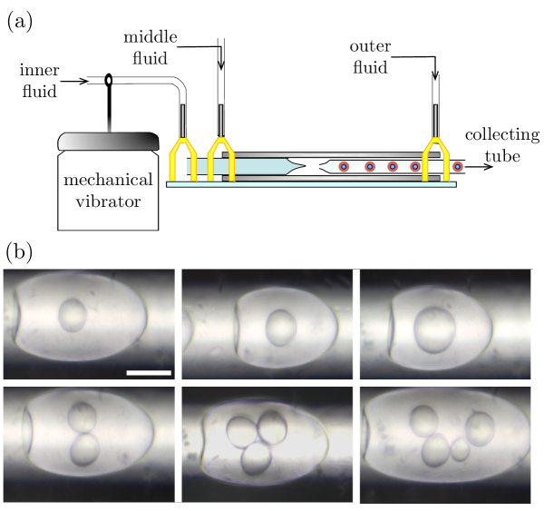
A further challenge in materials engineering, apart from generation of monodisperse w/w emulsions is the preparation of w/w/w double emulsions. All-aqueous core-shell droplets have recently been generated through a process of spontaneous phase separation.ziemecka2011b Unlike in classical droplet microfluidic approaches, where the species to be encapsulated are separated from the continuous phase by a middle shell phase, undirected emulsification processes likely lead to limited efficiency when applied to encapsulate cells or other active ingredients in a given phase. Our approach for fabricating controlled w/w emulsions can be adapted for the formation of w/w/w double emulsion using a modified glass microcapillary deviceutada2005 (see figure 4(a)). In this case, aqueous PEG solution forms the middle phase while aqueous dextran solution forms both the inner and outer phases. The mechanical vibrator is connected to the inner plastic tubing as in the formation of simple w/w emulsion. The formation of the inner droplets within the middle phase helps modify the shape of the middle/outer interface, as shown previously in a multiphase flow with low interfacial tension.shum2010 Consequently, this facilitates the breakage of the middle jet into droplets. By tuning the outer fluid flow rate, we can match the breakup frequency of the middle jet to that of the inner droplets. Thus, droplets containing fixed number of inner droplets, that is, w/w/w double emulsion, are achieved. Tuning the frequency and the input voltage as well as the flow rates of both phases lead to a good control over the size of the inner droplets and the number of the inner droplets encapsulated in the middle fluid (see figure 4(b)).
In this Letter, we report a new approach that enables the generation of monodisperse all-aqueous single and double emulsions. This is achieved by inducing a variation of pressure of the dispersed phase. Our approach is easy to implement, low-cost and allows a good control over the flow morphologies. Moreover, we also demonstrate the first direct generation of w/w/w double emulsion. The resulting emulsions are not stabilized by any surface-active agents and destabilize through coalescence upon contact with neighboring droplets. These unconventional emulsions are not easily stabilized by conventional amphiphilic agents. While we illustrate the concept using capillary microfluidics, the understanding acquired is applicable to other microfluidic approaches, such as two-dimensional poly(dimethyl siloxane)-based microfluidics. The ability to generate single and double emulsions in an all-aqueous environment in the absence of any organic solvent creates important opportunities to fabricate completely biocompatible materials with low environmental risks using droplet microfluidics. With this approach, the established methods for oil-water-based emulsion can be adapted to all-aqueous emulsions, which have great potential for biomedical, pharmaceuticals, food and cosmetics application that require high degree of biocompatibility.
We gratefully acknowledge financial support from the Seed Funding Programme for Basic Research from the University of Hong Kong (201101159009).
References
- (1) H. A. Stone, A. D. Stroock, and A. Ajdari, Ann. Rev. Fluid Mech 36, 381 (2004).
- (2) T. M. Squire and S. R. Quake, Rev. Mod. Phys. 77, 977 (2005).
- (3) O. A. Basaran, AIChE J. 48, 1842 (2002).
- (4) A. Gunther and K. F. Jensen, Lab Chip 6, 1487 (2006).
- (5) G. Muschiolik, Curr. Opin. Colloid Interface Sci. 12, 213 (2007).
- (6) J.-W. Kim, A. S. Utada, A. Fernandez-Nieves, Z. Hu, and D. A. Weitz, Angew. Chem., Int. Ed. 46, 1819 (2007).
- (7) R. K. Shah, H. C. Shum, A. C. Rowat, D. Lee, J. J. Agresti, A. S. Utada, L. Y. Chu, J. Kim, A. Fernandez-Nieves, C. J. Martinez, and D. A. Weitz, Mater. Today 11, 18 (2008).
- (8) H. C. Shum, D. Lee, I. Yoon, T. Kodger, and D. A. Weitz, Langmuir 24, 7651 (2008).
- (9) H. C. Shum, Y. J. Zhao, S. H. Kim, and D. A. Weitz, Angew. Chem., Int. Ed. 50(7), 1648 (2011).
- (10) D. Lee and D. A. Weitz, Small. 5, 1932 (2009).
- (11) S. Hardt and T. Hahn, Lab Chip 12, 434 (2012).
- (12) I. Ziemecka, V. van Steijn, G. J. M. Koper, M. Rosso, A. M. Brizard, J. H. van Esch, and M. T. Kreutzer, Lab Chip 11, 620 (2011).
- (13) H. C. Shum, A. Sauret, A. Fernandez-Nieves, H. A. Stone, and D. A. Weitz, Phys. Fluids 22(8), 082002 (2010).
- (14) J. Plateau, Acad. Sci. Bruxelles Mem. 23, 5 (1849).
- (15) L. Rayleigh, Proc. R. Soc. London 29, 71 97 (1879).
- (16) J. Eggers and E. Villermaux, Rep. Prog. Phys. 71, 036601 (2008).
- (17) H. Kim, D. Luo, D. Link, D. A. Weitz, M. Marquez, and Z. Cheng, Appl. Phys. Lett. 91, 133106 (2007).
- (18) D. Lai, J. P. Frampton, H. Sriram, and S. Takayama, Lab Chip 20, 3551 (2011).
- (19) A. S. Utada, E. Lorenceau, D. R. Link, P. D. Kaplan, H. A. Stone, and D. A. Weitz, Science 308, 537 (2005).
- (20) H. C. Shum, J. Varnell, and D. A. Weitz, Biomicro uidics 6, 012808 (2012).
- (21) P. Guillot, A. Colin, A. S. Utada, and A. Ajdari, Phys. Rev. Lett. 99, 104502 (2007).
- (22) R. J. Whittaker, S. L. Waters, O. E. Jensen, J. Boyle, and M. Heil, J. Fluid Mech. 648, 83 (2010).
- (23) A. S. Utada, A. Fernandez-Nieves, H. A. Stone, and D. A. Weitz, Phys. Rev. Lett. 99, 094502 (2007).
- (24) I. Ziemecka, V. van Steijn, G. J. M. Koper, M. T. Kreutzer, and J. H. van Esch, Soft Matter 7, 9878 (2011).