Effect of confinement on dense packings of rigid frictionless spheres and polyhedra
Abstract
We study numerically the influence of confinement on the solid fraction and on the structure of three-dimensional random close packed (RCP) granular materials subject to gravity. The effects of grain shape (spherical or polyhedral), material polydispersity and confining wall friction on this dependence are investigated. In agreement with a simple geometrical model, the solid fraction is found to decrease linearly for increasing confinement no matter the grain shape. Furthermore, this decrease remains valid for bidisperse sphere packings although the gradient seems to reduce significantly when the proportion of small particles reaches by volume. The confinement effect on the coordination number is also captured by an extension of the aforementioned model.
pacs:
45.70.-sn \sep45.70.Cc \sep61.43.-jI Introduction
Granular materials are well known for their wide range of fascinating properties. Their theoretical description is difficult for many reasons. One of them is the importance of the local arrangement of grains within the material on its macroscopic behavior.
Real granular systems have boundaries, but for the sake of simplicity, scientists often neglect them (see for example Silbert_PRE_2002 ; Agnolin_PRE_2007 ) and the system is then considered as infinite.
This assumption is not always justified since the presence of boundaries modifies the system local arrangement in their vicinity. Moreover, due to the intrinsic steric hindrance of granular materials those structure modifications often propagate over distances in the order of several grain sizes. As a consequence, the behavior of granular systems may be strongly influenced by the presence of sidewalls even if the confinement length is large compared to the grain size.
The crucial role of confinement on system properties has been pointed out in many works dealing with gravity driven granular flows Taberlet2003 ; Taberlet2004b ; Jop2005 ; Taberlet2006b ; Richard2008 ; Taberlet2008 , granular segregation Peirera2011 , structure and mechanics of granular packings BenAim1968 ; Suzuki2008 ; Landry2003 , granular systems in narrow silos Landry_powdertech_2004 or granular penetration by impact Seguin2008 .
Those studies point out that two major physical properties can be influenced by the presence of sidewalls. First, they can induce friction that might be important in respect to the internal friction of the system Richard2008 explaining the well-know Janssen effect Vanel2000 or unexpectedly high angle values observed with confined granular heaps Liu1991 ; Courrech2003 or confined chute flows Taberlet2003 . Second, as mentioned above, they might also alter the geometrical structure of the system near the wall, where
particles tend to form layers, giving rise to a fluctuating local solid fraction with distance from the wall Suzuki2008 and affecting the properties of confined systems.
Note that the effect of confinement is not limited to the vicinity of the walls but may propagate within the sample. This is more particularly the case for confined granular chute flows for which it has been shown that the good dimensionless number to quantify the sidewall effect is not the number of grains per unit of width between sidewalls but the ratio of the flow height to the gap between sidewalls Taberlet2003 .
Here, we focus mainly on the geometric effect of the presence of sidewalls on quantities like the solid fraction and the coordination numbers.
Recently, Desmond and Weeks used numerical simulations to study the effect of confinement on binary atomic systems at the random-close-packing limit Desmond2009 .
Their numerical results agree with a simple geometrical model Verman_Nature_1946 ; Brown_Nature_1946 ; Combe_PhD_2001 (hereafter called the geometrical model) which captures the evolution of the solid fraction of random close packings of spheres with confinement. It is based on the following configuration: a packing of particles is confined between two parallel and flat walls separated by a gap . It then assumes that such a confined system is made of two boundary layers (of thickness ) and a bulk region and that the solid fraction of the boundary layers, , is lower than that of the bulk region .
By writing the total solid fraction as the average of both the bulk region and boundary layers solid fractions (weighted by their relative thickness), the geometrical model predicts that the average solid fraction decreases linearly with :
| (1) |
where . Note that this model can be easily adapted to other boundaries such as cylindrical ones Desmond2009 . The three parameters of the geometrical model (, and ) probably depend on grain shape, packing polydispersity and confining wall properties.
Here we study the effect of confinement on quasi-static dense frictionless granular systems (i.e. grains interacting through hard core repulsion)
subjected to gravity. We test the validity of the geometrical model for such systems and study the aforementioned dependencies. Using numerical simulations, we investigate the actual effect of grain shape by comparing packings of spheres with packings of polyhedra. Furthermore, we assess the effect of packing polydispersity by comparing monosized and binary packings. Besides, we check the effect of grain-wall friction.
Eventually, we look into packing microstructure by studying the effect of confinement on the coordination number.
The paper is organized as follows. Section II describes our simulations with details as well as the numerical simulation method used. After checking the state of packings in section III, section IV investigates how the solid fraction is modified by confinement and how these modifications are influenced by packing polydispersity, grain shape and confining wall friction. Then, we examine in section V the modification of the packing microstructure with confinement. Finally, in section VI we summarize our results and present our conclusions.
II Simulation methodology
II.1 Geometry of grains
The simulated system is a three-dimensional dense assembly of frictionless rigid grains of mass density , interacting with each other through totally inelastic collisions.
Since grain shape may influence the behavior of granular materials Atman_JPCM_2005 ; Ribiere2005 ; Ribiere2005c ; Szarf2011 , two types of grains have been studied: spherical grains of average diameter and polyhedra of average characteristic dimension . The polyhedra shape (Fig. 1) is that of a pinacoid, with eight vertices, fourteen edges and eight faces. This polyhedron has three symmetry planes and is determined by four parameters: length , width , height and angle . According to an extensive experimental study with various rock types reported by Tourenq82 , the pinacoid gives the best fit among simple geometries for an aggregate grain. In order to have similar aspect ratio for both grain shapes, the pinacoid dimensional parameters were taken identical (), with the characteristic dimension expressed as . In addition, angle was set to . For each grain shape, two grain diameters (or characteristic dimensions) have been considered: large and small .

II.2 Samples preparation
The packing geometry is that of a parallelepiped (Fig. 2) of dimensions by by . Periodic Boundary Conditions (PBC) are applied in the direction to simulate an infinitely long parallelepiped using a finite number of grains. The packing is confined in the direction between two fixed parallel walls separated from each other by a large gap.
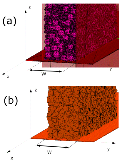
In some cases, PBC are also applied along the axis to simulate unconfined reference state, with set to . The packing is supported on the -plane by a fixed frictionless bottom wall and delimited by a free surface at its top.
Grain samples are composed of various proportions of small and large grains having the same shape. In order to reduce the thickness of the crystallized layer commonly observed inside confined packings at the interface with smooth walls murray_98 ; Teng_PRL_2003 , each population of grain size is randomly generated with a Gaussian distribution characterized by its mean and its variance . Anyhow, for the sake of simplicity, packings made of a unique population of grains (either small or large) will be called ”monodisperse”, whereas packings made of small and large grains will be called ”bidisperse” in the following. In the latter case, the proportions of small () and large () grains expressed as percentages by volume are of course linked through .
Each sample is constructed layer-by-layer according to the following geometrical deposition protocol inspired by Laniel_PhD_2007 : spherical particles of a sufficient diameter to circumscribe the larger grains of the sample are sequentially dropped along in a parallelepiped box having the aforementioned geometry. Each particle stops on the free surface made of the underneath layer of particles (or on the bottom wall for the first layer of particles) and is further moved so that it lays on three particles chosen to locally minimize its altitude . Finally, the sample actual grains are randomly substituted for those spherical particles. For polyhedra samples, a random orientation is further assigned to each pinacoid. Note that according to this protocol, some of the deposited grains may not be in contact with their neighbors depending on their size and shape.
II.3 Initialization and solicitations
The system initialization is identical for spheres and pinacoids samples. The first step consists in geometrically depositing grains into a parallelepiped box, then PBC are substituted for the lateral walls of the parallelepiped box along the direction (along the and directions for biperiodic reference state). Finally, gravity (,,) is applied in order to compact the sample.
II.4 Contact dynamics method
Discrete numerical simulations were performed using the contact dynamics (CD) method Moreau94 ; Moreau96 , which is specially convenient for rigid grains. This method is based on implicit time integration of the equations of motion with respect to generalized non-smooth contact laws describing non-interpenetration and dry friction between grains. This formulation unifies the description of lasting contacts and collisions through the concept of impulse, which can be defined as the time integral of a force. The generalized non-smooth contact laws are expressed in terms of impulse and formal relative velocity at contact point C. If , , and denote the normal and tangential relative velocities at contact point respectively before and after collision, the formal normal and tangential relative velocities are defined as follows:
| (5) |
where and measure the inelasticity of collisions and reduce to the normal and tangential restitution coefficients in the case of binary collisions.
These generalized contact laws support momentum propagation through contact networks inherent to dense assemblies of grains. For a given time step, impulses and velocities are determined according to an iterative process using a non-linear Gauss-Seidel like method Jean99 . In the case of large size packings of rigid grains, the CD method supports larger time steps, leading potentially to faster calculations than the molecular dynamic method for which small time steps are needed.
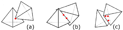
The CD method was applied using the LMGC90© platform Dubois03 ; Radjai11 which namely implements a 3D extension of a 2D contact detection algorithm described with details in Azema_PRE_2007 . Basically, contacts with a given grain are sought exclusively among its neighbors. When a neighbor is located closer to the grain than a threshold distance called gap, a 3D extension of the shadow-overlap method devised by Moreau Saussine06 ; Dubois03 is applied. In case of overlap between the grain shades, their contact plane is determined. Four contact situations may be encountered (Fig. 3): vertex-to-face or edge-to-edge, represented by a single point and called simple; edge-to-face, represented by two points and called double; finally, face-to-face, represented by three points and called triple (vertex-to-edge and vertex-to-vertex being very unlikely to happen). These situations allow identifying a contact plane and compute the contact impulse and velocity components at each contact point.
This method proved apt to deal with dense flows of disks Chevoir01a ; Lois_PRE_2005 ; Lois_EPL_2006 as well as with quasi-static plastic deformation Azema_PRE_2006 ; Azema_PRE_2007 ; Estrada_PRE_2008 ; Azema_EPJE_2008 ; Azema_MechMat_2009 ; Azema_PRE_2010 .
II.5 Materials and system parameters
The present study focuses on monodisperse sphere packings (MSP), bidisperse sphere packings (BSP) and monodisperse pinacoid packings (MPP).
The spacing of lateral walls takes discrete values between and , and the sample period along the axis is . With the final height of the packing in the range of to , the number of grains varies between 1,900 and 30,400 for spheres, depending on the proportion by volume of small grains, and between 3,600 and 15,000 for pinacoids.
The time step value is taken small enough to moderate the grain interpenetration incumbent to grains displacement between two successive implementations of the contact detection algorithm, but sufficiently large to keep the calculation duration reasonable. In this perspective, limiting to the translation of grains during seems appropriate. For our grain packings subject to compaction under their own weight, this leads to the following relation:
| (6) |
with the maximum speed reached by a grain free falling from initial height of the deposited packing down to the altitude of the packing free surface at the end of the compaction. Hence, equation 6 leads to the following expression for the time step:
| (7) |
Although the between-grain friction is set to zero, that of wall-grain contacts () is assigned non-zero values in a few simulations to study the influence of wall friction.
The simulated system parameters are summarized in table 1 for spheres and in table 2 for pinacoids. They are expressed as dimensionless quantities by defining the following normalization terms: lengths and times are respectively measured in units of and , the characteristic free fall time of a rigid grain of diameter subject to gravity exclusively. For a given set of system parameters, three grain packings are simulated in order to average the various measured quantities.
| , | |||||||
|---|---|---|---|---|---|---|---|
| , | ||||||
|---|---|---|---|---|---|---|
III State of packings
In order to examine the influence of wall-induced confinement on the solid fraction and structure of dense packings for various grain shape and polydispersity, it is necessary to adopt a reference packing state and to ensure that the compaction method used allows to approximate such a state while providing sufficient repeatability for a given set of materials and system parameters. As mentioned in paragraph II.3, the compaction method used consists in depositing rigid frictionless grains (with or without wall friction) under their own weight. For sphere packings with presumably negligible confinement, several authors have experimentally macrae_61 ; emam_05 or numerically Zhang2001 ; Silbert_PRE_2002 ; emam_05 observed that this compaction method led to random close-packed states characterized by the generally agreed solid fraction value of . According to roux_04 , random close-packed states of rigid frictionless grains (spherical or non-spherical) are equivalent to packing states in which the grains are homogeneously spread and in a stable equilibrium without crystallization or segregation (observe that the notion of ”stable equilibrium” refers to the minimization of a potential energy that ensures maximum solid fraction Roux_PRE_2000 ). Furthermore, extensive investigation of the random close-packed state carried out by Agnolin_PRE_2007 with spherical particles has evidenced the uniqueness of this state in the limit of infinitely large samples subject to fast isotropic compression (to avoid cristallization). Hence, the influence of wall-induced confinement on the solid fraction and structure of dense packings may be assessed against the random close-packed state taken as the reference. Keeping in mind that our compaction method only allows to approximate the random close-packed state (our compression is not isotropic) and that the uniqueness of this reference state has only been evidenced for sphere packings, it is expected that meeting as much as possible the criteria stated by roux_04 will lead to sufficiently repeatable solid fraction and microstructure characteristics for a given set of materials and system parameters to observe confinement effects for various grain shapes and polydispersity. Therefore, preliminary assessment consists in checking the state of our simulated packings (both sphere and pinacoid packings) in terms of stable equilibrium, homogeneity and reasonable interpenetration given the particularities of the contact dynamics method. Further assessment will be undertaken in sections IV and V.
III.1 Equilibrium
According to Agnolin_PRE_2007 , grain packings for which the following criteria are met on each grain have reached a stable equilibrium:
| (8) |
| (9) |
| (10) |
where , and are respectively the net force, net momentum and total kinetic energy of the grain. Indeed, Agnolin_PRE_2007 have observed that setting to zero all grain velocities in such a state and letting the packing relax further did not lead to any kinetic energy or unbalanced force level regain beyond these threshold values.
As a consequence, these criteria were used to check the attainment of a stable equilibrium state in our simulations, which was the case for all of them.
III.2 Interpenetration
The grain interpenetration, calculated as the sum of interpenetrated volumes between neighboring grains divided by the sum of grain volumes, was checked in the bulk region of the packing at the end of each simulation.
For sphere packings, the interpenetration was calculated analytically as the sum of interpenetrated volumes between couples of spheres (for a given couple of spheres, the interpenetrated zone consists of two spherical caps) and it was found to be very low (in the range of to by volume).
For pinacoids, a routine was designed to compute the solid fraction as well as lower and upper bounds of the grain interpenetration. Basically, this routine consists of superimposing a lattice on the grain packing and calculating the solid volume in each cell of the lattice. For a given cell, this solid volume is the sum of elementary volumes analytically calculated from the intersection between any pinacoid and the cell.
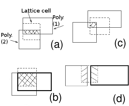
In order to bound the grain interpenetration, one shall focus on cells intersected by two neighboring pinacoids, leading to one of the four situations depicted on Fig. 4 (in 2D for simplicity reasons):
-
•
In situations and , the solid volume contained by the cell is in excess of actual cell volume , hence the lower bound of actual interpenetrated volume is (situation ) whereas the upper bound is (situation );
-
•
In situations and , the solid volume contained by the cell is smaller than actual cell volume, hence the lower bound of actual interpenetrated volume is (situation ) whereas the upper bound is (situation ).
Observe that is the upper bound of the interpenetrated volume no matter the situation. When their size decrease, the lattice cells that are intersected by two pinacoids tend to concentrate exclusively inside actual interpenetrated areas () where or astride their border () where . Hence, the total interpenetrated volume of the packing is bounded by the following interval:
,
in which tends to zero with decreasing cell size.
For each pinacoid packing geometry, table 3 gathers lower and upper bounds of grain interpenetration, e.g bounds of expressed as a percentage of the packing solid volume. These values were computed in the bulk region using a lattice with -large cubical cells, and each of them was averaged over three simulations. The interpenetration calculated in our pinacoid packings, in the range of 3 to 5% by volume, is clearly much higher than the one calculated for sphere packings.
| (% vol.) | ||||
| (% vol.) |
A first reason to explain these differences lies with the determination of contact between two grains. In the case of sphere packings, this determination is very simple and requires no interpenetration: grains are in contact when the distance between their centers is lower or equal to the sum of their radii. Such a contact is only one point, which is located on the segment connecting the centers of spheres at a distance of each sphere center equal to its radius. Besides, the orientation of the contact normal is borne by the segment connecting the grain centers. In the case of pinacoid packings, the determination of contact between two grains is much more complex, time-consuming and implies more or less interpenetration: first, grains are in contact when their respective shadows always overlap no matter the projection direction. Hence, much more calculation than for sphere packings shall be performed to prove the existence of a contact, and the simultaneous achievement of these overlap situations generally implies some interpenetration. Next, in case of a contact, it may not be a unique point but rather two (edge-to-face contact) or three (face-to-face contact) points as explained in section II.4, which obviously leads to more interpenetration.
A second reason lies with the non-smooth approach associated with the contact dynamics. In molecular dynamics Frenkel2001 , contact forces increase proportionally to a power function of the interpenetration, leading to high repulsion contact forces thus low interpenetration in the limit of rigid grains. In the contact dynamics method where no such relation is applicable, the interpenetration is namely monitored by the quality of the convergence of impulses and velocities at contact points within the range of permissible values on the generalized non-smooth contact laws. Hence, in addition to an appropriate time step value, a low level of interpenetration requires optimizing both the convergence criteria and number of Gauss-Seidel iterations while keeping the calculation time acceptable (for more information, refer to Moreau94 ; Moreau96 ; Dubois03 ; Radjai11 ).
Anyhow, the contact dynamics method is known to give interpenetration values in the order of a few percent by volume (see Saussine_04 ), and our quest of the densest possible disordered packing made of frictionless particles unsurprisingly leads to interpenetration values in the higher range. Hence the interpenetration evidenced by our results is acceptable.
III.3 Homogeneity of distribution
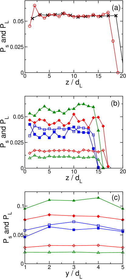
In order to ensure that the applied compaction method leads to homogeneously distributed packings, we examine the variations in the proportions of large () and small () grains with distance from the bottom wall (Fig. 5 (a) and (b)). Therefore we count the number of particles of each size in -thick regions of the packing and divide that number by the total number of grains. Although small deviations (that may be due to segregation) close to the bottom of our packings are observed, the proportion profiles are almost constant showing that grains in sphere or pinacoid packings are reasonably vertically homogeneously distributed. The absence of segregation along the axis is also checked for BSP in the homogeneous zone (e.g. far from bottom and free surface). Fig. 5 (c) displays the variations of proportions and in -thick layers parallel to the sidewalls. The proportion profiles are almost constant, showing reasonable horizontal homogeneity.
IV Solid fraction
IV.1 Average solid fraction
In this subsection, our aim is to study the effect of confinement on the solid fraction of MSP, BSP and MPP, that is to say for various proportions of small particles and various grain shapes. For this purpose, we report the evolution of the aforementioned quantity for several values of gap between sidewalls. We will also test the geometrical model mentioned in the introduction (cf Eq. 1). The solid fraction is computed from analytical calculation of the volume of each sphere or each pinacoid present within a given volume. This volume incorporates any particle located away from the bottom wall and the free surface. For the solid fraction of sphere packings, the use of the Voronoï tessellation Richard1999 ; Richard_EPJE_2001 gives the same results.
Figure 6 reports the average solid fraction for BSP, MSP and MPP versus . A first observation is that for a fixed value, an addition of small grains in a monosized sphere packing increases the solid fraction. This well-known phenomenon can easily be understood by considering two limit cases. The first one consists of a monosized sphere packing to which we add a few small particles (). In this case, small grains partially fill the porosity of the monosized packing and increase the solid fraction. The second limit case corresponds to a packing of small grains to which we add a few large particles (). The largest particles can then be considered as islands in a sea of small grains whose solid fraction is equal to that of a monosized packing: . Since the solid fraction of the islands is equal to , the average packing fraction is greater than .
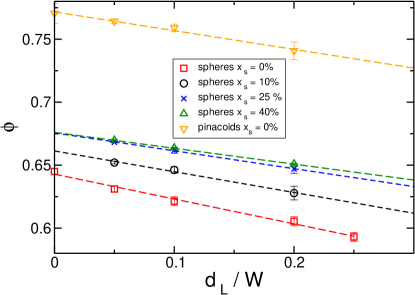
More interestingly, an excellent agreement between our data and the geometrical model is found. The corresponding values of and are reported in table 4. It should be pointed out that the value of obtained for MSP is consistent with that of the random close packing () reported in the literature Torquato2000 .
| spheres | pinacoids | ||||
|---|---|---|---|---|---|
| 0% | 10% | 25% | 40% | 0% | |
| 0.197 | 0.165 | 0.142 | 0.126 | 0.149 | |
| 0.643 | 0.661 | 0.676 | 0.676 | 0.772 | |
Note that in Ref. Desmond2009 , Desmond and Weeks compare the geometrical model with simulations of bidisperse sphere packing (50-50 binary mixture with particle size ratio of 1.4) in the absence of gravity. Our results show that the validity of this model is much broader since it still holds in the presence of gravity for monodisperse sphere packings, for bidisperse sphere packings (independently of the fraction of small grains) as well as for monodisperse pinacoid packings. This result is important in the framework of real granular materials whose grains are far from being perfect spheres.
Let us recall that the fit parameter is equal to (see section I). Our results show that when the fraction of small grains, , increases, decreases. This can be the consequence of a decrease of the distance of propagation of the sidewall effects or/and of the difference .
To address this point we will study the local variation of the solid fraction close to the sidewalls.
This is the objective of next subsection.
IV.2 Solid fraction profiles
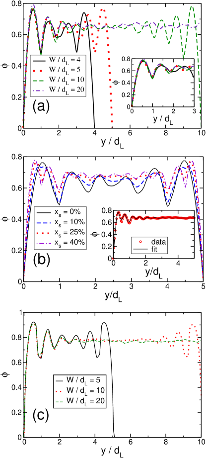
Figure 7 depicts the solid fraction profile as a function of the distance to the left sidewall for MSP (a), BSP (b) and MPP (c). The local solid fraction fluctuates with the distance from the wall, especially in the neighborhood of sidewalls and, if is large enough, it reaches a uniform value away from the sidewalls. The inset of Fig. 7(a) reports the packing fraction fluctuations as a function of the non-dimensional distance from the wall . The aforementioned fluctuations clearly reflect the layering due to the presence of sidewalls – i.e. an order propagation in the direction Suzuki2008 . For MSP, the confinement effect propagates over approximately to . As a result, packings for which to are influenced by the presence of walls over their full width. In other words, for such size, the order generated by the sidewalls propagates in the whole packing. On the contrary for BSP as well as for MPP, the propagation seems to be shorter (approximately to for BSP and about for MPP). The presence of bidispersity or non-sphericity induces disorder in the vicinity of the sidewalls which mitigates the layering. To quantify more precisely the sidewall effects we have fitted the solid fraction profiles reported in Fig. 7 by the following empirical law:
| (11) |
In this expression, the characteristic lengths of the sidewall effect propagation for large (L) and small (S) grains are respectively and . Parameter characterizes the solid fraction increase close to the sidewalls, and respectively correspond to the period and amplitude of the structuration oscillations caused to the solid fraction profile by the layering of small and large particles. For monosized packings, we use the aforementioned fit with . An example of the obtained fits is plotted in the inset of Fig. 7b. Let us stress out that the fit used is purely empirical. Our aim is to obtain a reasonable approximation for confinement effect propagation rather than a precise description of the solid fraction profiles by an equation.
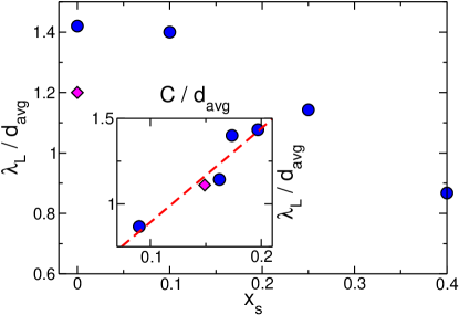
The values of (those of are not statistically relevant for ), normalized by the average grain size , obtained this way are reported in Fig. 8 for .
For sphere packings, the normalized characteristic length is found to decrease when the fraction of small spheres increases. Indeed, for we have whereas for . This decrease proves that the polidispersity mitigates the confinement effect.
Morover, the fact that
decreases with demonstrates that decreases quicker than the mean grain size.
For MPP we obtain which is smaller than the value obtained for MSP. This indicates that the sidewall effect is also mitigated by an increase in grain angularity.
Hence, characteristic length is expected to correlate with the thickness of the boundary layers introduced in equation 1. In the inset of Fig. 8 we report versus and observe a good linear correlation between these two parameters. Furthermore, the data for both sphere and pinacoid packings collapse on the same straight line whose intercept is equal to zero.
IV.3 Effect of grain/wall friction
So far, the presented simulations were performed with frictionless grains and sidewalls. However, additional simulations were performed to investigate the influence of grain/wall friction. For this purpose, the friction coefficient between grains was kept equal to zero, whereas the grain/wall friction coefficient was successively set to , and . As before, three grain packings were simulated for each grain/wall friction coefficient in order to average the measured quantities. Our aim is not to address this point, but just to mention that in our contact dynamic simulations, we found that the grain/wall friction had no effect since neither the average solid fraction nor the solid fraction profiles were affected by . This result demonstrates that the influence of confinement on packing fraction is purely geometrical.
V Packing microstructure
Section III has established that our packings are homogeneous and that they have reached a stable equilibrium with acceptable interpenetration. Then, in section IV we have verified that the simulated compaction method allows to accurately achieve the solid fraction characteristic of the random close-packed state of monodisperse sphere packings when PBC are substituted for sidewalls. Moreover this method is sufficiently repeatable to show significant influence of the confinement on the solid fraction of various grain packings. Now, section V focuses on the internal state of our packings in order to investigate the influence of confinement on their microstructure. We first investigate the presence of textural order (section V.1). Then, we study a usual characteristic to describe the microstructure of grain packings: the mean number of contacts per grains (coordination number). For various grain shapes and polydispersities, section V.2 discusses the influence of confinement on that characteristic.
V.1 Order
In this section, our aim is to investigate the presence of long-range textural order in the packings. Let us point out here that by long-range order we mean an order that extends to the system size when this size tends towards infinity (Ricci_PRE_2006, ).
In a granular packing, textural order may take various forms cambou_09 :
translational arrangements of grains that combine to form patterns, preferential orientation of the contact network, preferential orientation of non-spherical grains themselves. Each of these aspects is addressed in the following paragraphs.
First, translational arrangements are studied by means of the pair correlation function (Silbert_PRE_2002, ).
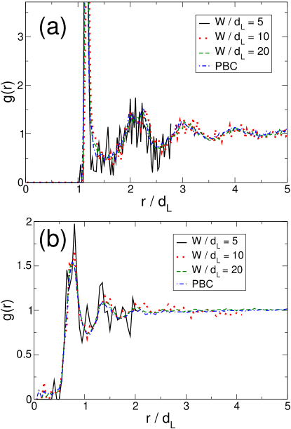
This function is depicted in Fig. 9 for MSP (a) and MPP packings (b) and for several values of . For both packings, local order extends over a few particle diameters, slightly less for MPP than for MSP due to the higher angularity of the former resulting in a loss of rotational symmetry. As a consequence, very confined packings exhibit ordering over their full size. However, for lower confinement (e.g. when or more), tends towards when increases beyond , indicating the absence of translational long range ordering within our packings.
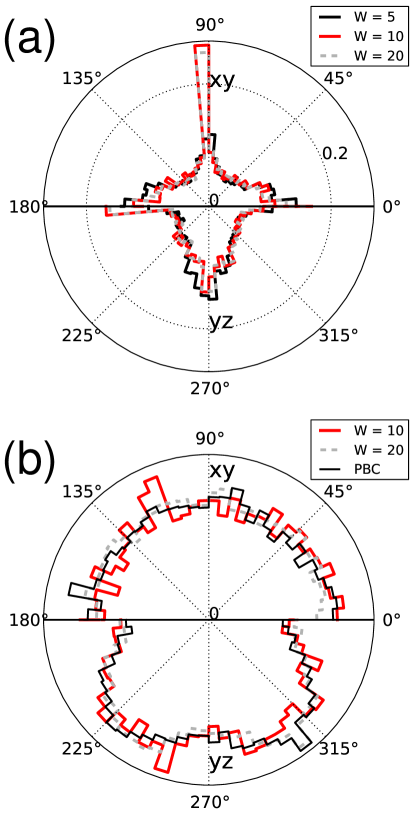
Next, the existence of preferential orientations of the contact network is investigated. For this purpose, Fig. 10 displays for various confinements representations of the distributions of contact orientations in MSP away from the bottom plane and the free surface. Given the sidewall-induced-layering evidenced in the -thick boundary layers (see section IV.2), contact from the boundary layers (Fig. 10a) have been dealt with separately from those located in the bulk region (Fig. 10b). Note that no bulk region is present in monodisperse packings where and, conversely, no boundary layer occurs in PBC packings. Furthermore, inside the boundary layers (see Fig. 10a), an anisotropy of contact orientations is visible regardless of the confinement in the , and directions, as well as at roughly to the direction in the plane and to the direction in the plane (corresponding to compact clusters of three spheres close to the sidewalls). This anisotropy is fully consistent with the vertical layering of monodisperse packings close to the sidewalls, with a larger peak in the direction due to the high proportion of sidewall-sphere contacts. Unsurprisingly, in the bulk region, Fig. 10b shows that the distribution of contact orientations remains isotropic for all these confinements. In order to assess the effect of polydispersity on the existence of preferential orientations of the contact network, 2D representations of the distributions of contact orientations are depicted in Fig. 11 for -thick packings, away from bottom plane and free surface. Observe that the substitution of by mass of small particles for large ones results in the emergence of a central -thick quasi-isotropic bulk region (see Fig. 11b). Furthermore, note that the boundary layers remain anisotropic (see Fig. 11a) although the presence of small particles in between large ones tends to disturb the vertical layering of the latter (because the centers of inertia of small particles are not necessarily coplanar with those of large particles). Hence, the anisotropy along the axes , and is mitigated, whilst other preferential orientations corresponding to various patterns made of small and large grains each in contact with the others are generated. Eventually, in order to assess the effect of grain shape on the existence of preferential orientations of the contact network, 2D representations of the distributions of contact orientations in MPP away from the bottom plane and the free surface are represented in Fig. 12 for various confinements. As for sphere packings, contacts located in boundary layers have been dealt with separately from those located in the bulk region. Inside the boundary layers, an anisotropy of contact orientations is visible regardless of the confinement in the , and directions (see Fig. 12a), and this anisotropy may be explained by the wall-induced layering just like for sphere packings. In the bulk region, Fig. 12b shows that pinacoid packings exhibit isotropic contact orientation distributions in the plane, but not along the axis where, unlike for sphere packings, some anisotropy is visible even for packings with PBC. This anisotropy may be explained by the deposition under gravity protocol, with pinacoids rotating around their center of inertia under steric hindrance contraints in order to minimize their potential energy.
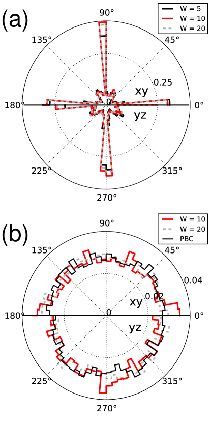
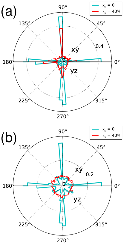
The anisotropy observed in Fig. 11b and 12b respectively for BSP with and MPP with PBC may be calculated and compared to that of the isotropic reference state depicted in Fig. 10b with PBC. Given the rotational symmetry of the contact normal orientation distributions in the plane (see Fig. 10b, 11b and 12b), the anisotropy may be quantified using a second order development of the contact orientation probability density function (see Azema_MechMat_2009 for details):
| (12) |
where:
-
•
denotes the branch vector coefficient of anisotropy derived from eigenvalues and of the fabric tensor cambou_09 ; Radjai11 ; Azema_MechMat_2009
-
•
denotes the polar coordinate in the plane
This coefficient may vary from (perfectly isotropic packing) to (perfectly anisotropic packing).
{comment}
Anisotropy of the assembly can be defined from a local variable as the orientation of the normal for the contact between particles. Orientation of a normal can be written in spherical coordinates . It is possible to define a function density of orientation of the normal for the contacts with where correspond to a small solid angle directed in the direction of and represent all the possible orientations in a three-dimensional space.
The coefficient of anisotropy of the normal for the contacts allows to measure the muddled state of the contacts between particles in granular packings. Anisotropy can be described from tensorials parameters such as fabric tensors cambou_09 ; Radjai11 . The constituents of the fabric tensor are respectively calculated in an integral and discrete way by means of the equations 13 and 14 :
| (13) |
that is
| (14) |
Besides, considering a symmetry of revolution around , the fabric tensor is diagonal. From then on, by placing this last relation in the integral equation (13) and by identifying with the constituents of the fabric tensor (14) which limits itself in his eigenvalues, we extract then the scalar parameter which condenses the information about the anisotropy of the normal for the contacts in the assembly for this given state, that is Azema_MechMat_2009 :
where et are eigen values of the fabric tensor . This coefficient can vary until a maximal value of .
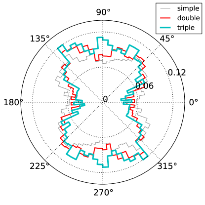
Table 5 gathers values of the branch vector coefficient of anisotropy calculated for MSP with PBC, in the bulk region of BSP with and for MPP with PBC. These values show no significant differences between the bulk region of BSP with and MSP with PBC. Furthermore, the coefficient of anisotropy of branch vectors obtained for MPP with PBC remains below , denoting a rather small anisotropy. Last, observe in Fig. 13 showing the distributions of orientations of simple (face-vertex), double (face-edge) and triple (face-face) contacts that the vertical anisotropy in MPP with PBC is identical no matter the contact type. As a consequence, no long-range contact orientation anisotropy is generated in our frictionless grain packings by the grain deposition protocol used, except a weak anisotropy generated in pinacoid packings along the axis.
Finally, the orientations of particles that are not symmetric by rotation may also be a source of anisotropy within the packing. To detect a preferential orientation of pinacoids in such a packing, one may use the nematic order parameter . Here, we recall briefly how this parameter can be determined (for details, refer to Camp_JChemPhys_1997 ; John_JChemPhys_2004 ). For each particle, if we call the unit vectors of its base of inertia (which, in our case, align with its axes of symmetry) we can define the following tensor John_JChemPhys_2004 :
and where is the number of particles and the Kronecker symbol. We apply the same definition with and . From those tensors, the nematic order parameter can be determined:
where is the eigenvector corresponding to the larger eigenvalue of the three tensors , and . is the corresponding diagonalized tensor.
{comment}
The geometry of particles can be source of anisotropy of orientation of the particles in the packings.
Nematic order parameter allows to bring to light in an assembly a direction of orientation privileged by particles. When such an orientation exists, the biaxial order parameter allows furthermore to describe the alignment of axes perpendicular particles in this direction with two fixed orthogonal directions et . In nematic phase perfectly aligned we shall have then et (Random orientation of particles in the perpendicular plan in the privileged orientation) whereas in biaxial phase perfectly aligned we shall have and Camp_JChemPhys_1997 .
These parameters are calculated in the following way. If the axes of the base of inertia of particles are also their axes of symmetry, the local base of each particle oriented with these axes allows us to build the tensor of dimension 2 following John_JChemPhys_2004 :
where is the Kronecker symbol ; we apply the same definition with and . We determine the maximal eigenvalues , et for each tensor , , and the corresponding eigenvectors. The direction of the eigenvector which corresponds with the greater eigenvalue will become the particles privileged orientation and the associated eigenvector will be noted . In the same way, the eigenvector associated to the second will be noted . Finally, the eigenvector which corresponds with the smaller eigenvalue will be noted . So nematic and biaxial order parameter are : Camp_JChemPhys_1997 :
By construction, this parameter varies between and . For each of our pinacoid packings, two values of the nematic order parameter have been calculated, one corresponding to particles located in a boundary layer, and one corresponding to particles located in the bulk region. Whatever the confinement, the nematic order parameter ranges between and in the bulk region, which is quite low and shows the absence of privileged grain orientation, whereas it is slightly higher in the boundary layers (between and ).
For non-spherical particles, the presence of faces at the grain surface can lead to global alignments between two parallel faces. Recently, Joashvili et al. Jaoshvili_PRL_2010 proposed to quantify those alignments between two particles through the following parameter:
where are respectively the faces of particles and . When the faces of the two particles are parallel we have .
In an homogeneous packing, is still negative but higher that . Its exact value, that can be close but different to , depends on the type of polyhedron Smith_PRE_2011.
To quantify the spatial propagation of that phenomenon, one can use the correlation function .
The latter quantity is reported in Fig. 14 for MPP for several values of . Function becomes constant when whatever the confinement. The value obtained in that case is consistent with the ones obtained for other types of polyhedron Smith_PRE_2010 . Therefore,
our grain packings exhibit nearly homogeneous face-face orientational
correlation, except for very short range.

As a conclusion of this subsection, frictionless grain packings used in the present work do not exhibit significant long range order, except a weak anisotropy of the contact orientation distributions observed in pinacoid packings along the axis. Furthermore, sidewalls induce order close to their location that, in the case of very confined packing, propagates over the whole system.
V.2 Coordination number
Figure 15 shows the variations of the coordination number with for MSP, BSP and MPP.
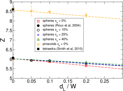
Each value is averaged over three simulations and the error bars denote the corresponding standard deviation. Preliminary examination of our results obtained with bi-periodic boundary conditions (unconfined state with ) suggests the following remarks: for sphere packings, the calculated coordination number is , which is very close to the value calculated by roux_04 in the RCP state. For pinacoid packings, the calculated coordination number is . Although no study of pinacoid packings could be found in the literature, such a high coordination number value has already been observed in disordered packings of particles having a similar shape ( calculated by Smith_PRE_2010 for packings of tetraedra upon extrapolation to the jamming point).
When confinement increases, the coordination number decreases linearly for both MSP and MPP, which is consistent with the linear decrease of the solid fraction evidenced in Fig. 6. Though, MPP coordination number values tend to be more scattered than MSP ones, which could be due to a combination of finite packing size effects with the higher level of interpenetration observed in pinacoid packings.
Nevertheless, the aforementioned linear relation between and suggests a generalization
of the geometrical model to the coordination number. For this purpose, let us define and , respectively the coordination number for the bulk region and the coordination number for the boundary layers. By writing the coordination number as the average of and weighted by the thicknesses of their respective zones (resp. and ) we obtain
| (15) |
with .
Figure 15 also shows that the influence of polydispersity on packing coordination number decreases to zero when the confinement diminishes, which is consistent with roux_05 . Indeed, in the unconfined state, the lack of contacts of small spheres with others (due to the steric hindrance of large ones) is compensated by the excess of contacts of large spheres with small ones.
| (BSP) | |
|---|---|
To investigate the coordination number decrease with increasing confinement, Fig. 16 depicts coordination number profiles in the direction (normal to the sidewalls) for sphere and for pinacoid packings.
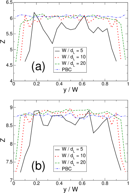
Each of these profiles is averaged over three simulations and is determined upon subdividing the packing into slices perpendicular to the direction and calculating for each slice the average number of contacts per particle having its center of inertia in the slice. In confined state, all these profiles evidence a central zone where the coordination number is almost unchanged compared to the unconfined reference state (except for sphere packings with ), and two ”drop zones” in contact with the sidewalls where the coordination number symmetrically drops by (for sphere packings) to contacts (for pinacoid packings) from their respective unconfined reference state. The thicknesses of these drop zones look identical to that of the boundary layers described
in the geometrical model Desmond2009 , leading to the same conclusion that grain angularity mitigates the effect of sidewalls on the coordination number drop in their vicinity.
To confirm this observation, we may consider the geometrical model and compare
with . For MSP, we obtain
and and for MPP and .
Note that the values of and are also comparable in the case of BSP.
The strong correlation between those two quantities shows that the propagation of the confinement effect is comparable for the two studied quantities: and .
As described in subsection II.4, pinacoid packings incorporate simple, double and triple contacts and it is of interest to investigate the effect of confinement on their respective distribution.
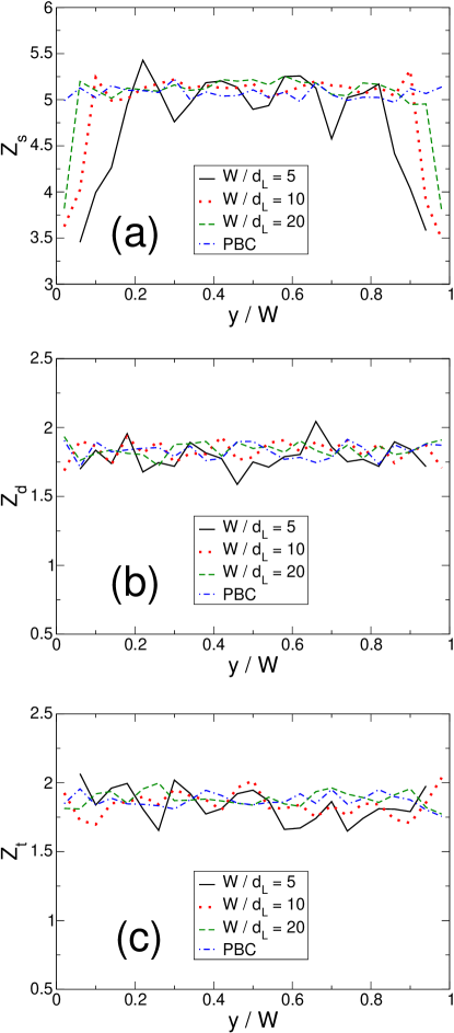
Therefore, Fig. 17 depicts the coordination number profiles of MPP for simple (a), double (b) and triple contacts (c). Like in Fig. 16, all these profiles evidence a central zone where coordination number values are almost unchanged compared to the unconfined reference state (except for sphere packings with ). These values are , and respectively for simple, double and triple contacts.
In order to check the relevance of these coordination number values, one shall observe that packings of frictionless rigid grains at equilibrium obey the following relation Roux_PRE_2000 between the degree of hypostaticity , the degree of hyperstaticity , the number of contacts that carry forces , and the number of degrees of freedom of the packing:
| (16) | |||||
If we assume that the pinacoids in our packings are randomly oriented, which seems reasonable according to the values of the nematic order parameter (see section V.1), then no motion is possible without generating work in the contacts network, which means that the degree of indeterminacy of contact forces in the packing is zero, therefore should be set to in equation V.2. Upon incorporating in equation V.2 the aforementioned coordination number values as well as that of , one obtains:
| (17) |
Observe that, for isostatic pinacoid packings (e.g. ), equation V.2 would lead to . Here, it is clear that . The level of interpenetretation calculated in subsection III.2 together with the finite size of packings may lead to a sum slightly higher that , but it is doubtful that this sum would reach upon this sole explanation. The presence of hyperstaticity in our pinacoid packings seems more realistic and at least consistent with equation 17 and with our finding of as much as 2 triple contacts per grain (). Although interesting, further investigation of the presence of hyperstaticity falls beyond the scope of the present paper.
Coming back to Fig. 17, the profiles show that MPP exhibit more simple contacts than the sum of double and triple contacts. They also evidence that confinement primarily impacts the simple contact profiles, whereas double and triple contact profiles remain unchanged. As a consequence, the vicinity of sidewalls is not a privileged location for edge-to-face or face-to-face contacts, although a drop in the simple contact profiles tends to make them look over-represented.
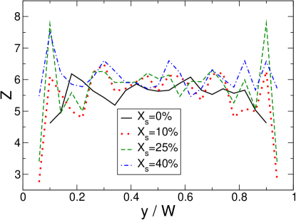
For a fixed confinement, Fig. 18 shows the influence of polydispersity on coordination number profiles in the direction (normal to the sidewalls) for sphere packings. As before, each of these profiles is averaged over three simulations and is determined upon slicing the packing perpendicular to the direction. As observed in Fig. 7b, an increasing polydispersity does not seem to impact the bulk region, but rather reduces the thickness of the boundary layers, hence mitigates the effect of sidewalls confinement on the coordination number.

Finally, like for the solid fraction, we have not observed any effect of the grain-wall friction coefficient on the coordination number of MSP.
{comment}
V.3 Orientation of the contacts
Although the solid fraction and the mean coordination numbers are often considered as the most important parameters to quantify a granular packing, they do not characterize the texture of the material. To go further, we also studied the orientation of the contacts which may be influenced by the presence of sidewalls and by the shape of particles. Figure 19 displays the distribution of the orientation of contacts for MSP and for several values of the confinement.

The effect of confinement is striking. Indeed, a clear anisotropy on the orientation of contacts is present in the , and directions. The latter anisotropies vanish as the confinement decreases, demonstrating that they are indeed a consequence of the presence of sidewalls.
Note that, in the absence of confinement, the distribution is almost isotropic. It is close to that obtained in Atman_JPCM_2005 for packings obtained by a rain-like deposition of grains.
For important confinements (), other anisotropies are also present at angles and both in the and in the planes. The effect of confinement is therefore not only visible on the direction normal to the sidewalls.

In order to test the effect of the grain shape, the distribution of the orientation of contacts is also reported for MPP in Fig. 20. The comparison of Fig. 20 with Fig. 19 clearly shows that the texture of MPP is quite different from the texture of MSP. First, the anisotropy in the direction is much less pronounced for MPP. Second, the anisotropy in the direction is always visible even in the unconfined case unlike the anisotropies in the and directions that vanish with increasing distance between sidewalls. Third, in the unconfined case, although the distribution is almost isotropic in the plane it is clearly anisotropic in the plane. In particular, the anisotropy in the direction is still clearly visible. We will go back to this point below. Broad lobes are also visible in the plane for angle and .
We also investigate the orientation of simple, double and triple contacts for MPP. The corresponding distributions are
reported in Fig. 21.
Figure 21(a) shows the distributions of simple contacts for MPP and for several gap widths.
As expected, the anisotropy in the direction vanishes as the confinement decreases.
An anisotropy is also visible in the direction but it remains much lower than the previous one.
If the granular packing is unconfined, although the anisotropies in the and directions are
no more present, the distribution is not isotropic. Broad lobes in and are indeed visible. Figure 21(b) and Fig. 21(c) show the distributions of respectively double and triple contacts for MPP and for several gap widths. In both cases, an anisotropy in the direction as well as an anisotropy in the direction are clearly visible. Unlike the former, the latter vanishes in the periodic case.
Note that in the case of double contacts the anisotropy in the direction is more pronounced than the one in the direction, except of course for periodic packings where, as mentioned above, the anisotropy in the direction vanishes.
On the contrary, in the case of triple contacts, the anisotropy in the direction is the most important whatever the gap width between sidewalls.
From previous figures, it seems that the anisotropy in the direction observed in Fig. 20 is governed by the double and triple contacts. This suggests that the gravity forces is therefore mainly supported by double and triple contacts
i.e. face-face and edge-face contacts. This behavior is consistent to the one already observed by Radjai and Azéma Azema_MechMat_2009 . These authors showed that in particular, most face-face contacts belong to strong force chains along the major principal stress direction whereas vertex-face contacts are correlated with weak forces and oriented on average along the minor principal stress direction.
VI Conclusion
In this work, we have shown how a confining boundary alters the solid fraction as well as the internal structure of static frictionless
granular materials compacted under their own weight using the non-smoothcontact dynamics simulation method. We did not restrict ourselves to sphere packings but extended our work to packings made of a particular type of polyhedra: pinacoids.
As previously reported, the presence of sidewalls induces short-range order in their vicinity. Except a weak contact orientation anisotropy observed with pinacoid packings in the vertical direction, no long-range order was observed in our packings. We have demonstrated that both the polydispersity and the angularity of grains lower the confinement effect. This effect has been observed for the solid fraction and for the coordination number.
Our results have shown that the geometrical model Verman_Nature_1946 ; Brown_Nature_1946 ; Combe_PhD_2001 ; Desmond2009 that captures the linear evolution of the solid fraction versus is valid for sphere packings as well as for pinacoid packings and that it holds whatever the packing polydispersity.
Interestingly, this model, initially derived for the packing fraction can be extended to capture the effect of confinement on the coordination number. The characteristic length quantifying the effect of the sidewalls is found to be the same for those two quantities.
Finally, we have shown that the effect of wall friction is negligible, indicating that the major influence of the confining sidewalls is geometric.
Several perspectives arise from this study, among which the need to address with more details the presence of hyperstaticity in our packings of frictionless pinacoids.
Acknowledgments
We thank F. Chevoir, J.-N. Roux, G. Saussine, N. Roquet and N. N. Medvedev for helpful conversations. Many thanks to the LMGC90 team in Montpellier for making their simulation platform freely available. We are also grateful to O. Garcin for technical support.
References
- (1) L. E. Silbert, D. Ertaş, G. S. Grest, T. C. Halsey, and D. Levine. Geometry of frictionless and frictional sphere packings. Phys. Rev. E, 65(3):031304, Feb 2002.
- (2) I. Agnolin and J.-N. Roux. Internal states of model isotropic granular packings. i. assembling process, geometry, and contact networks. Phys. Rev. E, 76:061302, Dec 2007.
- (3) N. Taberlet, P. Richard, A. Valance, W. Losert, J.-M. Pasini, J. T. Jenkins, and R. Delannay. Superstable granular heap in a thin channel. Phys. Rev. Lett., 91(26):264301, Dec 2003.
- (4) N. Taberlet, P. Richard, E. Henry, and R. Delannay. The growth of a super stable heap: An experimental and numerical study. EPL (Europhysics Letters), 68(4):515–521, 2004.
- (5) P. Jop, Y. Forterre, and O. Pouliquen. Crucial role of sidewalls in granular surface flows: consequences for the rheology. Journal of Fluid Mechanics, 541:167–192, 2005.
- (6) N. Taberlet, P. Richard, and J. E. Hinch. shape of a granular pile in a rotating drum. Phys. Rev. E, 73(5):050301, May 2006.
- (7) P. Richard, A. Valance, J.-F. Métayer, P. Sanchez, J. Crassous, M. Louge, and R. Delannay. Rheology of confined granular flows: Scale invariance, glass transition, and friction weakening. Physical Review Letters, 101(24):248002, 2008.
- (8) N. Taberlet, P. Richard, and R. Delannay. The effect of sidewall friction on dense granular flows. Computers & Mathematics with Applications, 55(2):230 – 234, 2008.
- (9) G. Pereira, M. Sinnott, P. Cleary, Kurt Liffman, Guy Metcalfe, and Ilija Sutalo. Insights from simulations into mechanisms for density segregation of granular mixtures in rotating cylinders. Granular Matter, 13:53–74, 2011.
- (10) R. Ben Aim and P. le Goff. La coordinance des empilements désordonnés de sphères. application aux mélanges binaires de sphères. Powder Technology, 2(1):1 – 12, 1968.
- (11) M. Suzuki, T. Shinmura, K. Iimura, and M. Hirota. Study of the wall effect on particle packing structure using x-ray micro computed tomography. Advanced Powder Technology, 19(2):183 – 195, 2008.
- (12) J. W. Landry, G. S. Grest, L. E. Silbert, and S. J. Plimpton. Confined granular packings: Structure, stress, and forces. Phys. Rev. E, 67(4):041303, Apr 2003.
- (13) J. W. Landry, G. S. Grest, and S. J. Plimpton. Discrete element simulations of stress distributions in silos: crossover from two to three dimensions. Powder Technology, 139(3):233 – 239, 2004.
- (14) A. Seguin, Y. Bertho, and P. Gondret. Influence of confinement on granular penetration by impact. Phys. Rev. E, 78(1):010301, Jul 2008.
- (15) L. Vanel, Ph. Claudin, J.-Ph. Bouchaud, M. E. Cates, E. Clément, and J. P. Wittmer. Stresses in silos: Comparison between theoretical models and new experiments. Phys. Rev. Lett., 84(7):1439–1442, Feb 2000.
- (16) Chu-heng Liu, H. M. Jaeger, and Sidney R. Nagel. Finite-size effects in a sandpile. Phys. Rev. A, 43(12):7091–7092, Jun 1991.
- (17) S. Courrech du Pont, P. Gondret, B. Perrin, and M. Rabaud. Wall effects on granular heap stability. EPL (Europhysics Letters), 61(4):492, 2003.
- (18) K. W. Desmond and E. R. Weeks. Random close packing of disks and spheres in confined geometries. Phys. Rev. E, 80(5):051305, Nov 2009.
- (19) L.C. Verman and S. Banerjee. Nature, 157:584, 1946.
- (20) R. L. Brown and P. G. W. Hawksley. Nature (London), 157:585, 1946.
- (21) G. Combe. Origines géométrique du comportement quasi-statique des assemblages granulaires denses : étude par simulation numérique. PhD thesis, École Nationale des Ponts et Chaussées, 2001.
- (22) A. P. F. Atman, P. Brunet, J. Geng, G. Reydellet, G. Combe, P. Claudin, R. P. Behringer, and E. Clément. Sensitivity of the stress response function to packing preparation. Journal of Physics: Condensed Matter, 17(24):S2391, 2005.
- (23) P. Ribière, P. Richard, R. Delannay, and D. Bideau. Importance of convection in the compaction mechanisms of anisotropic granular media. Phys. Rev. E, 71(1):011304, Jan 2005.
- (24) P. Ribière, P. Richard, D. Bideau, and R. Delannay. Experimental compaction of anisotropic granular media. The European Physical Journal E, 16:415–420, 2005.
- (25) K. Szarf, G. Combe, and P. Villard. Polygons vs. clumps of discs: A numerical study of the influence of grain shape on the mechanical behaviour of granular materials. Powder Technology, 208(2):279 – 288, 2011.
- (26) C. Tourenq and A. Denis. Les essais de granulats, volume 114. Rapport de recherche du Laboratoire Central des Ponts et Chaussées, Paris, 1982.
- (27) C. Murray. Phases of thin colloidal layers. MRS Bulletin, 23, 1998.
- (28) Lee-Wen Teng, Pei-Shan Tu, and Lin I. Microscopic observation of confinement-induced layering and slow dynamics of dusty-plasma liquids in narrow channels. Phys. Rev. Lett., 90:245004, Jun 2003.
- (29) R. Laniel. Caractérisations numériques d’un géomatériau renforcé par un fil. PhD thesis, Université de Montpellier 2, 2007.
- (30) J.J. Moreau. Some Numerical Methods in Multibody Dynamics : Application to Granular Materials. European J. Mech. A, 13:93–114, 1994.
- (31) J.J. Moreau and M. Jean. Numerical treatment of contact and friction : the contact dynamics method. Engineering systems design and analysis, pages 201–208, mars 1996.
- (32) M. Jean. The non-smooth contact dynamics method. Computer Methods in Applied Mechanics Engineering, 177:235–257, 1999.
- (33) F. Dubois and M. Jean. Lmgc90 une plateforme de développement dédiée à la modélisation des problèmes d’interaction. In Actes du sixième colloque national en calcul des structures - CSMA-AFM-LMS, volume 1, pages 111–118, 2003.
- (34) F. Radjaï and F. Dubois, editors. Discrete numerical simulations of granular materials. Wiley, 2011.
- (35) E. Azéma, F. Radjaï, R. Peyroux, and G. Saussine. Force transmission in a packing of pentagonal particles. Phys. Rev. E, 76:011301, Jul 2007.
- (36) G. Saussine, C. Cholet, P.E. Gautier, F. Dubois, C. Bohatier, and J-J. Moreau. Modelling ballast behaviour under dynamic loading. part1 : A 2d polygonal discrete element method approach. Comput. Methods Appl. Mech. Eng., 195:2841–2859, 2006.
- (37) F. Chevoir, M. Prochnow, J.T. Jenkins, and P. Mills. Dense granular flows down an inclined plane. In Y. Kishino, editor, Powders and grains 2001, pages 373–376, Rotterdam, 2001. Balkema.
- (38) G. Lois, A. Lemaître, and J. M. Carlson. Numerical tests of constitutive laws for dense granular flows. Phys. Rev. E, 72:051303, Nov 2005.
- (39) G. Lois, A. Lemaître, and J. M. Carlson. Emergence of multi-contact interactions in contact dynamics simulations of granular shear flows. EPL (Europhysics Letters), 76(2):318, 2006.
- (40) E. Azéma, F. Radjaï, R. Peyroux, F. Dubois, and G. Saussine. Vibrational dynamics of confined granular materials. Phys. Rev. E, 74:031302, Sep 2006.
- (41) N. Estrada, A. Taboada, and F. Radjaï. Shear strength and force transmission in granular media with rolling resistance. Phys. Rev. E, 78:021301, Aug 2008.
- (42) E. Azéma, F. Radjaï, R. Peyroux, V. Richefeu, and G. Saussine. Short-time dynamics of a packing of polyhedral grains under horizontal vibrations. The European Physical Journal E: Soft Matter and Biological Physics, 26:327–335, 2008.
- (43) E. Azéma, F. Radjai, and G. Saussine. Quasistatic rheology, force transmission and fabric properties of a packing of irregular polyhedral particles. Mechanics of Materials, 41(6):729 – 741, 2009.
- (44) E. Azéma and F. Radjaï. Stress-strain behavior and geometrical properties of packings of elongated particles. Phys. Rev. E, 81:051304, May 2010.
- (45) J.C. Macrae and W.A. Gray. Significance of The Properties of Materials in the Packing of Real Spherical Particles. British Journal of Applied Physics, 12(4):164–172, 1961.
- (46) S. Emam, J.-N. Roux, J. Canou, A. Corfdir, and J.C. Dupla. Granular Packings Assembled by Rain Deposition : an Experimental and Numerical Study. Powder and Grains 2005, 2005.
- (47) Z. P. Zhang, L. F. Liu, Y. D. Yuan, and A. B. Yu. A simulation study of the effects of dynamic variables on the packing of spheres. Powder Technology, 116(1):23 – 32, 2001.
- (48) J.-N. Roux. Internal State of Granular Assemblies Near Random Close Packing. arXiv:cond-mat/0405358v1, 2004.
- (49) J.-N. Roux. Geometric origin of mechanical properties of granular materials. Phys. Rev. E, 61:6802–6836, Jun 2000.
- (50) B. Smit and D. Frenkel. Understanding Molecular Simulation. From Algorithms to Applications. Academic Press, San Diego, 2001.
- (51) G. Saussine. Contribution à la modélisation de granulats tridimensionnels : application au ballast. PhD thesis, Université de Montpellier 2, 2004.
- (52) P. Richard, A. A. Gervois, L. Oger, and J.-P. Troadec. Order and disorder in hard-sphere packings. EPL (Europhysics Letters), 48(4):415–420, 1999.
- (53) P. Richard, L. Oger, J.P. Troadec, and A. Gervois. A model of binary assemblies of spheres. The European Physical Journal E, 6:295–303, 2001.
- (54) S. Torquato, T. M. Truskett, and P. G. Debenedetti. Is random close packing of spheres well defined? Phys. Rev. Lett., 84:2064–2067, Mar 2000.
- (55) A. Ricci, P. Nielaba, S. Sengupta, and K. Binder. Lack of long-range order in confined two-dimensional model colloidal crystals. Phys. Rev. E, 74:010404, Jul 2006.
- (56) B. Cambou, M. Jean, and F. Radjai, editors. Micromechanics of Granular Materials. ISTE, London, UK, 2009.
- (57) P. J. Camp and M. P. Allen. Phase diagram of the hard biaxial ellipsoid fluid. The Journal of Chemical Physics, 106(16):6681–6688, 1997.
- (58) B. S. John, A. Stroock, and F. A. Escobedo. Cubatic liquid-crystalline behavior in a system of hard cuboids. The Journal of Chemical Physics, 120(19):9383–9389, 2004.
- (59) K. C. Smith, M. Alam, and T. S. Fisher. Athermal jamming of soft frictionless platonic solids. Phys. Rev. E, 82:051304, Nov 2010.
- (60) J.-N. Roux, F. Chevoir, and F. Toussaint. Etats de Compacité Maximale pour les Assemblages de Grains Sphériques : Étude par Simulation Numérique. Bulletin des Laboratoires des Ponts et Chaussées, 2005. also avaible in english online.