Realizing an -target-qubit controlled phase gate in cavity QED: An approach without classical pulses
Abstract
We propose a way to realize a multiqubit controlled phase gate with one qubit simultaneously controlling target qubits using atoms in cavity QED. In this proposal, there is no need of using classical pulses during the entire gate operation. The gate operation time scales as only and thus the gate can be performed faster when compared with sending atoms through the cavity one at a time. In addition, only three steps of operations are required for realizing this -target-qubit controlled phase gate. This proposal is quite general, which can be applied to other physical systems such as various superconducting qubits coupled to a resonator, NV centers coupled to a microsphere cavity or quantum dots in cavity QED.
pacs:
03.67.Lx, 42.50.Dv, 42.50.PqI. INTRODUCTION
Quantum computing has attracted much attention since quantum computers can in principle solve computational problems much more efficiently than classical computers or process some computational tasks that are intractable with their classical counterparts [1-3]. In the past decade, various physical systems have been considered for building up quantum-information processors. Among them, the cavity QED with neutral atoms is a very promising approach for quantum information processing, because a cavity can act as a quantum bus to couple atoms and information can be stored in certain atomic energy levels with long coherence time.
It is known that a quantum computation network can be constructed using one-qubit and two-qubit logic gates [4,5]. Based on cavity QED technique, many theoretical methods have been proposed for implementing a two-qubit controlled-phase or controlled-NOT gate with atoms [6-12]. Moreover, a two-qubit quantum controlled phase gate between a cavity mode and an atom has been experimentally demonstrated [13].
Research on quantum computing has recently moved toward the physical realization of multiqubit controlled quantum gates, which are useful in quantum information processing. In principle, any multiqubit gate can be decomposed into two-qubit gates and one-qubit gates. However, when using the conventional gate-decomposition protocols to build up a multiqubit controlled gate [5], the procedure usually becomes complicated as the number of qubits increases and the single-qubit and two-qubit gates required for the gate implementation heavily depends on the number of qubits (especially, for a large ). Therefore, it is important to find a more efficient way to realize multiqubit controlled gates.
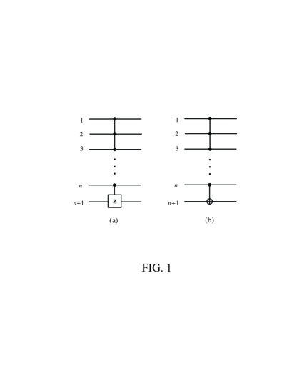
During the past few years, many schemes have been proposed for implementing multiqubit controlled gates in different physical systems, e.g., atoms in cavity QED [14,15], trapped ions [16], atomic ensembles [17], superconducting qubits coupled to a cavity or resonator [18,19], and nitrogen-vacancy (NV) centers [20]. The proposals [14-20] are mainly for implementing a multiqubit controlled-phase or controlled-NOT gate with multiple-control qubits acting on one target qubit (Fig. 1). This type of multiqubit controlled gates is of significance in quantum information processing such as quantum algorithms (e.g., [2,21]) and quantum error-correction protocols [22].
In this work, we focus on another type of multiqubit controlled gates, i.e, a multiqubit phase or CNOT gate with one qubit simultaneously controlling target qubits (Fig. 2). This type of controlled gates with target qubits is useful in quantum information processing. For instances, they have applications in error correction [23], quantum algorithms (e.g., the Discrete Cosine Transform [24]), and quantum cloning [25]. In addition, they can be used to prepare Greenberger-Horne-Zeilinger (GHZ) states [26]. It should be mentioned here that the gate in Fig. 1 can be used to prepare states which are locally-equivalent to W-class states [27], but can not be applied to create GHZ states. As is well known, the GHZ states and the W-class states can not be interchanged to each other, and both of them play an important role in quantum information processing and communication.
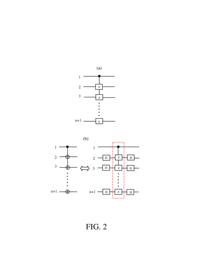
For simplicity, we denote this multiqubit phase gate with one qubit simultaneously controlling target qubits [see Fig. 2(a)] as an -target-qubit controlled phase gate. It can be seen from Fig. 2(a) that the -target-qubit controlled phase gate consists of two-qubit controlled-phase (CP) gates. Each two-qubit CP gate involved in this multiqubit gate has a shared control qubit (labelled by ) but a different target qubit (labelled by or ). For two qubits, there are a total of four computational basis states and The two-qubit CP gate acting on qubit and qubit () is defined as and which implies that if and only if the control qubit is in the state , a phase flip happens to the state of the target qubit , but nothing happens otherwise. According to the definition of a two-qubit CP gate here, it is easy to see that this -target-qubit controlled phase gate with one qubit simultaneously controlling target qubits () is described by the following unitary operator
| (1) |
where the subscript represents the control qubit , while represents the target qubit ; and is the identity operator for the qubit pair (), which is given by , with From Eq. (1), it can be seen that the operator induces a phase flip (from the sign to the sign) to the logical state of each target qubit when the control qubit is initially in the state , and nothing happens otherwise.
In this paper, we will present a way for implementing the -target-qubit controlled phase gate with () atoms in cavity QED. Here, the () atoms are one control atom acting as a control qubit and target atoms each playing a role of a target qubit. This proposal has the following features: (i) there is no need of using classical pulses during the entire operation; (ii) The gate operation time scales as only and thus the gate can be performed faster when compared with sending atoms through the cavity one by one; (iii) the two-qubit CP gates involved can be simultaneously performed; and (v) the gate implementation requires only three steps of operations. This proposal is quite general, which can be applied to other physical systems such as various superconducting qubits coupled to a resonator, nitrogen-vacancy (NV) centers coupled to a microsphere cavity or quantum dots in cavity QED.
Note that an -target-qubit CNOT gate, shown in Fig. 2(b), can also be achieved using the present proposal. This is because the n-target-qubit CNOT gate is equivalent to the -target-qubit controlled phase gate discussed above, plus two Hadamard gates on each target qubit [Fig. 2(b)].
This paper is organized as follows. In Sec. II, we briefly review the basic theory of atom-cavity resonant interaction and atom-cavity off-resonant interaction. In Sec. III, we show how to realize an -target-qubit controlled phase gate using atoms in cavity QED. In Sec. IV, we study fidelity of the gate operation. A brief discussion and the summary are given in Sec. V.
II. BASIC THEORY
The gate implementation requires two types of atom-cavity interaction, which are described as follows.
A. Atom-cavity resonant interaction. Consider a two-level atom, say, atom , with a ground level and an excited level Assume that the cavity mode is resonant with the transition of the atom. The interaction Hamiltonian in the interaction picture can be written as
| (2) |
where and are the photon creation and annihilation operators of the cavity mode, is the resonant coupling constant between the cavity mode and the transition of the atom, and . It is easy to find that the time evolution of the states and of the atom and the cavity mode, governed by the Hamiltonian (2), is described by
| (3) |
while the state remains unchanged. Here and below, the and are the vacuum state and the single-photon state of the cavity mode, respectively.
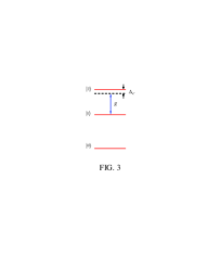
B. Atom-cavity off-resonant interaction. Consider atoms () each having three levels and (Fig. 3). Suppose that the cavity mode is coupled to the transition of each atom but highly detuned (decoupled) from the transition between any other two levels (Fig. 3). In the interaction picture, the interaction Hamiltonian of the whole system is given by
| (4) |
where is the detuning between the cavity mode frequency and the transition frequency of the atoms, is the coupling constant between the cavity mode and the transition, and
For the case of (i.e., the cavity mode is off-resonant with the transition of each atom), there is no energy exchange between the atoms and the cavity mode. However, the coupling between the atoms and the cavity mode may induce a phase to the atomic states. This kind of coupling, which can induce a phase but does not cause energy exchange, is often called “dispersive coupling” in quantum optics, or it is said that the cavity mode is dispersively coupled to the atoms. In this case, based on the Hamiltonian (4), one can obtain the following effective Hamiltonian [6,28,29]
| (5) | |||||
where the two terms in the first line represent the photon-number-dependent Stark shifts, while the two terms in the second line describe the “dipole” coupling between the two atoms () mediated by the cavity mode. When the level of each atom is not occupied, the Hamiltonian (5) reduces
| (6) |
The time-evolution operator for the Hamiltonian (6) is
| (7) |
Here, is the time-evolution operator acting on the cavity mode and the atom (), which is given by
| (8) |
One can easily find that the operator results in the following state transformation
| (9) |
where This result (9) demonstrates that a phase shift is induced to the state of the atom in the case when the cavity mode is in the single-photon state For we have i.e., which implies that a phase flip is induced to the state of the atom by the cavity photon. In addition, the first two lines of Eq. (9) show that the states and of atom remain unchanged when the cavity mode is in the vacuum state and the third line of Eq. (9) shows that the state of atom remains unchanged when the cavity mode is in the single-photon state
The operator is a product of the operators and which can be seen from Eq. (7). Based on Eq. (7), Eq. (8) and the result (9), one can easily find:
(i) The states and of each of atoms () remain unchanged when the cavity mode is in the vacuum state
(ii) The state of each of atoms () remains unchanged when the cavity mode is in the single-photon state
(iii) For a phase flip happens to the state of each of atoms () simultaneously, in the case when the cavity mode is in the single-photon state To see this, consider the state for three atoms () and the cavity mode. One can easily verify that by applying the operator to the state the state becomes for which shows that a phase flip is induced to the state of each of three atoms () at the same time, by the cavity photon.
The results (i-iii) given here will be applied to the gate implementation discussed in next section.
III. IMPLEMENTATION OF AN N-TARGET-QUBIT CONTROLLED PHASE GATE
To realize the gate, we will employ a two-level atom and identical three-level atoms (). The three levels of each of atoms () are shown in Fig. 3. For each atom, the two lowest levels and represent the two logical states of a qubit. In the following, atom acts as a control while each one of the atoms () plays a target role.
We suppose that during the following gate operation, (i) the cavity mode is resonant with the transition of atom and (ii) the cavity mode is off-resonance with the transition of atoms () but highly detuned (decoupled) from the transition between any other two levels of atoms (). These conditions can in principle be met by prior adjustment of the cavity mode frequency or by appropriately choosing atoms to have the desired level structure. Note that the cavity mode frequency for both optical cavities and microwave cavities can be changed in various experiments (e.g., see [30-33]).
The cavity mode is initially in the vacuum state The procedure for implementing the -target-qubit controlled phase gate described by Eq. (1) is listed below:
Step (i): Send atom through the cavity for an interaction time by choosing the atomic velocity appropriately. After atom exits the cavity, the state for atom and the cavity mode remains unchanged, while their state changes to as described by Eq. (3).
Step (ii): Send atoms () through the cavity for an interaction time by choosing the atomic velocity appropriately. After atoms () leave the cavity, (i) the states and of each atom remain unchanged in the case when the cavity mode is in the vacuum state (ii) the state of each atom remains unchanged when the cavity mode is in the single-photon state but (iii) the state of each atom changes to (i.e., a phase flip happens to the state of each of atoms and ) when the cavity mode is in the single-photon state, as discussed in the previous subsection B.
Step (iii): Send atom back through the cavity for an interaction time . After atom leaves the cavity, the state of atom and the cavity mode remains unchanged, while their state changes to
Note that the level of each of atoms () is not affected by the cavity mode during the operation of step (ii). This is because the cavity mode was assumed to be highly detuned (decoupled) from the transition and the transition of each of the atoms (), as mentioned before.
One can check that the -target-qubit controlled phase gate, described by Eq. (1), was obtained with () atoms (i.e., the control atom 1 and the target atoms and ) after the above manipulation.
Let us consider a three-qubit example in order to see better how the multi-target-qubit controlled phase gate described by Eq. (1) is realized after the operations above. For three qubits, there are a total of eight computational basis states from to . Based on the results given above for each step of operations, it can be easily found that for three-qubit computational basis states and , the time evolution of the states of the whole system after each step of operations is given by
| (18) | |||
| (23) | |||
| (28) |
Here and above, is an abbreviation of the state of atoms () with The result (10) shows that when the control atom is initially in the state , a phase flip happens to the state of atoms () while the cavity mode returns to its original vacuum state, after the above three-step operation.
On the other hand, it is obvious that the following states of the system
| (29) |
remain unchanged during the entire operation. This is because no photon was emitted to the cavity during the operation of step (i) due to energy conservation, when atom is initially in the state . Hence, it can be concluded from Eq. (10) that a two-target-qubit controlled phase gate, i.e., a phase gate with one qubit simultaneously controlling two target qubits, was achieved with three atoms (i.e., the control atom and the target atoms and ) after the above process.
One can see that our gate implementation above requires sending atoms through a cavity. We should point out that the technique by sending atoms through a cavity to have the atoms dispersively coupled with the cavity mode was previously proposed and has been widely used by the quantum information community [28,34,35].
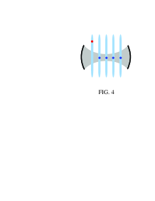
As shown above, atoms were sent through the cavity. Alternatively, as illustrated in Fig. 4, each atom can be trapped inside an optical lattice [14,36,37] and then can be moved into, out of, or back into a cavity, by moving the lattice [14,36,37].
From the above descriptions, it can be seen that the total operation time is given by
| (30) |
Because of (set above), we can define with Thus, Eq. (12) can be rewritten as showing that the operation time is independent of the number of qubits. In contrast, when employing the protocol, which is based on sending the target atoms through the cavity one at a time, the large detuning is (i.e., with and the total operation time is which increases linearly with the number of the target atoms. Therefore, by using the present proposal, the gate can be performed faster especially for a large number
IV. FIDELITY
Let us now study the fidelity of the gate operations. We note that since the resonant interaction between the atom and the cavity is used in steps (i) and (iii), these two steps can be completed within a very short time (e.g., by increasing the resonant atom-cavity coupling constant ), such that the dissipation of the atom and the cavity is negligibly small. In this case, the dissipation of the system would appear in the operation of step (ii) due to the use of the atom-cavity dispersive interaction. During the operation of step (ii), the dynamics of the lossy system, composed of the cavity mode and the atoms (), is determined by
| (31) |
where is the Hamiltonian (4), (with , and ), is the decay rate of the cavity mode, is the decay rate of the level of the atoms () via the decay path (here, ). The fidelity of the gate operations is given by
| (32) |
where is the state of the whole system after the above three-step gate operations, in the ideal case without considering the dissipation of the system during the entire gate operation; and is the final density operator of the whole system after the gate operations are performed in a real situation.
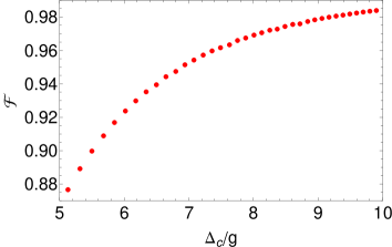
We now numerically calculate the fidelity of the gate operations. As an example, we consider realizing a four-target-qubit controlled phase gate, using a two-level control atom and four identical three-level target atoms (). The four identical target atoms () are chosen as Rydberg atoms with the principle quantum numbers 49, 50, and 51, which correspond to the three levels and as depicted in Fig. 3, repectively. For the Rydberg atoms chosen here, the energy relaxation time of the level and the energy relaxation time of the level are both s (e.g., see [30,38,39]). Without loss of generality, we assume that each of the five atoms is initially in the state and the cavity mode is in the vacuum state before the gate. The expression for the ideal state of the system after the entire gate operation is straightforward (not shown here to simply our presentation). As a conservative estimation, we consider and . In addition, we choose KHz [38] and s. Our numerical calculation shows that a high fidelity can be achieved when the ratio is about 10 (Fig. 5).
For Rydberg atoms chosen here, the transition frequency is GHz [30]. The cavity mode frequency is then GHz for . For this value of the cavity mode frequency and the s chosen in our calculation, the required quality factor of the cavity is Note that cavities with a high have been reported [40]. Our analysis given here shows that implementing a phase gate with one qubit simultaneously controlling four target qubits (i.e., a four-target-qubit controlled phase gate) with atoms is possible within the present cavity QED technique.
We should mention that the motivation for using the circular Rydberg states is that they have long energy relaxation times and have been widely used in quantum information processing [6,30,38,39,41-43].
V. DISCUSSION AND CONCLUSION
Before conclusion, we should point out that in 2010, Yang, Liu and Nori proposed a first scheme for implementing a phase gate of one qubit simultaneously controlling target qubits based on cavity QED [44]. In the same year, Yang, Zheng and Nori proposed another scheme for realizing a multiqubit tunable phase gate of one qubit simultaneously controlling target qubits within cavity QED [45]. As discussed in [44,45], these two schemes require applying a pulse to each of qubit systems inside a cavity. The purpose of this work is to present an alternative approach for implementing the proposed gate. As shown above, application of a pulse is not required and thus our present scheme differs from the previous ones in [44,45]. Because of no pulses needed, the present scheme is much improved when compared with the previous proposals in [44,45].
We have proposed a way to realize a multiqubit controlled phase gate with one qubit simultaneously controlling target qubits using atoms in cavity QED. As shown above, the gate can be implemented: (i) by using one cavity through three-step operations only, (ii) without need of using classical pulses during the gate operations, (iii) faster when compared with sending atoms through a cavity or loading atoms into a cavity one by one; and (iv) in an operation time which scales as only. We believe that this work is of interest because it provides a way for implementing the proposed multiqubit gate useful in quantum information processing. Finally, we note that this proposal is quite general, which can be applied to other physical systems such as various superconducting qubits coupled to a resonator, NV centers coupled to a microsphere cavity or quantum dots in cavity QED.
ACKNOWLEDGMENTS
C.P. Yang was supported in part by the National Natural Science Foundation of China under Grant No. 11074062, the Zhejiang Natural Science Foundation under Grant No. Y6100098, the funds from Hangzhou Normal University, and the Open Fund from the SKLPS of ECNU. Q.P. Su was supported by the National Natural Science Foundation of China under Grant No. 11147186.
References
- (1) D. Deutsch, Proceedings of the Royal Society A 400, 97 (1985).
- (2) P.W. Shor, In Proceedings of the 35th Annual Symposium on Foundations of Computer Science (IEEE Computer Society Press, Santa Fe, NM, 1994).
- (3) L.K. Grover, Phys. Rev. Lett. 79, 325 (1997).
- (4) D.P. DiVincenzo, Phys. Rev. A 51, 1015 (1995); Science 270, 255 (1995).
- (5) A. Barenco, C.H. Bennett, R. Cleve, D.P. DiVincenzo, N. Margolus, P. Shor, T. Sleator, J.A. Smolin, H. Weinfurter, Phys. Rev. A 52, 3457 (1995).
- (6) S.B. Zheng, G.C. Guo, Phys. Rev. Lett. 85, 2392 (2000).
- (7) D. Jaksch, J.I. Cirac, P. Zoller, Phys. Rev. Lett. 85, 2208 (2000).
- (8) E. Solano, M.F. Santos, P. Milman, Phys. Rev. A 64, 024304 (2001).
- (9) A. Biswas, G.S. Agarwal, Phys. Rev. A 69, 062306 (2004).
- (10) S.B. Zheng, Phys. Rev. Lett. 95, 080502 (2005); Phys. Rev. A 70, 052320 (2004); Phys. Rev. A 71, 062335 (2005).
- (11) C.P. Yang, S.I. Chu, S. Han, Phys. Rev. A 70, 044303 (2004).
- (12) X.B. Zou, Y.F. Xiao, S.B. Li, Y. Yang, G.C. Guo, Phys. Rev. A 75, 064301 (2007); G.W. Lin, X.B. Zou, M.Y. Ye, X.M. Lin, G.C. Guo, Phys. Rev. A 77, 032308 (2008).
- (13) A. Rauschenbeutel, G. Nogues, S. Osnaghi, P. Bertet, M. Brune, J.M. Raimond, S. Haroche, Phys. Rev. Lett. 83, 5166 (1999).
- (14) L.M. Duan, B. Wang, H.J. Kimble, Phys. Rev. A 72, 032333 (2005).
- (15) Y.F. Xiao, X.B. Zou, G.C. Guo, Phys. Rev. A 75, 014302 (2007); G.W. Lin, X.B. Zou, X.M. Lin, G.C. Guo, Phys. Rev. A 79, 064303 (2009).
- (16) X. Wang, A. Srensen, K. Mlmeret, Phys. Rev. Lett. 86, 3907 (2001).
- (17) H.Z. Wu, Z.B. Yang, S.B. Zheng, Phys. Rev. A 82, 034307 (2010).
- (18) C.P. Yang, S. Han, Phys. Rev. A 72, 032311 (2005).
- (19) C.P. Yang, S. Han, Phys. Rev. A 73, 032317 (2006).
- (20) W.L. Yang, Z. Yin, Z. Xu, M. Feng, J. Du, arXiv: 1006.0278.
- (21) L.K. Grover, Phys. Rev. Lett. 80, 4329 (1998).
- (22) P.W. Shor, Phys. Rev. A 52, R2493 (1995); L.K. Grover, Phys. Rev. Lett. 80, 4329 (1998); A.M. Steane, Phys. Rev. Lett. 77, 793 (1996).
- (23) F. Gaitan, Quantum Error Correction and Fault Tolerant Quantum Computing (CRC Press, USA, 2008).
- (24) T. Beth, M. Rötteler, Quantum Information (Springer, Berlin, 2001) Vol 173 Ch 4 p96.
- (25) S.L. Braunstein, V. Buzek, M. Hillery, Phys. Rev. A 63, 052313 (2001).
- (26) M. Šašura, V. Buzek, Phys. Rev. A 64, 012305 (2001).
- (27) W. Dür, G. Vidal, J.I. Cirac, Phys. Rev. A 62, 062314 (2000).
- (28) S.B. Zheng, Phys. Rev. Lett. 87, 230404 (2001).
- (29) A. Srensen, K. Mlmer, Phys. Rev. Lett. 82, 1971 (1999).
- (30) M. Brune, E. Hagley, J. Dreyer, X. Maitre, A. Maali, C. Wunderlich, J. M. Raimond, S. Haroche, Phys. Rev. Lett. 77, 4887 (1996).
- (31) M. Sandberg, C.M. Wilson, F. Persson, T. Bauch, G. Johansson, V. Shumeiko, T. Duty, P. Delsing, Appl. Phys. Lett. 92, 203501 (2008).
- (32) A. P. Laloy, F. Nguyen, F. Mallet, P. Bertet, D. Vion, D. Esteve, J. Low Temp. Phys. 151, 1034 (2008).
- (33) J.R. Johansson, G. Johansson, C.M. Wilson, F. Nori, Phys. Rev. Lett. 103, 147003 (2009).
- (34) C.C. Gerry, Phys. Rev. A 53, 2857 (1996).
- (35) S.B. Zheng, G.C. Guo, Phys. Rev. Lett. 85, 2392 (2000).
- (36) A. Beige, D. Braun, B. Tregenn, P.L. Knight, Phys. Rev. Lett. 85, 1762 (2000).
- (37) J.A. Sauer, K.M. Fortier, M.S. Chang, C.D. Hamley, M.S. Chapman, Phys. Rev. A 69, 051804(R) (2004).
- (38) S. Osnaghi, P. Bertet, A. Auffeves, P. Maioli, M. Brune, J.M. Raimond, S. Haroche, Phys. Rev. Lett. 87, 037902 (2001).
- (39) J. M. Raimond, M. Brune, and S. Haroche, Rev. Mod. Phys. 73, 565 (2001).
- (40) S. Kuhr et al., Appl. Phys. Lett. 90, 164101 (2007).
- (41) X.B. Zou, W. Mathis, Phys. Rev. A 72, 013809 (2005).
- (42) C. Sayrin et al., Nature (London) 477, 73 (2011).
- (43) X. Zhou, I. Dotsenko, B. Peaudecerf, T. Rybarczyk, C. Sayrin, S. Gleyzes, J.M. Raimond, M. Brune, and S. Haroche, Phys. Rev. Lett. 108, 243602 (2012).
- (44) C.P. Yang, Y.X. Liu, and F. Nori, Phys. Rev. A 81, 062323 (2010).
- (45) C.P. Yang, S.B. Zheng, and F. Nori, Phys. Rev. A 82, 062326 (2010).