Nonlocal response in plasmonic waveguiding with extreme light confinement
Abstract
We present a novel wave equation for linearized plasmonic response, obtained by combining the coupled real-space differential equations for the electric field and current density. Nonlocal dynamics are fully accounted for, and the formulation is very well suited for numerical implementation, allowing us to study waveguides with subnanometer cross-sections exhibiting extreme light confinement. We show that groove and wedge waveguides have a fundamental lower limit in their mode confinement, only captured by the nonlocal theory. The limitation translates into an upper limit for the corresponding Purcell factors, and thus has important implications for quantum plasmonics.
pacs:
78.67.Uh, 78.67.Lt, 71.45.Lr, 73.20.Mf, 41.20.JbWave propagation along dielectric waveguide structures has over the years been extended also to plasmonic systems with waveguide modes in the form of surface-plasmon polaritons. Plasmonic waveguides have attracted considerable attention during the past decade, primarily due to their ability to support extremely confined modes, i.e., modes that do not exhibit a diffraction-limited cutoff for progressively smaller waveguide cross sections but transform themselves into their electrostatic counterparts Gramotnev and Bozhevolnyi (2010). Investigations of nanowire Ditlbacher et al. (2005), groove Bozhevolnyi et al. (2005) and wedge Moreno et al. (2008) waveguides, shown to ensure extreme light confinement, raise a natural interest in the influence of nonlocal effects on strongly confined plasmonic modes García de Abajo (2008). Waveguiding by metal nanowires Aers et al. (1980) and more recently plasmonic focusing by conical tips Ruppin (2005); Wiener et al. (2012) have been studied in the context of nonlocal response. However, with the exception of few analytical studies of simple planar geometries Boardman et al. (1976); Yan et al. (2012), nonlocal effects in the dispersion properties of complex waveguides remain unexplored, a circumstance that can partly be explained by the added complexity due to nonlocal effects as compared to the widespread framework of the local-response approximation (LRA) Maier (2007).
There is also another good reason to look for nonlocal effects in extreme light confinement. Subwavelength mode confinement implies large effective Purcell factors and thereby strong coupling of single emitters to nearby plasmonic waveguide modes Chang et al. (2006). The latter opens a doorway to quantum optics with surface plasmons, including the possibilities for realization of single-photon transistors Chang et al. (2007) and long-distance entanglement of qubits González-Tudela et al. (2011). Since one would expect that the plasmonic mode confinement is fundamentally limited by nonlocal effects, similarly to nonlocal limits in the field enhancement of localized plasmon excitations Toscano et al. (2012a); Ciracì et al. (2012), studies of the plasmonic mode confinement beyond the LRA are of great interest for quantum plasmonics. More specifically, in the LRA higher single-photon efficiencies Chang et al. (2006) and Purcell factors Chang et al. (2007) have been found to occur for smaller waveguide radii , and the limit is commonly taken to estimate the strongest light-matter interactions. Nonlocal response effects become increasingly important in this limit, which is an important motivation for our present study of nonlocal effects for highly confined plasmonic waveguides.
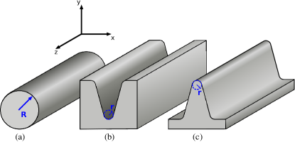
In this Letter, we derive a novel wave equation which fully takes into account the nonlocal dynamics of an often-employed hydrodynamical model (HDM). We apply the wave equation to plasmonic waveguides (Fig. 1) with extreme light confinement, defined by the subnanometer dimensions of the waveguide cross section. After stringent bench-marking of our approach against the analytically tractable case of nanowires with circular cross-section, we analyze in detail groove and wedge waveguides and demonstrate the existence of fundamental limits in their mode confinement and Purcell factors, imposed by the nonlocal effects. At the same time, our results reveal that there is room for downsizing present-day quantum plasmonic devices before these fundamental limitations set in.
The nonlocal response, or spatial dispersion, is a consequence of the quantum many-body properties of the electron gas, which we here take into account within a semi-classical model Bloch (1933); Barton (1979); Boardman (1982); Pitarke et al. (2007). In this model the equation-of-motion for an electron in an electrical field is supplemented with a hydrodynamic pressure term originating from the quantum kinetics of the electron gas. By linearization, the plasmonic response is governed by the following pair of coupled real-space differential equations Raza et al. (2011):
| (1a) | |||
| (1b) |
Here, the term is a correction to Ohm’s law and scales as within the Thomas–Fermi model Halevi (1995) with being the Fermi velocity. For simplicity we neglect here any interband effects present in real metals; these can be included straightforwardly Toscano et al. (2012b); sup . In our numerical solutions we will consider Drude parameters appropriate for silver Rodrigo et al. (2008). Assuming a hard-wall confinement associated with a high work function, the boundary conditions for the current at the metal surface become particularly simple: the tangential component is unrestricted while the normal component vanishes due to the current continuity and vanishing of all electron wave functions at the surface Raza et al. (2011); Yan et al. (2012).
For analytical progress one can eliminate the current from Eq. (1a), thereby arriving at an integral equation where a dyadic Green’s function accounts for the nonlocal dynamics of the electron gas Mortensen et al. (2012); Mortensen (2013). Alternatively, the coupled equations (1a) and (1b) form a natural starting point for a numerical treatment of arbitrarily shaped metallic nanostructures, e.g., with a state-of-the-art finite-element method Toscano et al. (2012b); Hiremath et al. (2012). Recently, we employed this approach to study field enhancement and SERS in groove structures Toscano et al. (2012a). However, for waveguiding geometries we seek solutions of the form leading to an eigenvalue problem for with a six-component eigenvector . In that context the coupled-equation formulation is numerically less attractive. Here, instead, we eliminate the current from Eq. (1b), a procedure that, after straightforward manipulations using standard vector calculus sup , results in an appealingly compact, but yet entirely general nonlocal wave equation:
| (2a) | |||
| (2b) |
Here, the operator contains the nonlocal effects. In the limit , reduces to the usual Drude dielectric function used in the LRA. Thus, with a simple rewriting we have turned the coupled-wave equations into a form reminiscent of the usual wave equation, with all aspects of nonlocal response contained in the Laplacian term in . This is the main theoretical result of this Letter. In passing, we note that with Eq. (2b) we immediately recover the dispersion relation for bulk plasmons in translationally invariant plasma sup . Clearly, the single-line form is beneficial for the conceptual understanding and further analytical progress, as well as for numerical implementations: the additional Laplacian does not add any complications beyond those already posted by the double-curl operator on the left-hand side equation. Likewise the boundary condition that was imposed on the current in Eq. (1) translates into an additional boundary condition on the electric field in Eq. (2), see sup . While Eq. (1) can be solved numerically for scattering problems Toscano et al. (2012b); Hiremath et al. (2012); Toscano et al. (2012a) and some waveguide problems Huang et al. (2013), the result in Eq. (2) is clearly a major advancement for efficient and accurate numerical eigenvalue solutions in waveguiding geometries with arbitrarily shaped waveguide cross sections. In particular, differential operations reduce to a Laplacian and the dimension of the eigenvalue problem is reduced from six field components to only three.
We now apply the developed formalism to the waveguide configurations of Fig. 1 which can provide extreme light confinement Gramotnev and Bozhevolnyi (2010): i) metal nanowires with circular cross sections Ditlbacher et al. (2005) where analytical solutions Ruppin (2005) are available for benchmarking of the numerics, ii) grooves in metal Bozhevolnyi et al. (2005), and iii) metal wedges Moreno et al. (2008). In addition to the usual mode characteristics, effective index and propagation length, we also evaluate the effective mode area: , where is the effective mode volume associated with the Purcell effect, i.e.,
| (3) |
where is the electromagnetic energy functional sup . The cross-sectional integral extends over the volumes and occupied by metal and air, respectively, while the evaluation of the maximal energy density is restricted to the air region where dipole emitters can be placed.
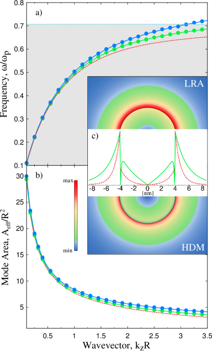
The dispersion curves and effective mode areas (normalized to the nanowire cross section) calculated for silver nanowires of different radii [Fig. 2(a,b)] exhibit a blueshift and increased mode area (for fixed ) when taking nonlocal effects into account. The numerical results of Eq. (2) show excellent agreement with the corresponding analytical results previously derived from Eq. (1) Ruppin (2005). Importantly, nonlocal dynamics influences strongly the mode field distribution [see Fig. 2(c)], because, contrary to the LRA case, the normal component of the electrical field within the HDM is continuous across the interfaces (this is a special case for a Drude metal without interband effects and surrounded by vacuum sup ). It is indeed seen [Fig. 2(c)] that is discontinuous on the boundary in the local case, while it varies continuously across the boundary in the nonlocal case. This variation occurs in a region extending over nm, that is of the order of the Fermi wavelength of silver.
The results for cylindrical nanowires, while demonstrating the main effects of nonlocal dynamics on the mode characteristics, indicate that the quantitative changes are modest even for very small radii (Fig. 2). In order to explore fundamental limitations, one has to consider the limit of vanishing radii of curvature. While subnanometer radii appear unrealistic for nanowires, fabrication of grooves cut in metal and metal wedges, e.g., by nanoimprint lithography Nielsen et al. (2008), can in fact result in nm-sharp edges with corresponding nm-sized wedge modes Moreno et al. (2008). We expect that nonlocal effects then come into play.
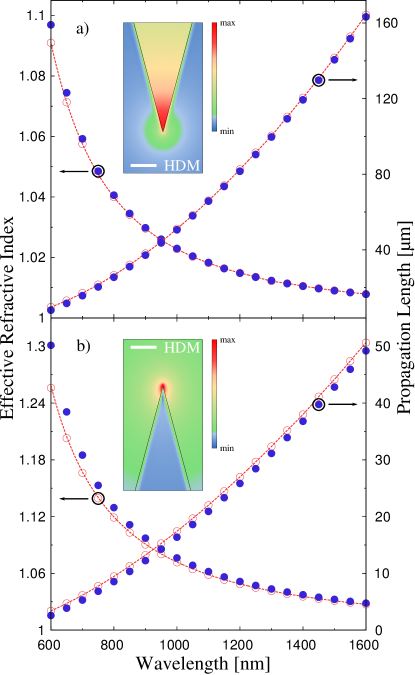
Rather surprisingly, the mode effective index and propagation length calculated for silver grooves and wedges (Fig. 3) exhibit even weaker influence of the nonlocal effects as compared to the case of nanowires (Fig. 2). In fact, there is no noticeable difference between the LRA- and HDM-based results obtained for 1-nm-radius of edges. In the limit of mathematically sharp edges, the mode effective index becomes only slightly larger and the propagation length slightly smaller than those calculated for 1 nm edge radius (Fig. 3). We explain this result by the fact that groove and wedge plasmonic modes are only partially affected by the very tip, being distributed also and predominantly over flat edges (see insets in Fig. 3).
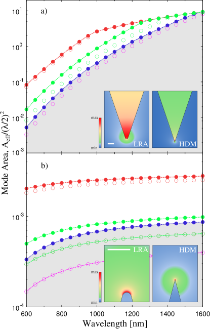
The situation changes drastically when one considers the mode confinement, using the mode area associated with the Purcell factor, Eq. (3). We recall that the field enhancement calculated within the LRA grows without bound for progressively sharper pointed structures while it remains finite when calculated within HDM Toscano et al. (2012a); Ciracì et al. (2012). Analogously, in the present case, one may expect that the mode area calculated within the LRA decreases without bound for a decreasing edge radius, while it may saturate within the HDM. LRA-based simulations for subnanometer radii of edges show (Fig. 4) that the mode area indeed tends to zero, without any apparent saturation. This trend is more pronounced for wedges than for grooves, because the wedge geometry ensures generally a better mode confinement [cf. Figs. 4(a) and (b)], as was also noted previously Moreno et al. (2008). At the same time, the simulations conducted within the HDM demonstrate clearly the existence of a lower bound for the mode area which remains finite even for mathematically sharp edges (blue circles in Fig. 4). The associated Purcell factors can be estimated by inverse of the normalized mode areas displayed in Fig. 4 Oulton et al. (2008). Thus, our calculations show that there is a fundamental limit for the maximum Purcell factors achievable with plasmonic waveguides. It is interesting that the upper limit of Purcell factors evaluated in this way decreases noticeably in the long-wavelength regime. This feature is related to a general weakening of all plasmonic effects, including waveguiding Gramotnev and Bozhevolnyi (2010), for longer wavelengths (with metals approaching the limiting case of perfect conductors). At the same time, in the case of wedges, these factors remain substantial even at telecom wavelengths, with the propagation lengths becoming considerably long (Fig. 3) and amenable for circuitry application. It should also be borne in mind that the plasmonic field confinement in both grooves and wedges increases for smaller opening angles Bozhevolnyi et al. (2005); Moreno et al. (2008), so that even larger Purcell factors can be achieved, albeit at the expense of shorter propagation.
In conclusion, using a novel wave equation accounting for nonlocal dynamics, we considered plasmonic waveguides with extreme light confinement and demonstrated the existence of a fundamental limit in their mode confinement imposed by nonlocal effects. Our results imply fundamental limitations in the corresponding Purcell factors, showing at the same time the possibility of achieving very high Purcell factors with V-groove and wedge waveguides that ensure sufficiently long propagation lengths for applications in quantum plasmonics. Here, we have focused on single-connected metal geometries where dominating currents are naturally of an Ohmic nature, whereas tunneling currents may cause important limitations too in e.g. closely spaced metallic objects Esteban et al. (2012). Finally, beyond the linear response fundamental limitations may arise due to nonlinearities Ginzburg et al. (2010).
Acknowledgments. This work was financially supported by an H. C. Ørsted Fellowship (W.Y.) and the Center for Nanostructured Graphene (CNG) is sponsored by the Danish National Research Foundation, Project DNRF58.
References
- Gramotnev and Bozhevolnyi (2010) D. K. Gramotnev and S. I. Bozhevolnyi, Nat. Photonics 4, 83 (2010).
- Ditlbacher et al. (2005) H. Ditlbacher, A. Hohenau, D. Wagner, U. Kreibig, M. Rogers, F. Hofer, F. R. Aussenegg, and J. R. Krenn, Phys. Rev. Lett. 95, 257403 (2005).
- Bozhevolnyi et al. (2005) S. I. Bozhevolnyi, V. S. Volkov, E. Devaux, and T. W. Ebbesen, Phys. Rev. Lett. 95, 046802 (2005).
- Moreno et al. (2008) E. Moreno, S. G. Rodrigo, S. I. Bozhevolnyi, L. Martín-Moreno, and F. J. García-Vidal, Phys. Rev. Lett. 100, 023901 (2008).
- García de Abajo (2008) F. J. García de Abajo, J. Phys. Chem. C 112, 17983 (2008).
- Aers et al. (1980) G. C. Aers, A. D. Boardman, and B. V. Paranjape, J. Phys. F: Metal Phys. 10, 53 (1980).
- Ruppin (2005) R. Ruppin, Phys. Lett. A 340, 299 (2005).
- Wiener et al. (2012) A. Wiener, A. I. Fernández-Domínguez, A. P. Horsfield, J. B. Pendry, and S. A. Maier, Nano Lett. 12, 3308 (2012).
- Boardman et al. (1976) A. D. Boardman, B. V. Paranjape, and Y. O. Nakamura, Phys. Stat. Sol. (b) 75, 347 (1976).
- Yan et al. (2012) W. Yan, M. Wubs, and N. A. Mortensen, Phys. Rev. B 86, 205429 (2012).
- Maier (2007) S. A. Maier, Plasmonics: Fundamentals and Applications (Springer, New York, 2007).
- Chang et al. (2006) D. E. Chang, A. S. Sørensen, P. R. Hemmer, and M. D. Lukin, Phys. Rev. Lett. 97, 053002 (2006).
- Chang et al. (2007) D. E. Chang, A. S. Sørensen, E. A. Demler, and M. D. Lukin, Nat. Phys. 3, 807 (2007).
- González-Tudela et al. (2011) A. González-Tudela, D. Martín-Cano, E. Moreno, L. Martín-Moreno, C. Tejedor, and F. J. García-Vidal, Phys. Rev. Lett. 106, 020501 (2011).
- Toscano et al. (2012a) G. Toscano, S. Raza, S. Xiao, M. Wubs, A.-P. Jauho, S. I. Bozhevolnyi, and N. A. Mortensen, Opt. Lett. 37, 2538 (2012a).
- Ciracì et al. (2012) C. Ciracì, R. T. Hill, J. J. Mock, Y. Urzhumov, A. I. Fernández-Domínguez, S. A. Maier, J. B. Pendry, A. Chilkoti, and D. R. Smith, Science 337, 1072 (2012).
- Bloch (1933) F. Bloch, Z. Phys. A 81, 363 (1933).
- Barton (1979) G. Barton, Rep. Prog. Phys. 42, 963 (1979).
- Boardman (1982) A. Boardman, Electromagnetic Surface Modes. Hydrodynamic theory of plasmon-polaritons on plane surfaces. (John Wiley and Sons, Chichester, 1982).
- Pitarke et al. (2007) J. Pitarke, V. Silkin, E. Chulkov, and P. Echenique, Rep. Prog. Phys. 70, 1 (2007).
- Raza et al. (2011) S. Raza, G. Toscano, A.-P. Jauho, M. Wubs, and N. A. Mortensen, Phys. Rev. B 84, 121412(R) (2011).
- Halevi (1995) P. Halevi, Phys. Rev. B 51, 7497 (1995).
- Toscano et al. (2012b) G. Toscano, S. Raza, A.-P. Jauho, N. A. Mortensen, and M. Wubs, Opt. Express 20, 4176 (2012b).
- (24) See Supplemental Material.
- Rodrigo et al. (2008) S. G. Rodrigo, F. J. García-Vidal, and L. Martín-Moreno, Phys. Rev. B 77, 075401 (2008).
- Mortensen et al. (2012) N. A. Mortensen, G. Toscano, S. Raza, N. Stenger, W. Yan, A.-P. Jauho, S. Xiao, and M. Wubs, AIP Conf. Proc. 1475, 28 (2012).
- Mortensen (2013) N. A. Mortensen (2013), arXiv:1306.4651.
- Hiremath et al. (2012) K. R. Hiremath, L. Zschiedrich, and F. Schmidt, J. Comp. Phys. 231, 5890 (2012).
- Huang et al. (2013) Q. Huang, F. Bao, and S. He, Opt. Express 21, 1430 (2013).
- Nielsen et al. (2008) R. B. Nielsen, I. Fernandez-Cuesta, A. Boltasseva, V. S. Volkov, S. I. Bozhevolnyi, A. Klukowska, and A. Kristensen, Opt. Lett. 33, 2800 (2008).
- Oulton et al. (2008) R. F. Oulton, G. Bartal, D. F. P. Pile, and X. Zhang, New J. Phys. 10, 105018 (2008).
- Esteban et al. (2012) R. Esteban, A. G. Borisov, P. Nordlander, and J. Aizpurua, Nat. Commun. 3, 825 (2012).
- Ginzburg et al. (2010) P. Ginzburg, A. Hayat, N. Berkovitch, and M. Orenstein, Opt. Lett. 35, 1551 (2010).