Data Mapping for Unreliable Memories
Abstract
Future digital signal processing (DSP) systems must provide robustness on algorithm and application level to the presence of reliability issues that come along with corresponding implementations in modern semiconductor process technologies. In this paper, we address this issue by investigating the impact of unreliable memories on general DSP systems. In particular, we propose a novel framework to characterize the effects of unreliable memories, which enables us to devise novel methods to mitigate the associated performance loss. We propose to deploy specifically designed data representations, which have the capability of substantially improving the system reliability compared to that realized by conventional data representations used in digital integrated circuits, such as 2’s-complement or sign-magnitude number formats. To demonstrate the efficacy of the proposed framework, we analyze the impact of unreliable memories on coded communication systems, and we show that the deployment of optimized data representations substantially improves the error-rate performance of such systems.
I Introduction
The continuous shrinkage of semiconductor devices during recent years has led to the enormous success of digital signal processing (DSP) systems by enabling the realization of ever more sophisticated and powerful implementations, which have become ubiquitous in our daily lives. Such an evolution was—up to now—relying on the assumption that the underlying hardware is able to perform computations and store data in a 100% reliable manner. However, it is now becoming apparent that such a trend may come to an end due to the increasing effect of semiconductor-process variability as well as reliability issues that threaten the correct circuit functionality, especially for CMOS technology nodes beyond 45 nm. Specifically, the small size of semiconductor devices in combination with delicate fabrication processes lead to a wide variability of transistor characteristics inside and among fabricated dies that may lead to failures. In order to maintain an acceptable fabrication yield under these conditions, the inclusion of design guard-bands and the design for the worst case has become a necessity [1, 2, 3]. Unfortunately, these precautions are costly in terms of the associated silicon area- and power overhead and, thus, render the design of cost-effective and power-efficient DSP systems significantly challenging. In addition, the application of effective low-power techniques, such as aggressive voltage-frequency scaling, makes the fabricated systems even more sensitive to process variations, which further diminishes their use in practice [4, 5].
Memories are particularly susceptible to process variations as their operation is highly dependent on the characteristics between neighboring transistors on the fabricated die. In order to ensure 100% reliable operation, costly error-correction coding schemes or novel bit-cell topologies are required to tackle the high failure probability of traditional bit-cells, which can lead to more than 30% area overhead [6, 7]. In addition, these techniques come with a significant overhead in terms of energy efficiency, which is rather unacceptable considering the fact that the share of memories in modern digital systems is continuously increasing [8]. In many cases, such error-correction mechanisms evidently waste resources since they serve merely as precaution against worst-case conditions, which only occur in a fraction of the fabricated circuits and memory cells. For some applications, such as wireless communication or multimedia, memories are already dominating both silicon area and power consumption.
Consequently, realizing cost-effective and energy-efficient DSP systems in the near future requires a paradigm shift from the assumption of 100% reliable operation to fault-tolerant DSP systems that are robust against implementation on unreliable silicon [9]. Interestingly, various applications and algorithms (e.g., for wireless communication systems or video processing) are inherently fault tolerant as they are naturally able to deal with stochastic data already corrupted by noise and interference. It has been observed that this inherent fault-tolerance can be exploited to allow for a certain amount of errors induced by unreliable silicon components without degrading the system performance noticeably, provided that the corresponding algorithms and system architectures are designed to take such hardware errors into account [10, 11, 12, 13].
I-A Contributions
By arguing that memories in modern DSP systems are particularly prone to unreliable operation, we investigate the impact of defects in memories on the performance of DSP systems. Specifically, we propose to reduce this impact by choosing data representations that are different from the ones typically employed in digital integrated circuits. Our contributions are summarized as follows:
-
•
We present a novel framework to analyze the impact of data representations on their performance in unreliable DSP systems.
-
•
We introduce the “stuck-at-channel” as a realistic model for bit-cells in unreliable memories.
-
•
We show that the choice of the data representation has a significant impact on the system performance in presence of unreliable memories.
-
•
We formulate the problem of finding favorable data representations as an optimization problem based on the memory input-data distribution and an application-specific cost function.
As a proof of concept, we apply the proposed framework to a coded communication system and show that optimized data representations significantly increase the robustness against defects in memories compared to that of data representations commonly used in digital integrated circuits.
I-B Paper Outline
The remainder of this paper is organized as follows. In Sec. II, we introduce the framework and discuss the impact of the choice of different (non-redundant) binary-valued data representations in the context of unreliable memories. We also show how different data representations can be optimized for improving robustness against unreliable memories. In Sec. III, we consider a coded communication system as a specific application example, and we provide simulation results to quantify the impact of optimized data representations on two relevant coding schemes. We conclude in Sec. IV.
II Optimized Data Representations for Unreliable Memories
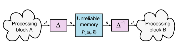
We consider an unreliable memory as depicted in Fig. 1a), which is surrounded by two processing blocks in a general DSP system. The discrete input data with is assumed to be distributed according to the probability mass function . In order to store data in the unreliable memory, each symbol is mapped to a vector with binary-valued entries and dimension bit. We refer to as the (binary-valued) label of . In what follows, we make frequent use of the bijective mapping function and its inverse , which implement and ; the mapping function defines the (binary-valued) data-representation.
Commonly used data representations in digital systems are the 2’s complement (2C) or the sign-magnitude (SM) number formats. Both data representations allow for the efficient implementation of basic arithmetic operations in digital integrated circuits [14]. As it will be shown next, the choice of the data representation has a significant impact on the robustness of systems containing unreliable memories. Furthermore, we will show that 2C or SM are not necessarily good choices in many practical application scenarios.
II-A Probabilistic Models for Unreliable Memories
In the remainder of the paper, we focus on unreliable memories in which the stored labels are subject to probabilistic errors. In particular, we model the process of storing the input data values (physically represented by its label) as an i.i.d. non-binary probabilistic channel that maps input labels to output labels according to a label cross-over probability mass function (see Fig. 1a). This label cross-over probability depends on the employed model for physical memory bit-cell errors, which are not necessarily uncorrelated within the bits belonging to the same symbol.111In reality, errors could also be correlated among the bits of different symbols. For the sake of simplicity of exposition, however, our focus is on this simplified model.
II-A1 Binary-symmetric channel (BSC)
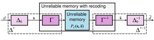
A straightforward model for errors in the individual bit-cells of unreliable memories is the BSC [10, 11]. In this case, the non-binary channel is described by parallel and independent BSCs for each bit-cell with bit-flip probability . The associated label cross-over probabilities thus correspond to [10]
where denotes the Hamming distance between the two labels and .
II-A2 Stuck-at channel
Unfortunately, the BSC fault model is not particularly relevant when considering embedded memories with very-large scale integration (VLSI) in nanometer silicon processes that are affected by process variations [15]. To arrive at a more realistic model of the true physical effects, we propose a new channel model that is more representative for the typically applied fault model for VLSI memories. We refer to this new channel model as the stuck-at channel (SAC). The fault model on which the SAC is based upon assumes that each bit-cell fails independently with a bit-cell error probability . However, in contrast to the BSC model, the stuck-at-channel model further assumes that a faulty bit cell is either stuck-at-0 or stuck-at-1 with equal probability. Physically, this effect refers to a node in the circuit being either shortened to power or ground, or to the inability of a circuit or transistor to pull a node sufficiently strong to either side of the rails. Consequently, the label cross-over probabilities for the SAC fault model correspond to
| (1) |
II-A3 Comparison between BSC and SAC
In Fig. 2, we compare the BSC and SAC fault models by plotting their label cross-over probability and depending on the Hamming distance for , and and . We can observe that the BSC fault model is rather pessimistic compared to the SAC fault model, especially for large Hamming distances. In the remainder of this paper, we use exclusively study the SAC fault model, since it reflects the behavior of practical implementations more accurately. We emphasize, however, that the general discussion and observations remains valid for other fault models.
II-B Optimized Data Representations
In order to minimize the amount of errors introduced by unreliable memories, without adding redundancy to the data representation (e.g., by means of coding), we propose to use specifically optimized data representations. The choice of such non-redundant representations is driven by the desire to minimize the associated hardware overhead and to sustain as much system performance as possible, even if data is not stored 100% reliably.
II-B1 Optimal data representations
We start by characterizing the impact of the unreliable memory on the system with an application-specific cost function that depends on the data-mapping function . We then choose an optimized data representation defined by the mapping , which minimizes the cost function for the specified memory input-data distribution and for the label cross-over probability according to
| (2) |
We emphasize that the number of choices for representing data symbols is . While for bit an exhaustive evaluation of the 40’320 possible candidate mappings is still feasible, requires already the consideration of candidates. Hence, for one must resort to sophisticated algorithms to identify good data representations. In the following, we limit our studies to ; the development of optimization algorithms suitable for is part of on-going work.
II-B2 Example cost function
Consider the mean squared error (MSE) between the memory input and the corrupted output as an example for a cost function . With this, we can measure the amount of errors induced by the SAC fault model depending on the mapping function as follows:
| (3) |
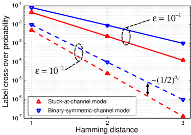
To illustrate the impact of the mapping function on the MSE we consider an input symbol alphabet of 8 integers and two different distributions222To maintain symmetry, we set . as shown in Fig. 3. In this example, the bit-cell error probability of the unreliable memory is set to . In order to properly account for differences in the signal power for the two considered distributions, we show the signal-to-mean-squared-error ratio (SER) defined as for all possible mappings in Fig. 3. We observe that the choice of the data mapping function has, indeed, a significant impact on the quality of the signal at the output of the unreliable memory. Specifically, the different data representations cover an SER range of roughly 4.5 dB with the commonly used 2C and SM representations clearly outperformed by the corresponding optimal mapping functions .
II-C Data Recoding
As observed in the example above, the choice of the data representation has a significant impact on the MSE incurred by unreliable memories and, hence, must be optimized in order to achieve maximum robustness. However, the use of optimized custom data representations is very impractical for digital systems as they usually rely on specific data representations that enable the efficient implementation of arithmetic operations in hardware. Hence, we propose data recoding as an approach to render the issue of custom data representations for memories transparent to the surrounding system. With this approach, we let the system employ a fixed (and hardware-friendly) data mapping but add a recoding function to the memory input as depicted in Fig. 1b). The recoding function relabels the memory input-labels such that . At the memory output, the inverse recoding function is applied to recover the data representation employed by the surrounding system. Note that the recoding function can be implemented by simple look-up tables. Therefore, data recoding can be considered to be a low-complexity technique to increase the robustness of DSP systems containing unreliable memories, while leaving the surrounding processing blocks untouched.
III Application to Communication Systems
As an application example of the proposed framework, we now study the impact of data representations on the performance of a coded digital communication receiver containing unreliable memories. First, we investigate the general impact of data representations on the achievable communication rates and then, we analyze the associated error-rate performance for repetition coding and convolutional codes.
III-A System Model
III-A1 Transmitter and AWGN channel
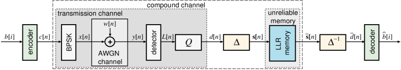
We consider the communication system introduced in [10] and depicted in Fig. 4. A sequence of information bits , , is encoded into a sequence of coded bits , , using a rate forward error-correction code. The coded bits are then mapped to binary phase shift keying (BPSK) symbols that are transmitted over an AWGN channel, modeled as , where denotes the received signal and . At the receiver, a soft-output detector computes log-likelihood ratio (LLR) values for each coded bit based on the received signal and the noise variance according to [16].
III-A2 Receiver with LLR quantizer
In the receiver, the LLR values are passed through a uniform -bit scalar quantizer . We assume a scalar quantization scheme with fractional bits and integer bits such that . The effect of the quantizer is defined as [17]
| (4) |
where denotes rounding towards . Note that (4) enforces a symmetric output distribution of the quantized LLRs with . Also note that due to , the label becomes a redundant label that is not used by the system. In order to cope with the possibility that this label appears at the output of an unreliable memory, we define . We note that the quantization scheme in (4) allows for a scaling of the input LLRs by the parameter , which allows one to adjust the quantization range to the application at hand (see, e.g., [17, 18]).
III-A3 Unreliable memory
In the communication system shown in Fig. 4, the quantized LLR values are then mapped to binary-valued labels using the data mapping function and stored in an unreliable LLR memory with label cross-over probabilities following the stuck-at-channel model. In practice, an unreliable memory could be used for data (de-)interleaving or as a large buffer that stores the LLR values of several data (re-)transmissions in modern wireless communication systems employing hybrid-ARQ (automatic repeat-request), such as 3GPP-HSPA [19].
III-B Impact of Data Representations on Mutual Information
III-B1 Compound channel
As depicted in Fig. 4, the combination of the transmission channel and the unreliable memory forms a (memory-less) compound channel with binary-valued channel inputs and binary-valued output label vector [10]. The transmission channel is characterized by the conditional probabilities of observing the channel output given the transmitted coded bit is , i.e.,
| (5) |
The compound channel, on the other hand, is characterized by the conditional probabilities of observing the label at the output of the unreliable LLR memory given that the coded bit was transmitted. Using (5) and the label cross-over probability of the unreliable LLR memory modeled by , these probabilities correspond to
| (6) |
which enables us to calculate the mutual information of the compound channel as follows [20]:
| (7) |
III-B2 Simulation results and discussion
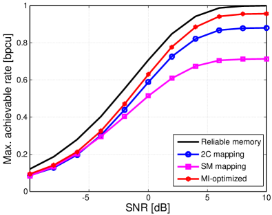
We now study the impact of data representations on the achievable rate of the considered system, assuming a fixed LLR quantizer with bit. To this end, we numerically determine with the aid of Monte-Carlo simulations for different AWGN-channel signal-to-noise ratios (SNR) and a memory bit-cell error probability of . The mutual information (III-B1) is evaluated for different data mapping functions. Fig. 5 shows the achievable rates for different data representations. As a reference, we show the achievable rate for a reliable LLR memory (with ). Furthermore, we choose as the cost function and perform an exhaustive search over all possible mappings for each SNR point (note that a different mapping may be required for each SNR). The performance of the mappings delivering the highest achievable rates for each SNR level are shown in Fig. 5 (with label ‘MI-optimized’).
We can observe that, in contrast to the MI-optimized data mapping, the two common number representations in digital circuits, namely 2C and SM, significantly limit the achievable rate, while 2C clearly outperforms SM. The fact that SM is outperformed by 2C for high SNRs can be explained as follows: In the high-SNR regime, the LLR distribution becomes bimodal with the most-positive and most-negative quantization bin (i.e., and ) having the highest probability. In this case, a bit-flip of the sign bit for the SM representation causes a large error, i.e., it maps to and vice-versa with high probability. Furthermore, both number representations incur a significant rate loss at low SNR values compared to the data mappings that maximize the mutual information. For example, at a rate of 0.5 bit per channel use (bpcu) this loss is roughly 0.5 dB and 1 dB for 2C and SM, respectively.
III-C Optimized Data Mapping for Repetition Coding
We next show that the chosen data representation has a significant impact on the bit error-rate (BER) performance. To this end, we assume that the communication system shown in Fig. 4 employs a rate-1/2 repetition code. Repetition coding is the basic model for hybrid-ARQ, which is a key feature in many modern wireless communications systems, such as 3GPP-HSPA [19], which specifies a rapid retransmission of erroneously received data blocks. For systems employing hybrid-ARQ, the LLR memory in Fig. 4 serves as a buffer that stores the LLRs of the individual (re-)transmissions. In practical systems, this buffer can be very large (i.e., storing the LLRs of multiple transmitted code blocks) and, hence, corresponding silicon realizations would benefit from high-density memories that are prone to unreliable operation.
III-C1 System model
In the example investigated here, we consider only two uncoded transmissions (i.e., ) and assume that the quantized LLRs of the first transmission are buffered in the unreliable LLR memory and then combined with the quantized LLR values from the second transmission. The combined LLR values are then sliced to 0 or 1 by the decoder in Fig. 4 depending on their sign.
III-C2 Cost function for repetition coding
In order to minimize the impact of the unreliable LLR memory on the system’s error-rate performance, we are interested in a cost function for repetition coding that enables us to identify a suitable data mapping function. Since the BER determines the performance of the system, we set . For repetition coding, this cost function can be established analytically as the sum of the probability that the combined LLR is smaller than zero having sent and the probability that the is greater or equal than 0 having sent , i.e.,
| (8) |
III-C3 Simulation results and discussion
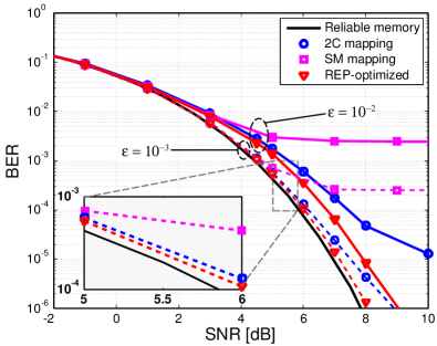
In Fig. 6 we compare the BER performance of the repetition-coding system for different data representations assuming two different bit-cell error probabilities, i.e., (solid curves) and (dashed curves). We set , which allows us to optimize in (8) exhaustively over all possible data mappings for each SNR operating point. This approach yields the optimal data mapping in terms of the system’s BER performance (labeled ‘REP-optimized’ in Fig. 6).
We see from Fig. 6 that the data representation not only affects the achievable rates (cf. Fig. 5) but also the BER-performance of the system employing a particular error-correction scheme. In this particular repetition-coding example for , the commonly deployed data representations exhibit a high error-floor and suffer from severe SNR penalties; again, 2C outperforms SM. The optimized mapping, however, yields significantly better BER performance. For higher bit-cell reliability, e.g., , the BER-performance loss of 2C and SM to the ones optimized for is still pronounced. While SM exhibits an unacceptably high error floor, the 2C data representation loses roughly 0.5 dB and 1 dB at a BER of 10-5 and 10-6, respectively, compared to the mappings optimized for repetition coding.
III-D Optimized Data Mapping for Convolutional Coding
As a second example, we assume that the encoder in Fig. 4 corresponds to the rate-1/2, 256-state convolutional code as specified in 3GPP-HSPA [19]. On the receiver side, we deploy a soft-input Viterbi decoder to generate estimates for the transmitted bits [21]. We note that convolutional codes remain to be the most common channel codes found in today’s (wireless) communication systems and, thus, the robustness of the Viterbi decoder against memory defects is of significant practical interest. In this example, the unreliable LLR memory corresponds to the (typically large) memory used for LLR de-interleaving. We are again interested in the effect of data representations on the BER performance for systems employing unreliable memories.
III-D1 Cost function for Viterbi decoding
The derivation of an analytical expression for the error-rate performance of the soft-input Viterbi decoder is difficult, in general. It is, however, important to realize that the Viterbi algorithm [21] computes its decisions on the basis of distances between branch metrics, which are used to find the maximum-likelihood solution. These branch metrics correspond to summations of LLR values, and, hence, are directly affected by the unreliable LLR memory. Consequently, the unreliable LLR memory induces branch-metric cross-over probabilities from branch metrics computed at the input of the unreliable LLR memory to the branch metrics at its output
which are a function of the memory cross-over probability and the LLR distribution . Furthermore, the branch metrics computed at the input of the unreliable memory follow the distribution , a consequence of . To arrive at a cost function that preserves distances between the branch metrics, we propose to minimize the mean squared branch-metric error (MSBE)
| (9) |
i.e., we set the cost function to .
III-D2 Simulation results and discussion
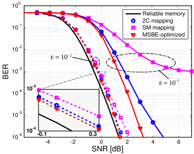
In Fig. 7, we show the BER-performance of the system for different data representations and two memory bit-cell error probabilities, i.e., (solid curves) and (dashed curves). We set and optimize the data mapping separately for each SNR point by exhaustive evaluation of . The BER-performance of these optimized data mappings is shown in Fig. 7 (labeled by ‘MSBE-optimized’).
We observe that the chosen data representation has a significant impact on the performance of the soft-input Viterbi algorithm. Hence, careful selection of the data mapping function is of paramount importance in systems containing unreliable memories. We furthermore observe that the cost function proposed in (III-D1) is able to significantly increase the robustness against unreliable memories for communication systems relying on convolutional codes compared to the use of conventional number representations, such as 2C and SM.
IV Conclusions
In this paper, we have studied the impact of unreliable memories on digital signal processing (DSP) systems. In particular, we have introduced the stuck-at-channel as a realistic model for bit-cells in unreliable memories, such as high-density memories implemented in advanced semiconductor technologies. We have observed that the data representation must be chosen carefully according to a cost function suitable for the given application to minimize the impact of unreliable memories on the system performance. To highlight the efficacy of the proposed framework, we have considered two practical application examples in a coded wireless communication system. For repetition coding and convolutional codes, our results demonstrate that the deployment of optimized data representations enables substantial gains in terms of the error-rate performance. In particular, we find that the two most common data representations used in digital integrated systems, namely 2’s complement and sign-magnitude, are generally outperformed by data mappings optimized for the application at hand. Hence, the proposed data recoding method can be considered to be an effective low-complexity method to improve the robustness of general DSP systems that contain unreliable memories.
References
- [1] J. Rabaey, Low Power Design Essentials. Springer, 2009.
- [2] S. Bhunia and S. Mukhopadhyay, Low-Power Variation-Tolerant Design in Nanometer Silicon. Springer, 2010.
- [3] S. Borkar, T. Karnik, and V. De, “Design and reliability challenges in nanometer technologies,” in Proc. 41st ACM/IEEE Design Automation Conf., Jul. 2004, p. 75.
- [4] Z. Chishti, A. Alameldeen, C. Wilkerson, W. Wu, and S.-L. Lu, “Improving cache lifetime reliability at ultra-low voltages,” in Proc. 42nd Annual IEEE/ACM Internat. Symp. Microarchitecture, Dec. 2009, pp. 89–99.
- [5] C. Wilkerson, H. Gao, A. R. Alameldeen, Z. Chishti, M. Khellah, and S.-L. Lu, “Trading off cache capacity for reliability to enable low voltage operation,” in Proc. 35th Annual IEEE Internat. Symp. Computer Architecture, 2008, pp. 203–214.
- [6] S.-T. Zhou, S. Katariya, H. Ghasemi, S. Draper, and N. S. Kim, “Minimizing total area of low-voltage SRAM arrays through joint optimization of cell size, redundancy, and ECC,” in Proc. IEEE Internat. Conf. Computer Design, Oct. 2010, pp. 112–117.
- [7] Y. Emre and C. Chakrabarti, “Memory error compensation techniques for JPEG2000,” in Proc. IEEE Workshop Signal Process. Syst., Oct. 2010, pp. 36–41.
- [8] “Everything You wanted to Know About SOC Memory (White Paper),” Tensilica, USA, 2009. [Online]. Available: http://www.tensilica.com/
- [9] S. Ghosh and K. Roy, “Parameter variation tolerance and error resiliency: New design paradigm for the nanoscale era,” Proc. IEEE, vol. 98, no. 10, pp. 1718–1751, Oct. 2010.
- [10] C. Novak, C. Studer, A. Burg, and G. Matz, “The effect of unreliable LLR storage on the performance of MIMO-BICM,” in Proc. 44th IEEE Conf. Signals, Systems and Computers, Nov. 2010, pp. 736–740.
- [11] A. Hussien, M. Khairy, A. Khajeh, K. Amiri, A. Eltawil, and F. Kurdahi, “A combined channel and hardware noise resilient Viterbi decoder,” in Proc. 44th IEEE Conf. Signals, Systems and Computers, Nov. 2010, pp. 395–399.
- [12] G. Karakonstantis, N. Banerjee, and K. Roy, “Process-variation resilient and voltage-scalable DCT architecture for robust low-power computing,” IEEE Trans. Very Large Scale Integr. (VLSI) Syst., vol. 18, no. 10, pp. 1461–1470, Oct. 2010.
- [13] G. Karakonstantis, C. Roth, C. Benkeser, and A. Burg, “On the exploitation of the inherent error resilience of wireless systems under unreliable silicon,” in Proc. 49th ACM/IEEE Design Automation Conf., Jun. 2012, pp. 510–515.
- [14] H. Kaeslin, Digital Integrated Circuit Design. Cambridge University Press, 2008.
- [15] R. Dekker, F. Beenker, and L. Thijssen, “A realistic fault model and test algorithms for static random access memories,” IEEE Trans. Comput.-Aided Des. Integr. Circuits Syst., vol. 9, no. 6, pp. 567–572, Jun. 1990.
- [16] J. Hagenauer, E. Offer, and L. Papke, “Iterative decoding of binary block and convolutional codes,” IEEE Trans. Inf. Theory, vol. 42, no. 2, pp. 429–445, Mar. 1996.
- [17] J. Chen, A. Dholakia, E. Eleftheriou, M. Fossorier, and X.-Y. Hu, “Reduced-complexity decoding of LDPC codes,” IEEE Trans. Commun., vol. 53, no. 8, pp. 1288–1299, Aug. 2005.
- [18] C. Roth, P. Meinerzhagen, C. Studer, and A. Burg, “A 15.8 pj/bit/iter quasi-cyclic LDPC decoder for IEEE 802.11n in 90 nm CMOS,” in Proc. IEEE Asian Solid State Circuits Conf., Nov. 2010, pp. 1–4.
- [19] Multiplexing and channel coding (TDD), Third Generation Partnership Project TS 25.222, Rev. 11.0.0, Sep. 2012.
- [20] T. M. Cover and J. A. Thomas, Elements of Information Theory. Wiley, 1991.
- [21] A. Viterbi, “Error bounds for convolutional codes and an asymptotically optimum decoding algorithm,” IEEE Trans. Inf. Theory, vol. 13, no. 2, pp. 260–269, Apr. 1967.