Three-wave mixing with three incoming waves: Signal-Idler Coherent Cancellation and Gain Enhancement in a Parametric Amplifier
Abstract
Coherent, purely-dispersive three-wave mixing systems in optics and superconducting microwave circuits can be operated as parametric amplifiers, generating from a pump wave at one frequency amplified signal and idler waves at lower frequencies. Here we demonstrate the reciprocal process using a Josephson amplifier in which coherently imposed signal and idler beams up-convert to the pump frequency. For signal and idler beams strong enough to significantly deplete the pump, we show that this reciprocal process (“coherent cancellation”) leads to large, phase-sensitive modulation and even enhancement of the amplifier gain, in good agreement with theoretical predictions.
pacs:
42.65.Ky, 42.65.Yj, 85.25.Cp, 85.25.DqParametric amplification based on three-wave mixing is a fundamental process in electromagnetic signal processing Franken et al. (1961), both in the optical and microwave frequency domain. More recently, with the advent of quantum information science, three-wave mixing provides a basic building block for measurements at the single photon level Aspect et al. (1981); Kwiat et al. (1995), where it is crucial that the nonlinear mixing process is purely dispersive. An important class of parametric amplifiers make use of three-wave mixing to amplify incoming signal fields through down-conversion of a higher frequency pump field. The amplification process involves incoming pump photons at angular frequency being split up into outgoing signal and idler photons at frequencies and respectively, where . The three-wave mixing equations for the photon fields leads, under the undepleted (stiff) pump approximation, to a linear two-port scattering matrix for the signal and idler fields Louisell (1960). As recently emphasized Longhi (2011), the symmetry of the three-wave mixing equations at the classical level implies that the parametric process can be operated in reverse, converting signal and idler photons, in presence of the pump, into additional pump photons. We refer to this reversed process as coherent cancellation (CC). Unlike the typical amplification process, in which only signal and pump beams are present as inputs, coherent cancellation requires three coherent input beams: along with the pump, both signal and idler must be present and balanced in amplitude, and there must be a specific phase relation of the three beams. In this case, and in contrast to a matched termination where the power is absorbed and converted into heat, all of the incident signal and idler power undergoes CC and reappears at the pump port. Hence, the pump oscillation inside the device is enhanced by signal and idler, and the gain can actually increase beyond its undepleted value.
The Hamiltonian of a three-wave mixing device Bergeal et al. (2010a); Abdo et al. (2012a), under the rotating wave approximation (RWA), neglecting external drive and signal fields, is
| (1) |
where , , and are the annihilation operators of the signal, idler, and pump modes of center frequency , , , and bandwidth , , , respectively, and is the coupling strength. The term , exploited for amplification (annihilation of a pump photon for the creation of a pair of signal and idler photons), is accompanied by its counter-part , which describes the new operation that can be seen as the reciprocal of amplification (annihilation of one signal and idler photon together leading to the creation of a pump photon). The work we present here reveals this process demanded by the time-reversal symmetry of the Hamiltonian, (1). We observe this both by measuring the attenuation of the signal and idler beams when their relative phase is tuned to the coherent cancellation condition, and, more directly, by observing gain increase at the CC point by its effect on an additional probe tone. The latter effect is very difficult to observe in almost all practical amplifiers. Practical devices are designed with parameters optimized for gain, bandwidth, and stability, resulting in vastly different scattering properties of pump and signal/idler modes. Signal and idler powers and bandwidths are typically several orders of magnitude lower than those of the pump, so that subtle effects in the pump dynamics are hidden under a large background field, and thus not observable in lossy three-wave mixing systems. However, with the advent of superconducting Josephson amplifiers operating at the quantum limit Castellanos-Beltran et al. (2008); Bergeal et al. (2010b); Hatridge et al. (2011); Roch et al. (2012), we possess sufficient control of all relevant degrees of freedom to observe reverse parametric effects. The CC effect and gain enhancement demonstrated in this paper are semi-classical in nature, but the effects could also be observed in the full quantum regime, where zero-point fluctuations of the fields would dominate.
Our device is a widely tunable Josephson Parametric Converter (JPC) Roch et al. (2012); Hatridge et al. (2012), which can be operated as a non-degenerate phase-preserving parametric amplifier Bergeal et al. (2010b); Abdo et al. (2011) or as a noiseless frequency converter Abdo et al. (2012b), at microwave frequencies.
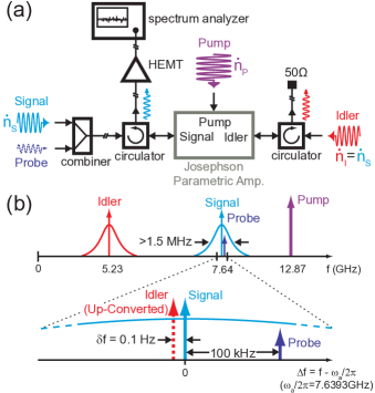
The JPC, operated at mK in a cryogen-free dilution refrigerator, has three ports (Fig. 1(a)), one each to access the signal (centered around GHz), idler (centered around GHz), and pump (at GHz) modes. Cryogenic circulators on the signal and idler ports separate input and output waves, allowing them to travel on different transmission lines (see Bergeal et al. (2010b) and Abdo et al. (2011) for details on the setup). Four phase-locked microwave generators provide tones to the signal port (signal and probe tones), the idler port (idler tone), and the pump port (pump tone). Incoming signal, idler, and pump photon fluxes are designated by , , and , respectively. We monitor in time the JPC signal port output power through a spectrum analyzer (SA) set to zero span mode, i.e. set to a frequency window given by the spectrum analyzer’s resolution bandwidth (RBW) and center frequency. The additional small amplitude probe tone used to measure gain modulation is offset from the JPC signal center frequency by kHz (Fig. 1(b)), which allows its detection with the SA without contamination from the large amplitude signal tone at the center of the JPC signal band, as long as the RBW of the SA is set to be much smaller than kHz. Both the signal and the probe tone are well within the amplification bandwidth of the JPC, which is MHz at a gain of dB, and which increases at smaller gains according to the gain bandwidth product Bergeal et al. (2010a), where is the power gain and the dynamical amplification bandwidth (in Hz).
The coherent cancellation effect is observed simply by injecting coherent signal and idler tones (with no probe tone at this stage) with the correct relative phase so that they destructively interfere, leading to a strong attenuation of the corresponding output tones by a factor determined by the gain of the amplifier. The effect is described by the linear two-port scattering matrix of the undepleted pump approximation: From the reduced JPC scattering matrix Bergeal et al. (2010a)
| (2) |
where is the (undepleted) gain of the amplifier when only a weak signal tone is present and is the pump phase. This phase will be kept fixed in the subsequent analysis and can be set equal to without loss of generality, although it should be emphasized that CC is a three wave, nonlinear interference effect, and can be modulated with the pump phase as well as the relative phase of signal and idler. The eigenvalues of this S-matrix are reciprocals: , the former corresponding to power amplification and the latter to power attenuation at large gains. If is the signal amplitude (corresponding to photon flux ), the eigenvectors are , requiring a balanced idler input (), either in phase or out of phase. The usual situation, when only the signal tone is sent in, corresponds to an equal superposition of the two eigenvectors, and only the amplification mode can be observed. If balanced beams with relative phase are input, the normalized output power, , (where are the signal output and input power) is given by
| (3) |
varying between increased gain and strong attenuation (). As the amplifier approaches the oscillation threshold, and the cancellation becomes perfect Longhi (2011). This effect is similar to the time-reversed laser operation in a coherent perfect absorber (CPA) Chong et al. (2010); Wan et al. (2011). Contrary to a CPA however, here the two input beams have different frequencies, and instead of absorption to an unspecified dissipative sink, here the input photons are converted into pump photons at their sum-frequency.
To observe CC in the JPC we slowly vary the phase between signal and idler input tones at a rate of Hz, by offsetting the idler tone above the JPC idler mode center frequency by Hz. The parametric amplification process up-converts and amplifies the idler tone, which, as a result of the detuning, appears below the amplified signal tone. To be able to monitor the power at the signal port in time with sufficient resolution of the phase , we set the SA to a RBW that is faster then the detuning : Hz when observing the attenuation of the signal tone and Hz when monitoring the probe gain 111We chose to present these two data sets as this is where we best achieved the balance between signal and idler photon flux.(see Supplemental Material at [URL will be inserted by publisher] for choice of bandwidths and detunings).
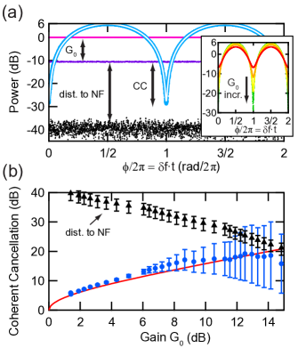
Fig. 2 shows the CC of the input signal tone, for signal and idler input powers well below (at least dB) the dB amplifier compression point Pozar (1997). The light blue trace is the measured, normalized signal output power , as function of the relative phase between signal and idler. In addition, the data is fit to Eq. 3 which is then plotted as the overlaid white curve; the single fit parameter, dB agrees well with its independently measured value. As noted, at large gains, and , , the wave amplitudes interfere constructively to produce a normalized power output dB (factor of ) above the signal output power with idler tone off (, pink trace). CC manifests itself at relative phase , when only a fraction of the incident power leaves the JPC through the signal and idler ports (normalized power ). The data in the inset in Fig. 2(a) shows for increasing , confirming this behavior.
The coherent cancellation is a measure of the efficiency of the conversion of signal and idler photons into pump photons. Fig. 2(b) shows that there is good agreement between our data (blue dots) and the prediction of Eq. 3 (red) for all gains up to the experimental limit imposed by the system noise floor (black triangles; see arrow labeled ‘dist. to NF’ in Fig. 2(a)). All error bars are calculated from the noise floor data according to the Dicke radiometer formula Dicke (1946). The increase for the CC data at larger gains is due to the fact that we systematically decrease the signal and idler tone powers at larger gains to make sure to stay well below the saturation point of the device (we keep approximately constant while ensuring that we exactly have ). This leads to a decrease in signal-to-noise ratio (SNR), as the JPC noise (and thus the system noise) increases with . A more serious limitation to the CC measurement is the fact that the noise floor (black trace in Fig. 2(a)) is pushed up when increases, while the input signal is adjusted to decrease. This means that our ability to observe the CC effect decreases for increasing gains (see ‘dist. to NF’ in Fig. 2(b)). This could of course be improved by reducing the RBW of the spectrum analyzer (pushing down the noise floor), but at the expense of having to perform the experiments slower by the same factor to keep the current phase resolution, which would make it more sensitive to 1/f noise and phase drifts.
The coherent cancellation effect as described by Eq. 3 is easily calculated in the undepleted pump approximation, but it is more general and still applies in the regime of larger signal and idler relative to the pump, when the depletion or enhancement of the pump is significant. The gain modulation effects in this regime provide a method to confirm that the attenuated signal and idler photons at the CC condition are not lost to some other dissipative process, but are being coherently converted to pump photons. Specifically, as the relative phase, of the signal and idler is varied, and the JPC is alternatively amplifying and attenuating these inputs, the pump is either depleted or strengthened, and this can be observed as a phase dependent modulation of the effective gain experienced by the weak probe tone, which we now introduce.
Experimentally, we keep the signal and idler photon fluxes equal () but in contrast to the experiment of Fig. 2, with signal and idler amplitudes large enough to significantly saturate the device. Eq. 3 still holds, with the undepleted gain, replaced by a nonlinear gain, , , which must be calculated self-consistently.
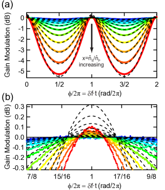
Fig. 3(a) shows the expected large modulation of the gain with , and, most dramatically, around (see Fig. 3(b)), we observe an increase in the JPC gain; moreover, the gain enhancement increases as we increase in dB steps (colors from blue to red). The data set shown corresponds to an undepleted gain of dB (normalized to dB line), and an applied pump power that is not changed across traces. Note that the gain enhancement , whereas the gain depletion , so one expects the enhancement to be smaller than the depletion.
We can calculate by solving the equations of motion derived from the three-wave mixing Hamiltonian (Eq. 1) iteratively in the correction to the undepleted pump approximation (see Supplemental Material at [URL will be inserted by publisher] for details on derivation). This leads to the self-consistent equations for the pump parameter :
| (4) | |||||
| (5) |
where is the undepleted pump parameter, and is the undepleted gain (no signal/idler inputs). The dashed lines in Fig. 3 correspond to theory with a single fit parameter . As expected, the fits reproduce the dB steps of applied signal and idler powers (not shown). We find excellent agreement between our theory and our experiment for phases away from , where signal and idler fields constructively interfere and lead to a depletion of the pump photon flux, manifested as a decrease of the JPC gain.
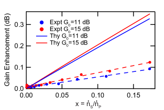
Figure 4 shows a direct comparison of the experimental gain enhancement to the theoretical prediction at as a function of for gains of dB and dB. Although the experimental slope is about of the expected theoretical slope, we unambiguously observe significant gain enhancement in our JPC, the key signature of the coherent conversion of signal and idler photons into pump photons. There are several reasons for the discrepancy between experimental and theoretical gain enhancement: the experiment requires significant averaging with the given bandwidths and powers (ultimately limited by the JPC dynamical bandwidth and dynamic range), while each modulation is rather slow ( Hz). It is thus sensitive to 1/f noise and microwave generator phase drifts. Further, any mismatch between and decreases the gain enhancement. Finally, there may be a contribution due to spurious dissipation in the CC process.
The presented gain enhancement results can be understood as a benchmark for the level of control we have over all degrees of freedom in our three-wave mixing device. Any hidden (uncontrolled) degree of freedom other than the signal, idler, and pump modes will inevitably be perceived as dissipation and thus lead to a reduction in the gain enhancement effect. A potential application of the reverse operation of a JPC is its use in phase-locking two coherent tones of different frequencies in a feedback loop, which could be crucial for quantum information processing with artificial atoms.
Discussions with Hui Cao are gratefully acknowledged. This research was supported by IARPA under grant W911NF-09-1-0369, ARO under grant W911NF-09-1-0514 and NSF under grants DMR-1006060 and DMR-0653377. A. D. S. acknowledges support by NSF under grant ECCS-1068642. Facilities used were supported by Yale Institute for Nanoscience and Quantum Engineering and NSF MRSEC DMR 1119826.
References
- Franken et al. (1961) P. A. Franken, A. E. Hill, C. W. Peters, and G. Weinreich, Phys. Rev. Lett. 7, 118 (1961).
- Aspect et al. (1981) A. Aspect, P. Grangier, and G. Roger, Phys. Rev. Lett. 47, 460 (1981).
- Kwiat et al. (1995) P. G. Kwiat, K. Mattle, H. Weinfurter, A. Zeilinger, A. V. Sergienko, and Y. Shih, Phys. Rev. Lett. 75, 4337 (1995).
- Louisell (1960) W. Louisell, Coupled mode and parametric electronics (Wiley, 1960).
- Longhi (2011) S. Longhi, Phys. Rev. Lett. 107, 033901 (2011).
- Bergeal et al. (2010a) N. Bergeal, R. Vijay, V. E. Manucharyan, I. Siddiqi, R. J. Schoelkopf, S. M. Girvin, and M. H. Devoret, Nat. Phys. 6, 296 (2010a).
- Abdo et al. (2012a) B. Abdo, A. Kamal, and M. H. Devoret, Fluctuating Nonlinear Oscillators: From Nanomechanics to Quantum Superconducting Circuits, edited by M. Dykman (OUP Oxford, 2012) pp. 119–141.
- Castellanos-Beltran et al. (2008) M. A. Castellanos-Beltran, K. D. Irwin, G. C. Hilton, L. R. Vale, and K. W. Lehnert, Nat. Phys. 4, 928 (2008).
- Bergeal et al. (2010b) N. Bergeal, F. Schackert, M. Metcalfe, R. Vijay, V. E. Manucharyan, L. Frunzio, D. E. Prober, R. J. Schoelkopf, S. M. Girvin, and M. H. Devoret, Nature 465, 64 (2010b).
- Hatridge et al. (2011) M. Hatridge, R. Vijay, D. H. Slichter, J. Clarke, and I. Siddiqi, Phys. Rev. B 83, 134501 (2011).
- Roch et al. (2012) N. Roch, E. Flurin, F. Nguyen, P. Morfin, P. Campagne-Ibarcq, M. H. Devoret, and B. Huard, Phys. Rev. Lett. 108, 147701 (2012).
- Hatridge et al. (2012) M. Hatridge, S. Shankar, M. Mirrahimi, F. Schackert, K. Geerlings, T. Brecht, K. M. Sliwa, B. Abdo, L. Frunzio, S. M. Girvin, R. J. Schoelkopf, and M. H. Devoret, Accepted for Publication in Science (2012).
- Abdo et al. (2011) B. Abdo, F. Schackert, M. Hatridge, C. Rigetti, and M. Devoret, Applied Physics Letters 99, 162506 (2011).
- Abdo et al. (2012b) B. Abdo, K. Sliwa, F. Schackert, N. Bergeal, M. Hatridge, L. Frunzio, A. D. Stone, and M. H. Devoret, In Preparation (2012b).
- Chong et al. (2010) Y. D. Chong, L. Ge, H. Cao, and A. D. Stone, Phys. Rev. Lett. 105, 053901 (2010).
- Wan et al. (2011) W. Wan, Y. Chong, L. Ge, H. Noh, A. D. Stone, and H. Cao, Science 331, 889 (2011).
- Note (1) We chose to present these two data sets as this is where we best achieved the balance between signal and idler photon flux.
- Pozar (1997) D. Pozar, Microwave engineering (Wiley, 1997) p. 549.
- Dicke (1946) R. H. Dicke, Review of Scientific Instruments 17, 268 (1946).