Properties of the band gaps in one-dimensional ternary lossy photonic crystal containing double-negative materials
Abstract
In this paper, theoretically, the characteristics matrix method is employed to investigate and compare the properties of the band gaps of the one-dimensional ternary and binary lossy photonic crystals which are composed of double-negative and -positive materials. This study shows that by varying the angle of incidence, the band gaps for TM and TE waves behave differently in both ternary and binary lossy structures. The results demonstrate that by increasing the angle of incidence for the TE wave, the width and the depth of zero-, zero-, and Bragg gap increase in both ternary and binary structures. On the other hand, the enhancement of the angle of incidence for the TM wave, contributes to reduction of the width and the depth of the zero- and Bragg gaps, and they finally disappear for incidence angles greater than and for the binary structure, and and for the ternary structures, respectively. In addition, the details of the edges of the band gaps variations as a function of incidence angle for both structures are studied.
I Introduction
Photonic crystals (PCs) are artificial dielectric or metallic structures in which the refractive index changes periodically. The periodic structure of the PCs contributes to photonic band gap (forbidden range of frequencies). Interference of the Bragg scatering is considered as a cause of this phenomena. PCs have attracted much interest due to their novel electromagnetic waves characteristics and important scientific and engineering applications and have received attentions by many researches in recent decades re1 ; re2 ; re3 ; re4 ; re5 ; re6 ; re7 ; re8 . With possibility of producing metamaterials, PCs containing metamaterials, namely “Metamaterial Photonic Crystals” (MPCs) have been made. The technological relevance of the MPCs is of great importance. These structures have attracted considerable attentiom for their various applications. Designing dielectric mirrors, effective waveguides, filters, and perfect lenses are clear cut examples. The metamaterials are utalized to design binary and ternary MPCs with layers of Double Negative (DNG) and Double Positive (DPS) materials. In these structures, various band gaps can be seen in the transmission spectrum. When the average refractive index of the MPC is equal to zero, the band gap is called zero- gap re9 . The properties of the zero- gap of one-dimensional (1D) binary MPC that composed of the two layers of DNG and DPS materials were investigated in recent years re9 ; re10 ; re11 ; re12 ; re13 ; re14 ; re15 ; re16 . In 1D binary PMC, in addition to the zero- and Bragg gaps, we also have zero- and zero- gaps for TE and TM waves respectively, which appear for the oblique incidence angles. The results have been also reported by some authors re16 ; re17 ; re18 .
The novel idea of this research is to include the loss factor which is an unavoidable consequence of Double Negative materials to investigate optical properties of 1D binary and ternary MPCs. In this regard the transmission of electromagnetic waves through a 1D ternary lossy PC consisting of layers with double-negative and -positive materials is studied. The effects of the incidence angle and polarization on the characteristics of the zero-, zero-, zero-, and Bragg gaps are investigated. Furthermore, the results are compared with the similar results in the 1D binary lossy PC.
The paper is organized as follows: the MPC structures design, the permittivity and permeability of the DNG layer, and theoretical formulation (characteristic matrix method) are described in Section 2, the numerical results and discussions are presented in Section 3, and the paper is concluded in Section 4.
II Structures design and characteristic matrix method
The 1D MPC structure under study which is located in air is constituted by alternative layers of DNG and DPS materials, where the DNG material is dispersive and dissipative. We consider the 1D binary MPC with periodic structure of and the 1D ternary MPC with periodic structure of , where A, B, and C denote three different materials. N is number of the lattice period and , , and are thickness, permittivity and permeability of the layers, respectively.
The permittivity and permeability of the DNG (layer A) in the microwave region are complex and are given as re9 ,
| (1) |
| (2) |
where f and are frequency and damping frequency, respectively, given in GHz. Various details of the real parts of the permittivity and permeability of layer A, versus frequency have been discussed in our previous work re10 .
The calculation is based on the characteristic matrix method re19 , which is most effective to analyze the transmission properties of PCs. The characteristic matrix for TE wave at incidence angle from vacuum to a 1D PC structure is given by re19 :
| (3) |
where and for binary and ternary PCs, respectively. , c is speed of light in vacuum, is the angle of refraction inside the layer with refractive index and is given as:
| (4) |
where
| (5) |
The characteristic matrix for N period structure is therefore . The transmission coefficient of the multilayer is given by:
| (6) |
where are the matrix elements of , and
| (7) |
The transmissivity of the multilayer is given by:
| (8) |
The above formulations can be applied for TM wave by simple replacements of , , and as follows:
| (9) |
| (10) |
III Numerical results and discussion
Based on the theoretical model described on the previous section, the transmission spectrum of the presented lossy MPC structures was calculated. In the study of the 1D binary MPC, consisting of DNG (layer A) and DPS (layer B) materials, equations (1) and (2) are used for the permittivity, , and the permeability, , of layer A. Layer B is assumed to be a vacuum layer with . The thickness of layers A and B are chosen as mm and mm, respectively and the total number of lattice periods is set as re10 .
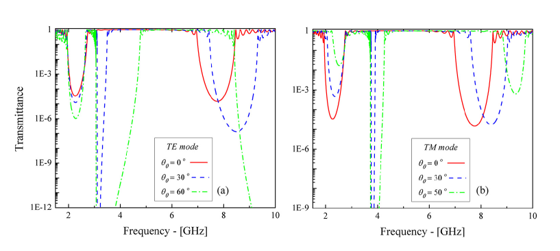
The transmission spectra of TE and TM polarized waves for the binary structure at various angles of incidence and for GHz are shown in Figs. 1(a) and 1(b), respectively. For oblique incidence the zero- and zero- gaps appear in the transmission spectrum for TE and TM waves, respectively, as reported in re17 ; re18 . The gaps appear at the frequencies where the sign of the permeability or permittivity of DNG materials changes. As it is seen in Fig.1 the width of the gaps increases as the incidence angle increases while the left edge of the gaps remain nearly unchanged. In addition, for TE waves the width and the depth of the zero- and the Bragg gap increase as the incidence angle increases, as reported in re9 ; re10 ; re11 ; re12 ; re13 ; re14 . On the contrary, for TM waves the width and the depth decrease as the incidence angle increases (Fig. 1(b)). Moreover, the figures show that the central frequency of the zero-, as reported in our previous work re10 , and the Bragg gap shift to the higher frequencies as the angle of incidence increases.
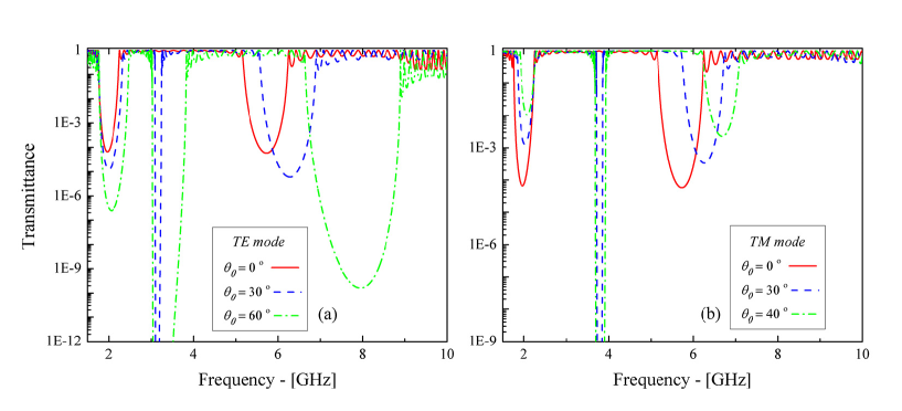
In the next part, the band gaps of the 1D ternary MPC are investigated. The binary structure used before, is modified by introducing a third layer of (layer C) with refractive index of and thickness of mm in each lattice period. The other parameters are kept the same as in the binary structure. The transmission spectra of TE and TM polarized waves for the ternary structure at various angles of incidence and for GHz are shown in Figs. 2(a) and 2(b), respectively. As it is seen, the width of the zero- and zero- gaps increases by increasing the incidence angle. Although, for TE wave the width and the depth of the zero- and the Bragg gaps increases as the incidence angles increases. For TM waves the behaviour is completely different, such that the width and the depth of the band gaps decrease when the angle of incidence increases. However, the central frequency of the zero- and Bragg gaps behave the same as in the binary structure where they shift to the higher frequencies as the angle of incidence increases.
In this part the band gaps in binary and ternary structures are compared. As it is seen from, Figs. 1 and 2, the width of the band gaps decreases, when another dielectric layer added to the lattice period of binary structure. Furthermore, the zero- and Bragg gaps frequencies of the ternary structure are lower the corresponding frequencies in the binary structures; while the zero- and zero- gaps appears in the same frequencies in both structures.
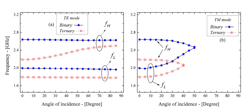
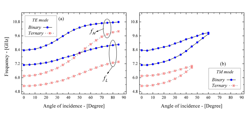
The lower () and higher () frequencies of the zero- gap in the binary and ternary structures, as a function of incidence angle for TE and TM waves are shown in Figs. 3(a) and 3(b), respectively. As it is clearly seen, the lower frequency of the gap for the ternary structure is smaller than that in the binary structure for both TE and TM modes for different incidence angles. It is also interesting to note that the width of the gap in the ternary structure for TE wave is sensitive to the angle of incidence and increases as the incidence angle increases while the left edge of the band gap is nearly invariant. Moreover, the width of the zero- gap of both binary and ternary structures is very sensitive to the incidence angle for TM wave, and the gap disappears for incidence angles greater than in the binary structure as reported in [10,12]. The gap disappears for incidence angles greater than for the ternary structure.
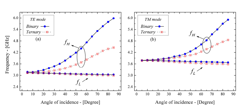
The lower and the higher frequencies of the zero- and zero- gaps as a function of incidence angle, for both binary and ternary structures are shown in Figs. 4(a) and 4(b), respectively. The width of the zero- and zero- gaps increases faster for the binary structure than the ternary ones. As it is clearly seen, the gaps appears at the same frequency for both binary and ternary structures; in addition, the figures indicate that the upper edge of the gaps, so the width of the gaps, are very sensitive to the incidence angle while the lower edge of the gaps are nearly insensitive.
The and frequencies of the Bragg gap of the binary and ternary structures, as a function of incidence angle for TE and TM waves are shown in Figs. 5(a) and 5(b), respectively. It is seen that the Bragg gap like the zero- gap appears in the lower frequencies for the ternary structure. Moreover, and shift to the higher frequencies as the incidence angle increases, and as it is seen from Fig. 5(b), the gap for TM polarized wave disappears for incidence angles greater than for the binary and for the ternary structures.
IV Conclusion
The numerical results show that including the loss factor in the permittivity and permeability of the DNG layer the changes in transmission spectrum of TE wave in 1D ternary and binary PMCs behave similarly for different incidence angles. The zero- and zero-, and the Bragg gaps become wider and dipper as the angle of incidence increases. In addition, by enhancing the angle of incidence, the lower frequencies of the zero- and zero- gaps are nearly invariant in both ternary and binary PMCs, but the Bragg gap increases. Moreover, the upper edge of all three band gaps increases. Such behaviors do not clearly observed in the zero- gap. The transmission spectrum for TM polarized wave is rather different. It is found that in both structures, as the angle of incidence increases, the width and the depth of the zero- gap increase, while for the zero- gap and for the angles of incidence greater than for the ternary and for the binary structures the zero- gap disappears. Similar behavior is observed for the Bragg gap for the angles of incidence greater than and for binary and ternary structures, respectively. For TM waves, the lower frequency of the zero- and Bragg gaps increases, but the zero- gap decreases as the angle of incidence increases in both binary and ternary structures. The higher edge of the zero- and Bragg gaps increases while it decreases for the zero- gap. It is interesting to note that the difference between the lower and higher frequencies of all the gaps for TM wave in the binary PMC, is larger than that in the ternary PMC as all the figures show. To recapitulate what was said before, i- the width of the band gaps decreases as a dielectric layer is added to the binary structure. ii- the zero- and Bragg gaps appear at the lower frequencies in the ternary structure. iii- the zero- and zero- gaps appear at the same frequencies in both structures. Finally, the results of the present study could be employed in designing new edge filters, waveguides, and other optical devises in microwave engineering.
References
- (1)
References