Performance of transducers with segmented piezoelectric stacks using materials with high electromechanical coupling coefficient
Abstract
Underwater acoustic transducers often include a stack of thickness polarized piezoelectric material pieces of alternating polarity interspersed with electrodes, bonded together and electrically connected in parallel. The stack is normally much shorter than a quarter wavelength at the fundamental resonance frequency, so that the mechanical behavior of the transducer is not affected by the segmentation. When the transducer bandwidth is less than a half octave, as has conventionally been the case, stack segmentation has no significant effect on the mechanical behavior of the device. However, when a high coupling coefficient material such as PMN-PT is used to achieve a wider bandwidth, the difference between a segmented stack and a similar piezoelectric section with electrodes only at the two ends can be significant. This paper investigates the effects of stack segmentation on the performance of wideband underwater acoustic transducers, particularly tonpilz transducer elements. Included is discussion of transducer designs using single crystal piezoelectric material with high coupling coefficient compared with more traditional PZT ceramics.
Applied Research Laboratory MS2430, The Pennsylvania State University, State College, Pennsylvania 16804-0030
Suggested running title: high segmented piezoelectric stacks
submitted: January 30, 2013
PACS numbers: 43.38Fx, 43.378Ar
Keywords: piezoelectric
1 Introduction
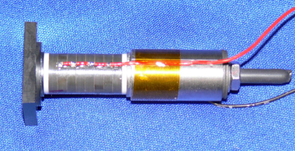
Transducers based on piezoelectric ring stacks were conceived by Miller [1] and have been used at least since 1959. Since then, piezoelectric sonar transducers are often constructed using a stack of thickness-polarized piezoelectric rings or plates. An example of such a transducer is shown in Figure 1. The segmentation of the piezoelectric material into rings or plates may be done to facilitate the manufacturing and polarization of the piezoelectric pieces and/or to reduce the voltage needed to achieve the electric field required for full output power. In either case, the stack is assembled by alternating the polarization directions of adjacent rings in the stack, and alternating the voltages on the electrodes between the rings. The rings are stacked mechanically in series, but wired electrically in parallel. In this way, at least for quasistatic operation, all of the piezoelectric pieces are driven to expand and contract simultaneously.
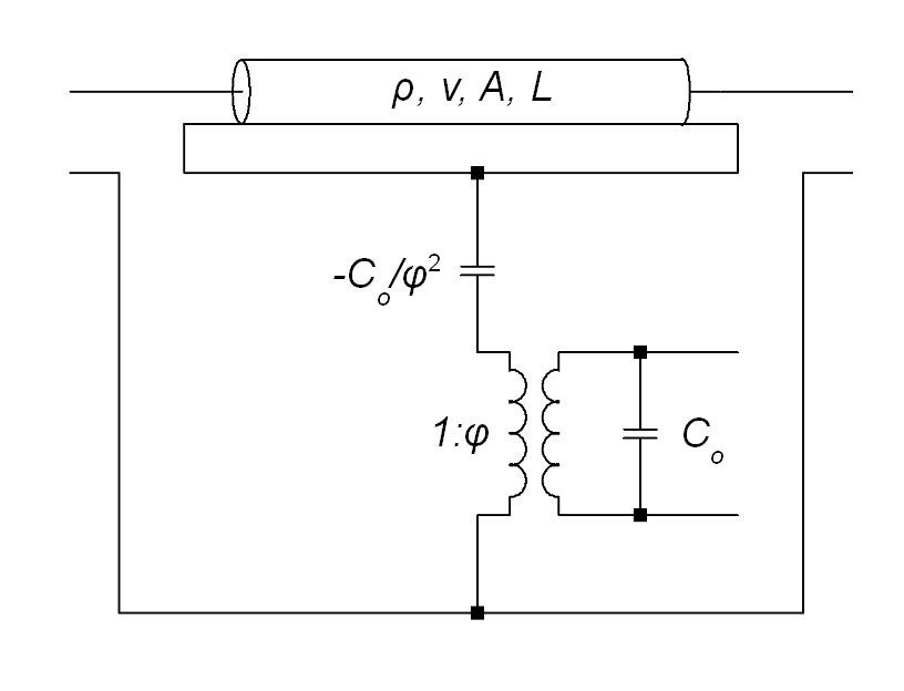
The first description of a ring stack assembly is by Miller[1]. Previously, Mason had introduced a method of analysis and an analog circuit for individual piezoelectric plates and tubes, initially using a lumped parameter analog circuit [2] and later allowing longitudinal plane wave motion in the piezoelectric piece [3]. Redwood [4] recognized that the mechanical domain in the Mason analog circuit could be represented as a mechanical transmission line. Figure 2 shows the Redwood implementation of the Mason analog circuit for a single piezoelectric piece. Martin was the first to analytically describe the operation of the segmented stack. He first provided an analysis of the performance of longitudinally polarized piezoelectric tubes that includes effects of axial stress in the tube walls [5]. He then described the analysis of the ring stack as an assembly of short tubes or rings with their mechanical ports connected in cascade and their electrical ports connected in parallel [6, 7].
The conclusion of the Martin analysis is that a piezoelectric stack of identical rings, each of length
-
1.
has the mechanical behavior identical to that of a single long tube of length with slightly modified material parameters, and
-
2.
has the electrical behavior consistent with the short rings wired electrically in parallel.
Martin stated that his analysis assumes only that the rings have identical dimensions and material properties, and that the length of each ring is much less than a half wavelength in the piezoelectric material, . These conclusions significantly simplify the design process for a tonpilz transducer. The projector designer can select the total stack length to provide sufficient dynamic displacement, and can separately determine the total number of rings in the stack to assure the producibility of the rings, and to obtain an appropriate electrical impedance that keeps the drive voltage level required for full power operation to a moderate level. Wilson [8] and Stansfield [9] each give an example of the use of the Martin conclusions. The unstated assumption of both authors is that the segmentation of the piezoelectric stack does not affect the mechanical behavior of the transducer.
Despite the acceptance and utility of the Martin conclusions, the Appendix shows that there is both an error and an omission in the Martin derivation that have been previously unrecognized, probably because they introduce negligible error in the calculation when used with materials that have an electromechanical coupling coefficient less than about 0.75. That includes all of the piezoelectric materials that were available to Martin, Wilson, Stansfield and others at the time of their work. In the next section, however, those errors will be shown to be important when using single crystal piezoelectric materials that have electromechanical coupling coefficient higher than 0.75, particularly when those materials are used to implement transducers with higher power and wider bandwidth than is possible with PZT and other conventional piezoelectric materials.
The error in Martin is his claim that his approximation holds whenever the length of the individual ring in the stack is small, . The appendix shows that it is the total length of the stack, rather than the length of the individual ring, that must be small. For a stack of pieces, the requirement is that . By itself, that is not a serious limitation, as most designers would expect the total stack length to be significantly less than a wavelength in all cases, in order to maintain a sufficient frequency separation from the first “higher mode” mechanical resonance within the stack. However, that situation needs to be reexamined in light of the significant bandwidth that may be available with high coupling coefficient piezoelectric materials.
The omission in Martin is the recognition from Equation 15 in the Appendix that the error in the approximation is proportional to . This means that the length constraint is relatively more important when either the coupling coefficient or the number of stack segments is high.
Of course, all of the statements above are qualitative and cautionary, but provide no information on the limits of the approximation in any specific case. The balance of this paper shows the effect on the analysis of the particular transducer shown in Figure 1.
The effects of stack segmentation on transducer performance will be shown below, both analytically and with data from the transducer shown in Figure 1. The effects are apparent in an analog transmission line model within the limitations of accuracy of such a model.
Note that the information in this paper should not be interpreted as a negative report on materials with high electromechanical coupling. Materials with high coupling enable transducer designs that are difficult or impossible to achieve with other piezoelectric materials[10, 11]. The relevant point is that the design methods and design intuitions that have served well in the past may need to be revised to take full advantage of properties of the new materials.
2 Analysis
The initial calculations of the element performance will be shown with an analog circuit model using plane wave transmission lines to model the mechanical properties of the piezoelectric stack. While the longitudinal models are not sufficient to fully describe the behavior of the transducer hardware, they do clearly show the effects of segmentation and are a simpler framework for understanding the effects. A full FEA of the transducer is then used to include the full three dimensional effects and for comparison with the experimental hardware.
2.1 Analysis Using a Plane Wave Model
The initial calculations of the element performance will be shown using an analog plane wave model implemented in the SPICE [12, 13] computer code using methods that were first described by Leach [14, 15]. Each material piece in the transducer assembly is modeled as a mechanical transmission line with constant area. Electromechanical coupling in the piezoelectric material is modeled with controlled sources in SPICE in the manner described by Leach [15]. The interconnections of material pieces follow the conventions of analog circuits using the impedance analogy. The present work has been performed using the LTspice code[16], although several other SPICE versions are known to be suitable[17].
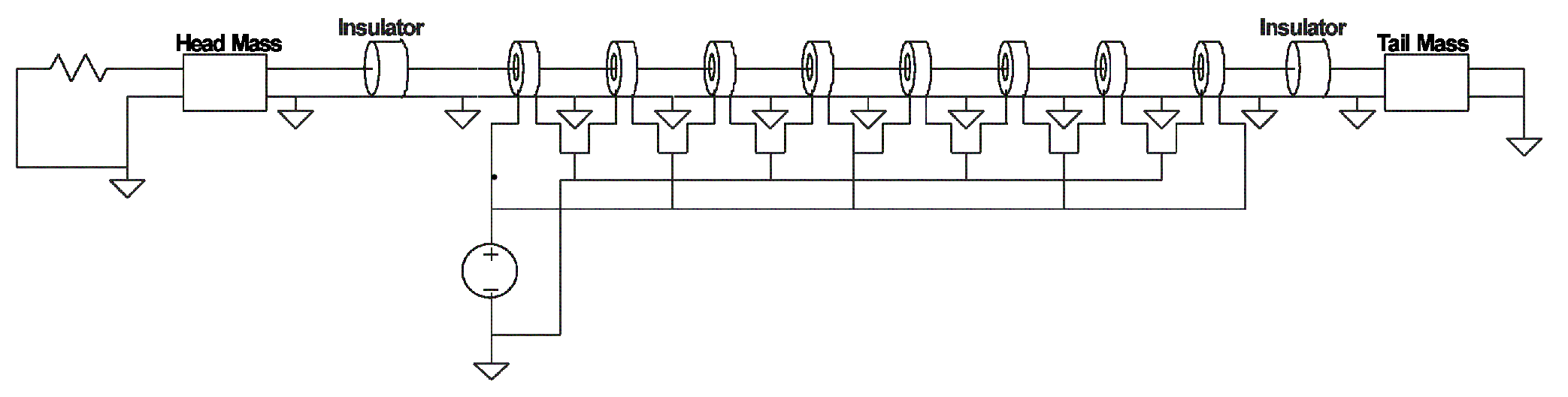
The simplified transducer model is shown in Figure 3. This shows the interconnection of the mechanical pieces and the electrical terminals of the transducer in a schematic-like graphic. The eight piezoelectric rings at the center of the diagram are modeled individually using the Leach [15] implementation of the Redwood [4] analog circuit to avoid any possibility of errors in the Martin approximation described in the Appendix being present in this analysis. A thin insulator is placed at each end of the piezoelectric stack. The head and tail masses are connected to the insulators at opposite ends of the stack. The head mass is terminated with a radiation resistance whose value is , where is the density of the medium, is the sound speed in the medium, and is the radiating area. This is a reasonable approximation if the element is used in a large array. The back end of the tail has a zero force boundary condition, analogous to an electrical connection to zero potential. The full analog circuit implementation also includes a large number of ground terminations in the electrical and mechanical domains to meet the SPICE requirement that every circuit loop have a DC reference to ground.
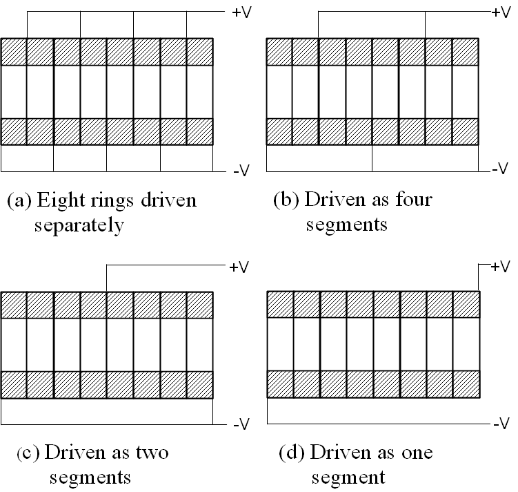
For comparison, three other transducer designs were also analyzed, with the piezoelectric section segmented into four pieces, two pieces, and one piece as shown in 4. In each case, the individual piece length in the model was adjusted so that the total length of the piezoelectric stack is the same as the length of the eight piece stack in the model of Figure 3. The electrical connection of the piezoelectric rings is in parallel. The rings are assembled with alternating polarization directions, so that they are all driven to expand and contract in phase. Glue joints and electrodes are not included in the model. The small added compliance of the glue joints may explain a part of the difference in resonance and antiresonance frequencies between measurement and model that are seen in Section 2.2. A stress rod that is present in the transducer element is not included in the model at this stage of the analysis. In the actual transducer, the stress rod adds very little stiffness to the assembly because it is attached with a highly compliant spring washer at the tail.
The analysis described above was performed using piezoelectric material parameters for PZT-4 ceramic, and again using material parameters appropriate for the high coupling PMN-PT single crystal material. Values for the material parameters for this analysis were taken from Sherman and Butler [18]. The dimensions of the piezoelectric pieces with the two materials were the same, and no attempt was made to compensate for the difference in resonance frequency caused by the different mechanical properties of the two materials.
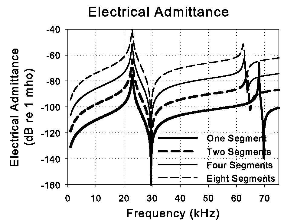
The electrical admittance curves calculated from the analog model with air loading for the four PZT-4 ceramic stacks are shown in Figure 5. The 12 dB level difference between curves at low frequencies is caused by the different segmentation levels of the stack. There is a factor of four difference in stack impedance when the number of rings is doubled and the ring thickness is halved. The resonance frequencies and the antiresonance frequencies calculated for the four transducers each differ by less than 0.5%. Note that at the second resonance, there is a noticeable difference in resonance frequency between the unsegmented case and all of the segmented cases. However, this difference is small enough that it would likely not be recognized unless the segmented and unsegmented curves were compared in this way, and even if it were noticed, it would not be considered important. In PZT transducers, the second resonance is always far enough above the primary resonance that it has no noticeable impact on the performance in the primary band.
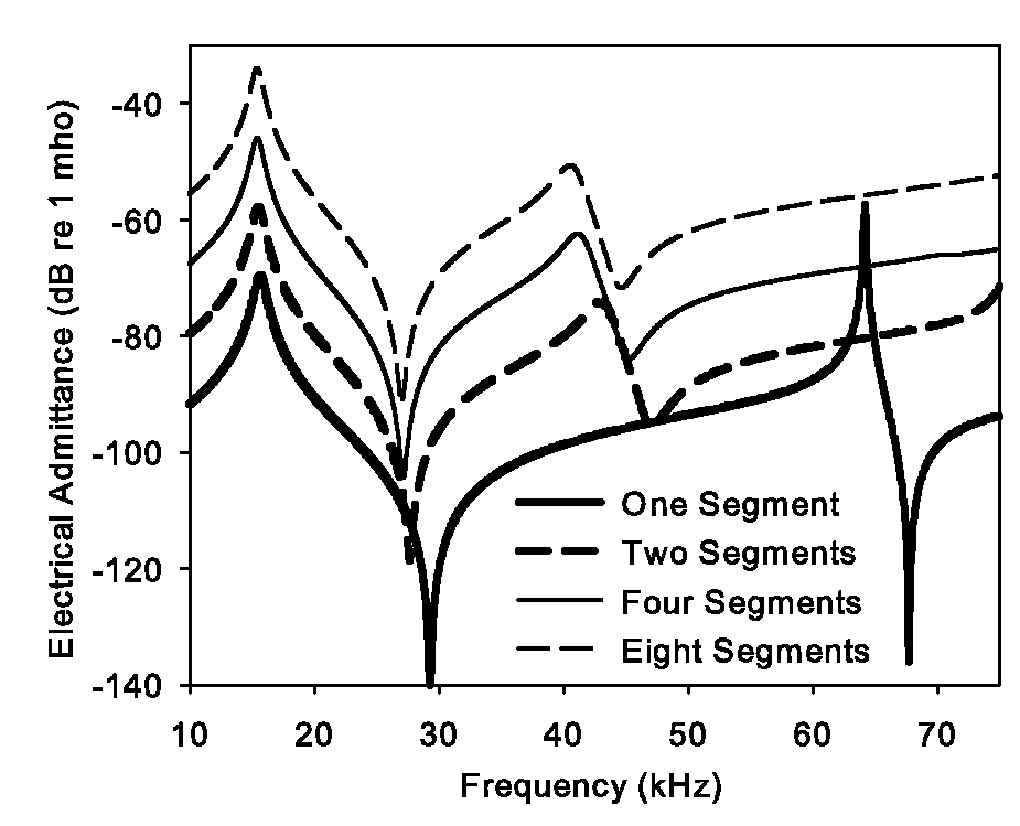
The electrical admittance curves with air loading for the four PMN-PT single crystal stacks are shown in Figure 6. The 12 dB level difference between curves at low frequencies is again present due to the segmentation. The calculated resonance frequencies of the four transducers do not vary significantly. However, the antiresonance frequencies differ noticeably, and the second mode resonance frequencies vary dramatically. Again, the difference is between the unsegmented piece and all of the segmented stacks. The change in antiresonance frequency reduces the effective coupling coefficient for the transducer with segmentation by a bit over 2%. The numerical values for these frequencies and the effective electromechanical coupling coefficient calculated from them are given in Table 1. The reduction in the frequency of the second mode resonance with segmentation is quite noticeable, now being less than a third octave above the antiresonance frequency. This difference may be considered important in some applications, as it may affect the operating bandwidth of the device. This will be seen by looking at the Transmitting Voltage Response (TVR).
The far field SPL for the element can be calculated approximately as
| (1) |
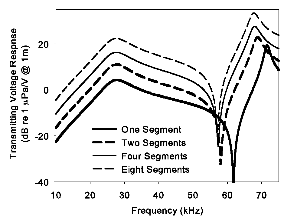
where is the area of the head, and is the measurement distance and is the radiating velocity of the head. Thus the approximate TVR for the element can be calculated from Equation 1 with , where the head velocity is calculated from the analog model using a 1 V drive signal. The TVR calculated in this manner with the radiation load of for the four implementations of the transducer using PZT-4 are shown in Figure 7. The difference in the level of the TVR is due to the different electric field in the piezoelectric material. For this calculation, a unit voltage is applied to the element terminals, but the different amounts of stack segmentation cause the voltage to be applied across piezoelectric pieces of different thickness. The low frequency level difference of 6 dB between adjacent curves is expected because the piezoelectric piece thickness differs by a factor of two.
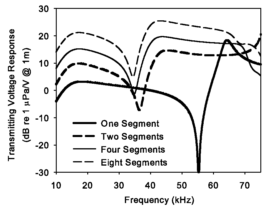
The TVR calculated in this manner with the radiation load of for the four implementations of the transducer using PMN-PT are shown in Figure 8. Again, the difference in the level of the TVR at low frequencies is due to the different electric field in the piezoelectric material. Using nearly any measure of operating bandwidth, the bandwidth available with the high coupling material is less when the stack is segmented than with the unsegmented stack.
Note that the fractional bandwidth with high coupling material, even with the segmentation, is still higher than the fractional bandwidth using PZT. Using the same definition of bandwidth, the PZT transducer may operate from 20 kHz to 40 kHz, while the PMN-PT transducer would operate from 10 kHz to 30 kHz. There may be additional advantages with the PMN-PT in that it operates with the same absolute bandwidth at a lower center frequency, and that the lower frequency operation is achieved with no increase in size. However, it remains true that high coupling material without segmentation has an even greater bandwidth with a relatively flat TVR.
| # Segments | 1 | 2 | 4 | 8 |
| Using PMN-PT with | ||||
| (Hz) | 15671 | 15520 | 15456 | 15434 |
| (Hz) | 29286 | 27650 | 27176 | 27044 |
| (Hz) | 0.845 | 0.828 | 0.823 | 0.821 |
| Using PZT with | ||||
| (Hz) | 27464 | 27388 | 27368 | 27368 |
| (Hz) | 35460 | 35239 | 35166 | 35142 |
| (Hz) | 0.633 | 0.629 | 0.627 | 0.627 |
2.2 Analysis with FEA
The previous predictions were based on a one dimensional model and show the character of the differences between moderate and high coupling materials with stack segmentation. However it does not model the fully realistic motion within the transducer that includes axial motion at least in the piezoelectric stack and the possibility of non-axially symmetric motions such as would occur with a flexural resonance in the head or other parts. The theory was extended to three dimensional modeling using the ATILA finite element code. The geometry created in the model matched the PMN-PT single crystal tonpilz element shown in Figure 1. The piezoelectric stack was modeled in two ways, first with eight rings having alternating polarity and wired as shown in Figure 4(a), and separately as a single piezoelectric piece wired as shown in Figure 4(d). Corresponding measurements on this tonpilz element were also done in two ways. First, the motor section was built using traditional methods with eight rings stacked with alternating polarity separated with electrode shims as in Figure 4(a). This stack configuration is labeled as “parallel” in the following figures as the rings are wired electrically in parallel. The stack configuration was then altered in such a way as to connect the rings in series. This was accomplished by reverse polarizing the even rings in the stack thereby providing a continuous polarity direction for the rings in the stack. The electrode tabs were then removed from the intermediate electrodes, and the electrical potential was applied across the stack as if it were one solid piece in Figure 4(d). This configuration is labeled “series” in the figures that follow and it is compared to a finite element simulation that models this geometry.
This “series” configuration of the stack is similar to the physical condition of a single piece, but not identical to it. A single piezoelectric piece, or a stack of rings with no metal electrode in place, would allow the electric potential to vary axially at the electrode positions. With the metal electrodes in place, the potential is held constant across this electrode surface. However the calculated results of the FEA model matched the conditions with the conductors in place, so the conditions during measurement are properly modeled. Furthermore, the effect of the open electrodes in the stack is not expected to be significant. The following section uses this model for the calculations that are compared with measurements on a single transducer element of Figure 1.
(a) parallel electrical connection
(b) series electrical connection
3 Verification with Measurement
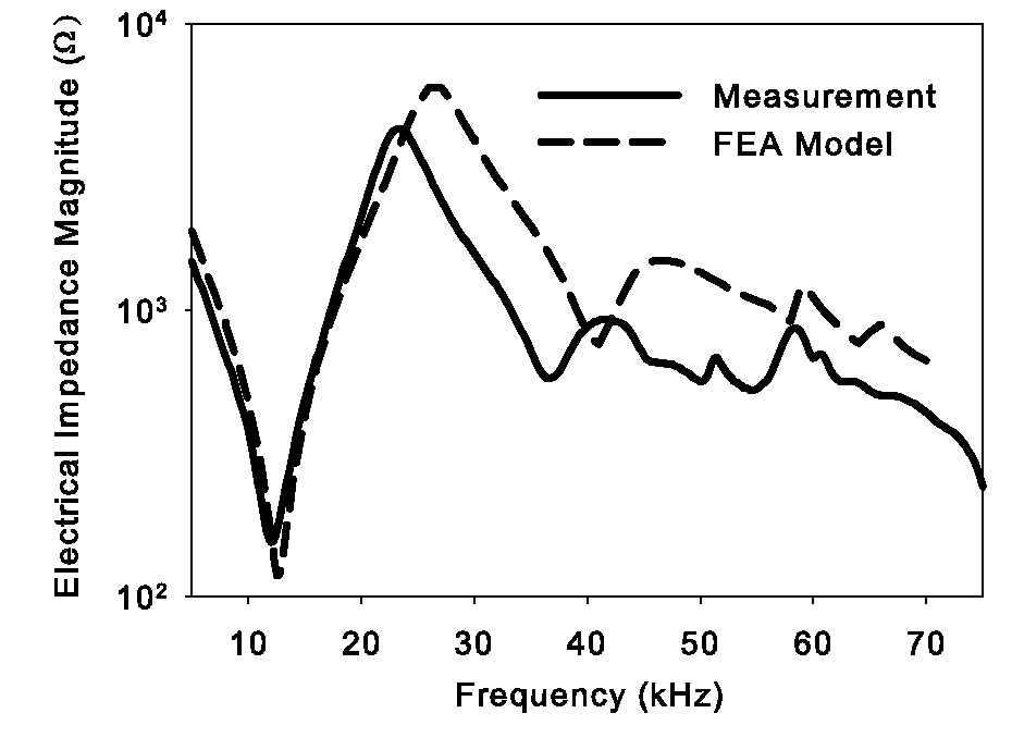
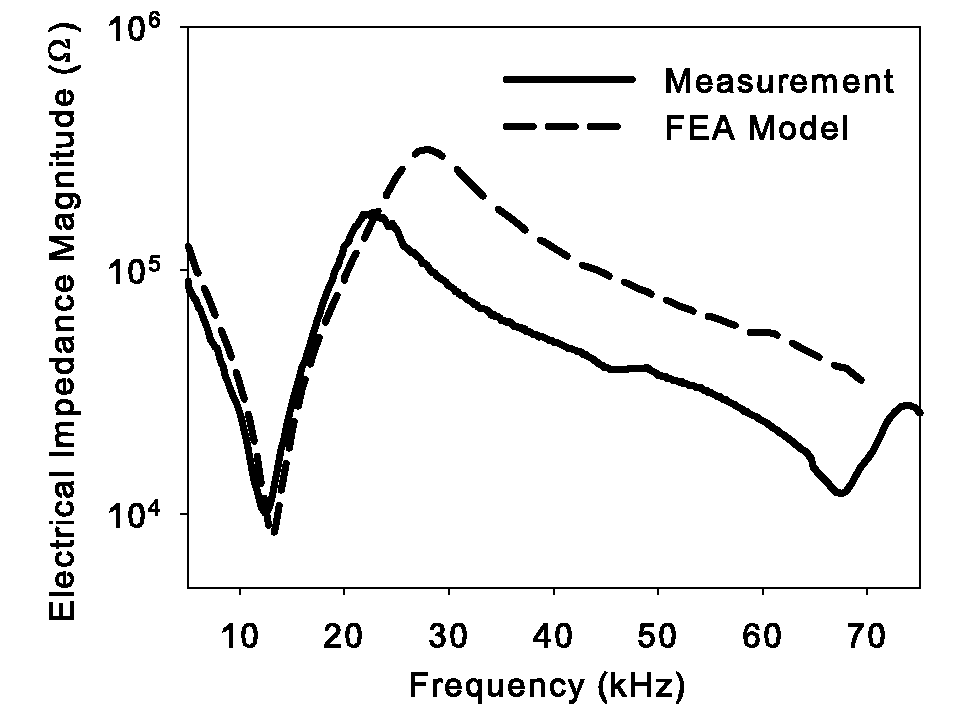
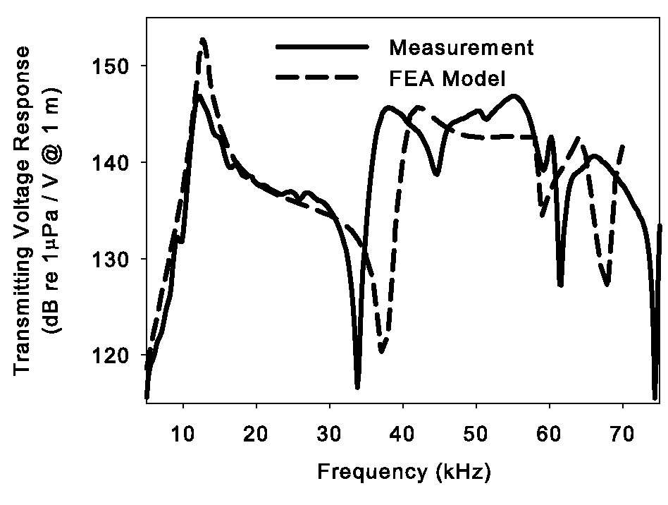
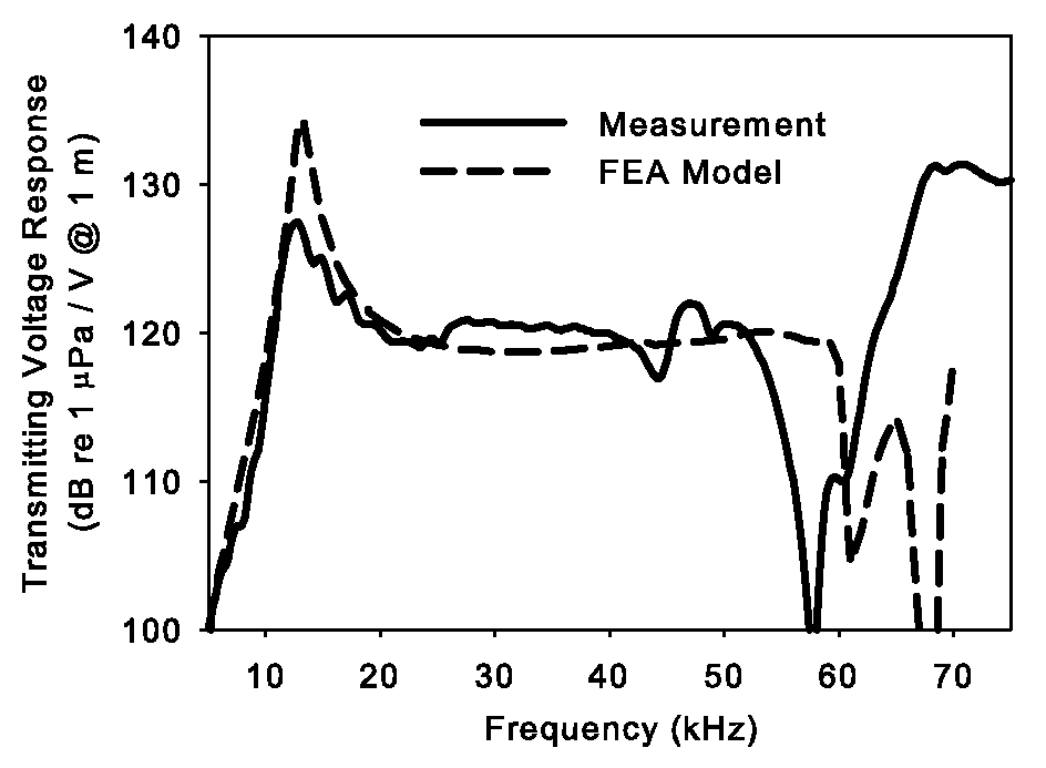
Figures 9 and 10 show the comparison of the model and measured results obtained for the parallel and series stack arrangements. Figure 9 is the electrical impedance magnitude for the element in water, and Figure 10 is the TVR. Note that the vertical scale difference between the parallel and series connections is a factor of 8 (18 dB) in the TVR and a factor of 64 the impedance, as expected with the 8-ring segmented stack. The results show a small improvement of the effective electromechanical coupling coefficient in the series arrangement. Even more dramatic is the difference in the higher frequency response. In the parallel arrangement, resonances are observed in the electrical impedance near 40 kHz. However, in the series experiments the next resonance is not observed until 68 kHz (see Figure 8). This is similar to the effect seen in Figure 6, although that figure does not include the effects of water loading on the response. A similar effect is seen in the TVR responses shown in Figure 10. Only minor differences are observed around the fundamental mode. However, a 24 kHz difference is observed in the location of the null in the TVR response.
(a)
(b)
The FEA model does not agree perfectly with the position of the second resonance in either the series or parallel configuration of the stack. Reasons for that difference include an imperfect knowledge of the piezoelectric parameters of the single crystal material, changes to the material parameters that occurred during the depolarization and repolarization to achieve the series connection, and the presence of glue joints in the transducer. The agreement with measurement is certainly good enough to understand that at least much of the performance difference is explained by the series vs. parallel connection of the piezoelectric rings.
4 Conclusions
This paper describes the effects of segmented stack design on the performance of transducers built with high coupling single crystal piezoelectric materials and compares those effects to a transducer built with traditional PZT ceramics. One dimensional and finite element models accurately predict the performance of the measured device. The models show the change in the effective electromechanical coupling coefficient of the complete transducer and the shifts in frequency of higher order modes when the stacks are systematically segmented into multiple pieces. Transducer designers using materials with high electromechanical coupling coefficient to meet requirements for the widest possible bandwidth should understand and consider these effects when developing designs using high coupling piezoelectric materials.
Appendix
In references [6, 7] Martin develops the conclusion that a ring stack of pieces each of thickness can be modeled as a single element with length with slightly modified material parameters. (see Figure 11) In his derivations, Martin requires only that ; e.g. that the length of each ring segment is much less than a half wavelength of vibrations in the piezoelectric material. This appendix will show that Martin’s conclusion actually requires that the length constraint be , and that further considerations are necessary when the electromechanical coupling coefficient of the piezoelectric material is higher than approximately 0.75.
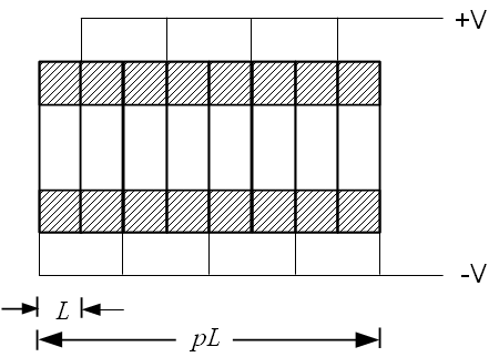
The constraint on the total length of the stack is generally understood to be required for good performance by transducer designers. When the stack length approaches a half wavelength, a mechanical resonance within the stack will severely degrade the transducer performance. Such long stacks would thus have been avoided in any case. Until recently, the unstated constraint on the electromechanical coupling coefficient was enforced by the fact that there were no available piezoelectric materials with higher coupling. The current availability of single crystal piezoelectric materials with electromechanical coupling coefficient greater than 0.85 allow the error in the Martin derivation to be seen.
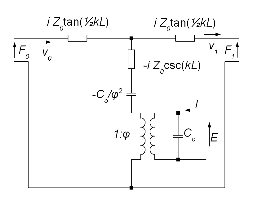
The Martin derivation correctly arrives at the 3-port model for a single piezoelectric ring as the analog circuit of Figure 12 where
| (2) | |||||
| (3) | |||||
| (4) | |||||
| (5) | |||||
| (6) |
and the equation for the impedance matrix described by this circuit is
with
| (7) |
where and are the mechanical force and velocity at the two ends of the piece, and and are the voltage and current at the electrical terminals. Note that this is the same analog model used by Redwood, where Redwood recognizes that the components with transcendental impedance functions can be represented by a mechanical transmission line as in Figure 2.
Next Martin chooses to consolidate the two components in the shunt branch of the mechanical domain to give the approximation shown in Figure 13 where
| (8) | |||||
| /ωcLe | (9) | ||||
| (10) |
Note that this is a low frequency approximation in which the wave speed has been reduced to account for the negative compliance present in the more accurate model of Figure 12. This is an approximation that holds only when . The impedance matrix for this approximation becomes
| (11) |
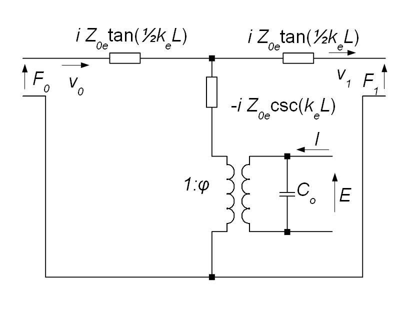
Those familiar with transmission line modeling of 33-mode and 31-mode piezoelectric pieces will notice that Martin’s model for the ring stack in Figure 13 has the form usually ascribed to the 31-mode piece. One usually sees the negative compliance in 33-mode pieces, and the lack of the negative compliance is often taken as an implication that the 31-mode is being used. Martin’s definition is unusual in that the negative compliance has been combined into the mechanical domain, whose material properties now depend on the electromechanical coupling coefficient through the definitions in Equations 8 through 10. This simplification by Martin is correct, although most other references have followed the lead of Redwood and kept the negative compliance as a separate analog circuit component.
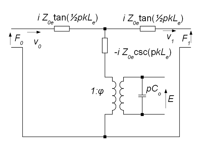
In the final part of his derivation, Martin connects copies of the analog circuit of Figure 13 with their mechanical ports cascaded end-to-end, and the electrical ports connected in parallel. Martin’s derived result for the ring stack is
| (12) |
From the similarity of Equations 11 and 12, Martin has shown that the analog circuit for the ring stack is that shown in Figure 14. Martin claims that the only assumption in this derivation for the ring stack is that the rings are identical and that the length of each ring is small compared to the wavelength. The complete analysis below will show that a broader set of restrictions is necessary for stacks with a large number of rings and for stacks made from material with high coupling coefficient.
Starting with Equation 11 with , one may successively add a single additional ring times. At each stage of this process, when the ring is added, the additional fractional error terms and are added as
| (13) |
where
| (14) | |||||
| (15) | |||||
Note that for and , all of these error terms are positive, and that they are monotonically increasing with increasing . To make this approximation, it is necessary to stipulate that the total length of the ring stack is short compared to the wavelength in the stack. It is not sufficient that a single ring be short. Note also the fact that the electromechanical coupling coefficient has a large impact on the error magnitude through the term approximately proportional to . When PZT or other conventional piezoelectric material is used, and if the effects of glue joints in the stack are considered, the effective coupling coefficient is generally less than 0.6. This was the case when the Martin papers were written. However, recent single crystal piezoelectric materials may have coupling coefficients over 0.9, and completed transducers using these materials can approach 0.85. This difference in coupling coefficient can increase the magnitude of the error by approximately an order of magnitude.
With modern computer hardware and software capabilities, there is little need to use the Martin approximation for current designs. However, designers should be aware of the limitations of Martin’s approximation to avoid its use in older analysis codes and to avoid introducing it into new analyses. Designers using high coupling piezoelectric materials must also guard against the previously safe intuitive understanding that stack segmentation has no effect on the mechanical behavior of a transducer employing a segmented stack. To the contrary, changes to the usual conventions of stack segmentation may provide interesting and useful modifications to the performance of transducers using high coupling piezoelectric materials.
References
- [1] Harry B. Miller, “Origin of the 33-driven ceramic ring-stack transducer,” J. Acoust. Soc. Am. 86(4) 1602-3, Oct. 1989.
- [2] W. P. Mason, “An electromechanical representation of a piezoelectric crystal used as a transducer,” Proc. I.R.E. 23, 1252-63, 1935; summary in Bell Sys. Tech. J. 14, 718-23, 1935.
- [3] Warren P. Mason, Electromechanical Transducers and Wave Filters, 2nd Ed., Van Norstrand, New York, 1948, pp. 399-404.
- [4] M. Redwood, “Transient performance of a piezoelectric transducer,” J. Acoust. Soc. Am. 33(4) 527-36, Apr. 1961.
- [5] Gordon E. Martin, “Vibrations of longitudinally polarized ferroelectric cylindrical tubes,” J. Acoust. Soc. Am. 35(4) 510-20, Apr. 1964.
- [6] Gordon E. Martin, “On the theory of segmented electromechanical systems,” J. Acoust. Soc. Am. 36(7) 1366-70, July 1964.
- [7] Gordon E. Martin, “Vibrations of coaxially segmented, longitudinally polarized ferroelectric tubes,” J. Acoust. Soc. Am. 36(8) 1496-1506, Aug. 1964.
- [8] Oscar Bryan Wilson, Introduction to Theory and Design of Sonar Transducers, Penninsula Publishing, Los Altos, CA, 1988, 118-9.
- [9] D. Stansfield, Underwater Acoustic Projectors, Penninsula Publishing, Los Altos, CA, 1991, see esp. pp. 184-5.
- [10] Nevin P. Sherlock and Richard J. Meyer, “Modified single crystals for high-power underwater projectors,” IEEE Trans. UFFC 59(4) 1285-91, June 2012.
- [11] David J. van Tol and Richard J. Meyer, “Acoustic transducer,” U.S. Patent No. 7,615,912 B2, Nov. 10, 2009.
- [12] Information on SPICE can be found at http://bwrc.eecs.berkeley.edu/Classes/IcBook/SPICE/ (date last viewed June 26, 2012).
- [13] L. W. Nagel, “SPICE2: A computer program to simulate semiconductor circuits,” Memo. No. UCB/ERL M520, U. Cal., Berkekey, May 9, 1975.
- [14] W. Marshall Leach, Computer-aided electroacoustic design with SPICE,” J. Audio Eng. Soc. 39(7/8) 1991, p. 551-562.
- [15] W. Marshall Leach, “Controlled-source analogous circuits and SPICE models for piezoelectric transducers,” IEEE Trans. Ultrason. Ferroelec. Freq. Cont. 41(1) 1994, p. 60-66.
- [16] The LTspice program is freely available from Linear Technology Corp. through their web site at http://www.linear.com (date last viewed June 26, 2012).
- [17] Other SPICE codes known to be suitable for this analysis are the open source gEDA suite available at http://www.geda.seul.org (date last viewed June 26, 2012), and PSPICE, which is currently available as part of the OrCAD suite from Cadance Design Systems, Inc. 2655 Seely Ave., San Jose, CA 95134.
- [18] Charles H. Sherman and John L. Butler, Transducers and Arrays for Underwater Sound, Appendix A.5, Springer, New York, 2007.
Figure Captions
-
1.
The tonpilz transducer element used in this study has a stack of eight PMN-PT crystal rings. (color online)
-
2.
Analog circuit model for a single piezoelectric piece, after Redwood. The mechanical domain includes the mechanical transmission line with density , sound speed , cross sectional area and length .
-
3.
The plane wave model of the transducer is an interconnection of mechanical transmission lines. The electrodes of the piezoelectric pieces are connected electrically in parallel.
-
4.
The piezoelectric stack is driven in four configurations, as eight segments, four segments, two segments and one segment. Electrodes remain in place for the eight rings, but not all are connected, as shown.
-
5.
The electrical admittance for transducers built with PZT-4 piezoelectric material do not vary significantly in the frequency region of the primary resonance and antiresonance .
-
6.
Electrical admittance of the four segmented stacks using PMN-PT show greater differences than with PZT in the frequency region of the primary antiresonance, and especially at the higher mode resonance.
-
7.
TVRs for the four transducer implementations using PZT-4.
-
8.
The TVR for transducers built with PMN-PT single crystal piezoelectric material show that segmentation may cause significant variation in operating bandwidth.
-
9.
In water electrical impedance magnitude for a single crystal PMN-PT based tonpilz element that was both measured and modeled in a) parallel and b) series stack arrangement.
-
10.
The measured Transmitting Voltage Response in water for a single tonpilz element of single crystal PMN-PT. The element was measured and modeled in a) series and b) parallel stack arrangement.
-
11.
Stack dimensions as used in the Martin reference[7].
-
12.
Analog circuit model for a single piezoelectric ring.
-
13.
A simplified approximate analog circuit when .
-
14.
Martin’s approximation for the piezoelectric ring stack.