Conformation-dependent electron transport through a biphenyl molecule: Circular current and related issues
Abstract
We investigate the conformation-dependent electron transfer in a biphenyl molecule within a simple tight-binding framework. The overall junction current and circular currents in two benzene rings driven by applied bias voltage are calculated by using Green’s function formalism. Our analysis may provide the possibilities of using organic molecules with loop substructures to design molecular spintronic devices, indicating the emergence of molecular spintronics.
pacs:
73.23.-b, 85.65.+h, 85.35.DsI Introduction
The study of electron transport through a molecular system attached to metallic electrodes is regarded as one of the most promising research fields in nanoscale technology and physics nitzan1 . With the discovery of advanced molecular scale measurement methodologies like scanning electro-chemical microscopy (SESM), scanning tunneling microscopy (STM), atomic force microscopy (AFM), etc., it is now possible to measure current flow through single molecules or cluster of molecules sandwiched between two electrodes chen . The proposed idea of designing molecule-based diode by Aviram and Ratner aviram in 1974 first illustrates the possibility of using molecules as active components of a device. Since then several ab-initio as well as model calculations have been done to investigate molecular transport theoretically ventra1 ; ventra2 ; sumit ; tagami ; orella1 ; orella2 ; arai ; walc ; san1 ; san2 ; san3 ; san4 . But experimental realizations took a little longer time to get feasible. In a pioneering experiment, Reed et al. investigated current-voltage (-) characteristics in a single benzene molecule coupled to metallic electrodes via thiol groups reed2 . Various other experiments using molecules have also been reported in literature exploring many interesting features e.g., ballistic transport, quantized conductance, negative differential resistance (NDR), gate controlled transistor operation, memory effects, bistable switching, conformational switching to name a few. Although a lot of theoretical mag ; lau ; baer1 ; baer2 ; baer3 ; gold and experimental reed1 ; tali ; fish ; cui ; gim studies have been made so far using different molecules, yet several problems are to be solved for further development of molecular electronics.
Most of the works associated with electronic conduction through molecular bridge systems are mainly concerned on the overall conduction properties. But a very few works are available where attention has been paid to the current distribution within the molecule itself having single or multiple loop substructures dist1 ; dist2 ; dist3 . Recently some interesting works have been done by Nitzan et al. and few other groups where possible quantum interference effects have been explored on current distribution through such molecular geometries due to the existence of multiple pathways, yielding the possibilities of voltage driven circular currents cir1 ; cir2 ; cir3 ; cir4 ; cir5 ; cir6 . The appearance of circular currents in loop geometries have already been reported in other contexts several years ago. This is commonly known as persistent currents in mesoscopic conducting rings where the current is induced by means of Aharonov-Bohm flux threaded by the ring butt2 ; levy ; gefen ; skm1 ; skm2 ; skm3 ; skm4 ; skm5 ; skm6 . The reason behind this current in isolated loop geometries is quite different from the previous one where current is driven by an applied bias voltage. It has been verified that the circular currents appear in molecular rings, driven by applied bias voltage, produce considerable magnetic fields at the centers of these rings. This phenomenon is somewhat interesting and can be used in different aspects in the study of molecular transport. For example, in presence of a local spin at the ring center one can regulate spin dependent transport through the molecular wire by tuning the orientation of that local spin, and, also the behavior of spin inelastic currents can be explained. In a recent work Galperin et al. rai have proposed some results towards this direction. One can also utilize this circular current generated magnetic field in other way to control spin dependent transport through a molecular wire without changing the orientation of the local spin. In that case we can change the strength of the magnetic field by some mechanisms. To test it, biphenyl molecule may the best example where two benzene rings are connected by a single C-C bond. It has been examined latha that in the case of a biphenyl molecule, electronic conductance changes significantly with the relative twist angle among two benzene rings. For the planar conformation conductance becomes maximum, while it gets decreased with increasing the twist angle. This phenomenon motivates us to describe conformation-dependent circular currents in a biphenyl molecule coupled to two metallic electrodes. We use a simple tight-binding (TB) framework to describe the model quantum system and evaluate all the results through Green’s function formalism. We believe that our present analysis will certainly provide some important information that can be used to design molecular spintronic devices in near future.
The structure of the paper is as follows. In section II, we describe the molecular model and theoretical formulation for the calculations. The essential results are presented in Section III which contains (a) transmission probability as a function of injecting electron energy and junction current through the molecular wire as a function of applied bias voltage for different twist angles, and (b) conformation-dependent circular currents in two benzene rings and associated magnetic fields at the ring centers. Finally, in section IV, we summarize our main results and discuss their possible implications for further study.
II Molecular Model and Theoretical Formulation
II.1 Tight-binding model
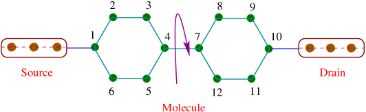
Figure 1 gives a schematic illustration of the molecular wire, where a biphenyl molecule is coupled to two semi-infinite one-dimensional (D) metallic electrodes, commonly known as source and drain. Our analysis for the present work is based on non-interacting electron picture, and, within this framework, TB model is extremely suitable for analyzing electron transport through a molecular bridge system.
The single particle Hamiltonian which captures the molecule and side-attached electrodes gets the form:
| (1) |
The first term corresponds to the Hamiltonian of the biphenyl molecule sandwiched between two electrodes. Under nearest-neighbor hopping approximation, the TB Hamiltonian of the molecule composed of () atomic sites reads,
| (2) | |||||
where the indices and are used for the left and right molecular rings, respectively. denotes the on-site energy of an electron at -(-)th site and describes the isotropic nearest-neighbor coupling between the molecular sites. () and () are the creation and annihilation operators, respectively, of an electron at the -(-)th site. The last term in the right hand side of Eq. 2 describes the coupling between two molecular rings. In terms of the relative twist angle among these two rings, the coupling strength gets the form: .
The second and third terms of Eq. 1 describe the Hamiltonians for the D semi-infinite electrodes (source and drain) and molecule-to-electrode coupling. In Wannier basis representation they are expressed as follows.
and,
| (4) | |||||
Here, and correspond to the site energy and nearest-neighbor hopping integral in the electrodes. and are the creation and annihilation operators, respectively, of an electron at the site of the electrodes. The coupling strength between the source and the molecule is , while it is between the molecule and the drain. The source and drain are coupled to the molecule through -th and -th atomic sites, respectively, those are variable.
II.2 Two-terminal transmission probability and junction current
To obtain transmission probability of an electron from source to drain electrode through the molecule, we use Green’s function formalism. Within the regime of coherent transport and in the absence of Coulomb interaction this technique is well applied.
The single particle Green’s function operator representing the entire system for an electron with energy is defined as,
| (5) |
where, . Following the matrix forms of and , the problem of finding in the full Hilbert space of can be mapped exactly to a Green’s function corresponding to an effective Hamiltonian in the reduced Hilbert space of the molecule itself and we have datta ,
| (6) |
Here, and are the contact self-energies introduced to incorporate the effect of coupling of the molecule to the source and drain, respectively. In terms of this effective Green’s function , two-terminal transmission probability through the molecular wire can be written as datta ,
| (7) |
where, and are the coupling matrices, and, and are the retarded and advanced Green’s functions, respectively.
With the knowledge of the transmission probability we compute overall junction current () as a function of bias voltage () using the standard formalism based on quantum scattering theory.
| (8) |
Here, and are the Fermi functions of the source and drain, respectively. At absolute zero temperature the above equation boils down to the following expression.
| (9) |
where, is the equilibrium Fermi energy.
II.3 Circular current and associated magnetic field
In order to calculate circular current in molecular rings of the biphenyl molecule let us first concentrate on the current distribution in a simple loop geometry illustrated in Fig. 2. A net current
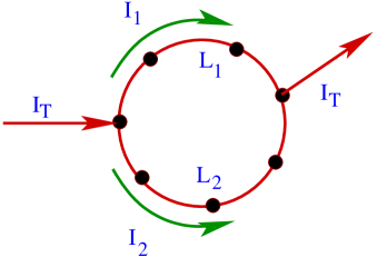
flows between two electrodes through a quantum ring, where and are the currents flowing through upper and lower arms of the ring, respectively. We assign positive sign to the current propagating in the counter-clockwise direction. With this current distribution, we define circular current of the ring as cir1 ,
| (10) |
where, and are the lengths of the upper and lower arms of the ring, respectively, and . Thus, in order to compute , following the above relation, we need to know the currents in different branches of the loop geometry. We evaluate these currents by using Green’s function formalism. At absolute zero temperature the current flowing from site to () is given by the expression.
| (11) |
where, is the current density. In terms of the correlation function it can be written as dist3 ,
| (12) |
where, . This correlation function is evaluated by setting the occupation function of the source to unity and that of the drain to zero.
Finally, we determine the local magnetic field at any point inside the ring, associated with circular current , from the Biot-Savart’s Law cir1 ,
| (13) |
where, is the magnetic constant and is the position vector of an infinitesimal bond current element . Using the above expressions we evaluate circular currents and associated magnetic fields in two molecular rings of the biphenyl molecule.
Throughout this work, we assume that the entire voltage is dropped across the molecule-to-electrode interfaces and this assumption is good enough for molecules of smaller size. We also restrict ourselves at absolute zero temperature and choose the units where .
III Numerical Results and Discussion
In this section we present numerical results computed for transmission probability, overall junction current and circular currents in a biphenyl molecule under conventional biased conditions. Throughout our analysis we set the on-site energies in the molecule as well as in the source and drain electrodes to zero, . The nearest-neighbor coupling strength in the electrodes () is fixed at eV, while in the molecule () it is set at eV. The coupling strengths of the molecule to the source and drain electrodes, characterized by the parameters and , are also set at eV. We fix the equilibrium Fermi energy at zero and measure the energy scale in unit of .
III.1 Transmission probability and junction current
In Fig. 3 we show the variation of transmission probability as a function of injecting electron energy when the source and drain are coupled to the biphenyl molecule at the sites () and (), respectively. The red curve corresponds to , while the green and blue lines are associated with and , respectively.
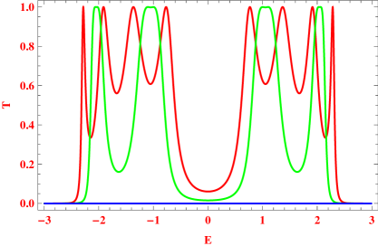
From the spectrum it is observed that the transmission probability exhibits resonant peaks (red and green lines) for some particular energies and at these resonances it () almost reaches to unity. All these resonant peaks are associated with the energy eigenvalues of the molecule, and therefore, we can say that the transmittance spectrum is a fingerprint of the electronic structure of the molecule. The number of
resonant peaks in - spectrum and their corresponding widths for a particular molecule-to-electrode configuration notably depend on the molecular twist angle, which is clearly visible from the red and green curves. Depending on the twist angle , the resonating energy states are available at different energies. For each of these energy eigenstates a resonant peak appears in the transmission spectrum with a finite width associated with the molecular coupling strength. Now if the resonating states with different energies are very closely placed then the neighboring peaks can overlap with each other which result a broader peak. For low enough molecular coupling, the overlap between neighboring resonant peaks is no longer possible, and therefore, separate peaks with identical broadening will be obtained in the transmission spectrum. Obviously, for different states having identical energy i.e., for degenerate states a single resonant peak is generated in the transmission curve. The situation especially changes when i.e., one molecular ring becomes perpendicular with
respect to the other ring. In this particular case the transmission probability completely disappears for the entire energy band spectrum. It is shown by the blue curve in Fig. 3. With the increment
of the twist angle between these two molecular rings, the degree of -conjugation between them decreases, which results the reduction of the junction conductance since the electronic transfer rate through the molecule scales as the square of the -overlap nitz . For , the -conjugation between the molecular rings completely disappears, and accordingly, vanishing transmission probability is obtained. Thus, rotating one benzene molecule relative to the other one can regulate electronic transmission through the biphenyl molecule and eventually one can get the insulating phase, which leads to the possibility of getting a switching action using this molecule.
The sharpness of the resonant peaks in - spectrum strongly depends on the molecular coupling strength to side-attached electrodes, and, it greatly controls electron transfer through the bridge system. In the limit of weak-coupling i.e., , sharp resonant peaks are observed in transmission spectrum, whereas widths of these peaks get broadened in the limit of strong-coupling, .
The broadening of transmission peaks with the enhancement in coupling strength is quantified by the imaginary parts of the self-energy matrices and which are incorporated in the transmittance expression via the coupling matrices and . This coupling effect on electron transport has already been explored elaborately in literature sm1 ; sm2 ; sm3 ; sm4 , and therefore, in the present work we do not illustrate it further.
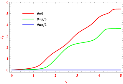
The fundamental features of electron transport will be more transparent from our current-voltage characteristics. The overall junction current
through the molecular wire following Landauer-Büttiker formalism (Eq. 9). In Fig. 4 we display the variation of junction current as a function of applied bias voltage for the biphenyl molecule where the electrodes are connected at the molecular sites and , same as in Fig. 1. The current varies quite continuously with the voltage bias. Depending on the molecular coupling to the source and drain electrodes, the current exhibits continuous-like or step-like behavior since it is computed by integrating over the transmission curve. For the weak molecular coupling step-like nature associated with sharp resonant peaks in transmission spectrum will be obtained, unlike to the continuous-like feature as observed in the limit of strong-coupling. Therefore, for a fixed voltage bias one can regulate the current amplitude by tuning molecular coupling strength, and, this phenomenon provides an interesting behavior in designing molecular electronic devices. Figure 4 reveals that the junction current decreases with increasing the relative twist angle, following the - characteristics. In addition to this behavior, it is also important to note that the threshold bias voltage of electron conduction firmly depends on the twist angle , which is clearly noticed by comparing the red and green curves in Fig. 4.
In order to explore the dependence of electron conduction through the biphenyl molecule for any arbitrary angle of twist, in
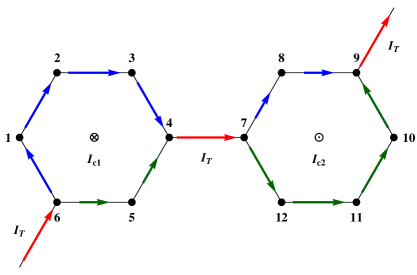
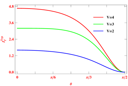
Fig. 5 we present the variation of junction current as a function of relative twist angle for some typical bias voltages. The spectrum shows that for the planar conformation total current amplitude becomes maximum and it gradually decreases with the relative twist angle and eventually drops to zero when . Thus, at no electron conduction will take place through this molecular bridge system, while for other choices of electron can transfer through the molecule from the source to drain electrode, which promotes a conformation-dependent switching action using the biphenyl molecule.
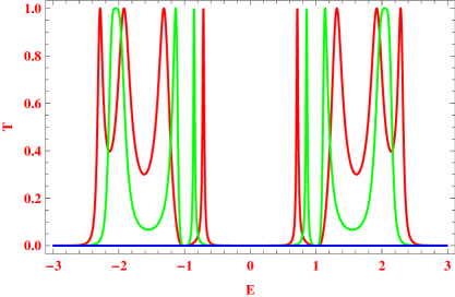
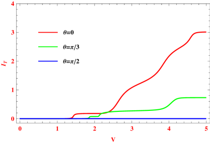
A significant change in the transmission spectrum is realized when the electrodes are coupled to the molecule in such a way that the upper and lower arms of each molecular rings have unequal lengths. In Fig. 6 we present the results for such a particular configuration where the source and drain are attached to the molecular sites and , respectively. The red, green and blue curves correspond to the results for the identical parameter values chosen in Fig. 3. From the transmission curves (red and green) we make out that for a wide energy range across , electron conduction does not take place, and also the widths of some resonant peaks get reduced enormously compared to the symmetric configuration where upper and lower arms in each of the two molecular rings are identical (Fig. 3), even though the molecule-to-electrode coupling strength is kept unchanged. This is solely due to the effect of quantum interference among the electronic waves passing through different arms of the molecular rings, and, it can be much clearly analyzed through the following arguments. For a fixed molecular coupling, the broadening of different resonant peaks which results from the overlap of neighboring peaks depends on the location of energy levels, as discussed earlier. The positions of these energy levels, on the other hand, are directly associated with the molecule itself and the real parts of the self-energy matrices and which correspond to the shift of the energy eigenstates of the sample sandwiched between two electrodes. Thus for a particular molecule-to-electrode configuration we get one set of resonating energy levels, while for the other configuration a different set of energy levels is obtained. These generate transmission peaks with different widths associated with the level spacing. If the molecular coupling strength is low enough, then a minor shift of molecular energy levels takes place, and therefore, almost identical - spectrum will be observed for different molecule-to-electrode configurations. But, for moderate coupling strength one can regulate electron conduction through the bridge system in a tunable way by introducing more asymmetry among these two arms. This behavior is nicely reflected in the current-voltage characteristics. The results are bestowed in Fig. 7. It is clearly observed that for a particular bias voltage the current amplitude decreases significantly compared to the symmetric configuration, Fig. 4. The symmetry breaking among the molecular arms also tunes the threshold voltage of electron conduction across the molecular wire for a particular twist angle , as found by comparing Figs. 4 and 7.
III.2 Circular current and magnetic field
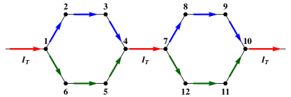
Now we focus our attention on the behavior of circular currents and associated magnetic fields at the ring centers of the molecule. These factors are highly sensitive to the molecule itself as well as the molecule-to-electrode interface geometry. To address these issues, we start with the current distribution within the molecule when it is coupled to the electrodes in such a way that the upper and lower arms of the molecular rings have identical lengths. The current distribution is shown in Fig. 8, where the blue and green arrows indicate the bond currents in upper and lower arms of the rings, respectively. The arrow sizes represent the magnitudes of bond currents and they are computed when the bias voltage is fixed at V. Here is the net junction current, shown by the red arrow, which is distributed among different branches at the junction point. Due to the geometrical symmetry reasons, the magnitudes of the bond currents in upper and lower arms of the two rings are exactly identical and since they are propagating in opposite directions, no net circulating current will appear which results vanishing magnetic fields at the ring centers.
In order to establish circular currents in these two molecular rings, we
attach the electrodes asymmetrically such that the upper and lower arms of the rings have unequal lengths. The internal current distribution for such a particular configuration is illustrated in Fig. 9, where we set the same bias voltage as taken in Fig. 8. In this situation the bond currents get unequal magnitudes, and accordingly, circular
currents are established in the two molecular rings. The magnetic fields at the ring centers associated to these circular currents are also shown. In the left ring, the magnetic field is directed along the downward direction, represented by encircled cross, while in the other ring it is directed along the upward direction, illustrated by encircled dot. We calculate the magnetic fields using Biot-Savart’s Law, Eq. 13, and scale them in unit of , where is the perpendicular distance from the center to any arm of the molecular ring and the factor appears due to the existence of six bonds in each benzene ring.
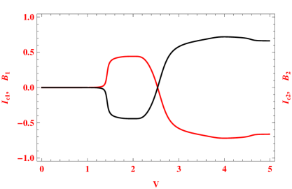
Figure 10 demonstrates the magnitudes of the circular currents and the associated magnetic fields at the ring centers as a function of voltage bias for the planar conformation of the biphenyl molecule. From the spectrum we notice that in one voltage regime (V) no circulating current appears, while other voltage regimes finite circular currents are available and the sign of these currents also changes depending on the voltage region. The associated magnetic fields also follow the same behavior, as illustrated in the spectrum. This phenomenon can be explained as follows. The circular current in a loop geometry is associated with energy eigenstates those can be described by current carrying states with the current flowing in opposite directions. Now, for a finite bias voltage whenever one of these resonant states lies in the Fermi window, associated with the applied voltage bias and the nature of voltage drops along the molecular wire, we will get the corresponding circular current. When more than one resonant states come within this Fermi window, all of them contribute to the current which provide a net signal, and, in the particular case when they mutually cancel each other, the net signal becomes zero. The sign of this net circular current or direction of associated magnetic field depends on which resonant states dominate the others, which again certainly depends on the applied bias voltage. From the above analysis we can clearly understand the vanishing nature of circulating current in the above mentioned voltage region (V), since up to this voltage window no resonant state appears which can contribute to the circulating current. This, on the other hand, is also justified from the red curve in - spectrum, Fig. 6, which is drawn for the planar conformation of the molecule. It indicates that within the energy window to i.e., when the bias voltage becomes V, no electron transmission takes place through the molecule, which results zero circulating current. For the other voltage regimes finite circular currents are available depending on the voltage region.
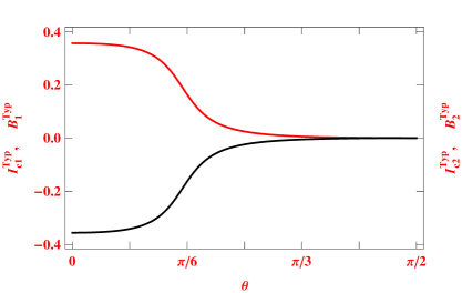
Finally, we focus on the variation of circular currents and corresponding magnetic fields at the ring centers as a function of relative twist angle , when the voltage bias is kept constant. The results are shown in Fig. 11, where two different colored curves represent the similar meaning as in Fig. 10. Quite interestingly we see that the magnitudes of the magnetic fields at the centers of two molecular rings decreases monotonically with relative twist angle , and for large enough they eventually reduce to zero. Thus, for a particular bias voltage one can tune the strength of magnetic field established at the ring center due to this circular current simply by twisting one benzene molecule relative to the other, and hence, by placing a local spin or a magnetic ion at the ring center, which will interact to the magnetic field, spin selective transmission can be achieved through this molecular system. This conformation-dependent spin selective transmission will be investigated in a recent forthcoming paper.
IV Conclusion
In conclusion, we have investigated in detail the conformation-dependent two-terminal electron transport through a biphenyl molecule within a simple tight-binding framework using Green’s function formalism. Two principal results have been obtained and analyzed. First, the dependence of molecular twist on electronic transmission probability and the overall junction current have been discussed. Our results lead to a possibility of getting the conformation-dependent switching action using this molecule. Second, we have investigated the variation of circular currents and associated magnetic fields developed at the ring centers as a function of the relative twist angle. Tuning this angle, one can tailor the strength of magnetic field at the ring centers, and, we believe that the present analysis may provide the possibilities to design molecular spintronic devices using organic molecules with loop substructures.
Throughout our work we have ignored the inter- and intra-site Coulomb interactions as well as the effect of the electrodes, which we plan to consider in our future works. Another important assumption is the zero temperature approximation. Though all the results presented in this communication are worked out at absolute zero temperature limit, the results should remain valid even at finite temperatures (K) since the broadening of the energy levels of the biphenyl molecule due to its coupling with the metal electrodes is much higher than that of the thermal broadening datta .
V Acknowledgment
The author is thankful to Prof. Abraham Nitzan for many stimulating discussions.
References
- (1) A. Nitzan and M. A. Ratner, Science 300, 1384 (2003).
- (2) F. Chen and N. J. Tao, Acc. Chem. Res. 42, 429 (2009).
- (3) A. Aviram and M. Ratner, Chem. Phys. Lett. 29, 277 (1974).
- (4) M. D. Ventra, S. T. Pentelides, and N. D. Lang, Appl. Phys. Lett. 76, 3448 (2000).
- (5) M. D. Ventra, N. D. Lang, and S. T. Pentelides, Chem. Phys. 281, 189 (2002).
- (6) D. M. Cardamone, C. A. Stafford, and S. Mazumdar, Nano Lett. 6, 2422 (2006).
- (7) K. Tagami, L. Wang, and M. Tsukada, Nano Lett. 4, 209 (2004).
- (8) P. Orellana and F. Claro, Phys. Rev. Lett. 90, 178302 (2003).
- (9) J. H. Ojeda, R. P. A. Lima, F. Domínguez-Adame, and P. A. Orellana, J. Phys.: Condens. Matter 21, 285105 (2009).
- (10) M. Araidai and M. Tsukada, Phys. Rev. B 81, 235114 (2010).
- (11) K. Walczak, Cent. Eur. J. Chem. 2, 524 (2004).
- (12) P. Dutta, S. K. Maiti, and S. N. Karmakar, Org. Electron. 11, 1120 (2010).
- (13) M. Dey, S. K. Maiti, and S. N. Karmakar, Org. Electron. 12, 1017 (2011).
- (14) S. K. Maiti, Physica B 394, 33 (2007).
- (15) S. K. Maiti, Solid State Commun. 150, 1269 (2010).
- (16) M. A. Reed, C. Zhou, C. J. Muller, T. P. Burgin, and J. M. Tour, Science 278, 252 (1997).
- (17) M. Magoga and C. Joachim, Phys. Rev. B 59, 16011 (1999).
- (18) J.-P. Launay and C. D. Coudret, in: A. Aviram and M. A. Ratner (Eds.), Molecular Electronics, New York Academy of Sciences, New York, (1998).
- (19) R. Baer and D. Neuhauser, Chem. Phys. 281, 353 (2002).
- (20) R. Baer and D. Neuhauser, J. Am. Chem. Soc. 124, 4200 (2002).
- (21) D. Walter, D. Neuhauser, and R. Baer, Chem. Phys. 299, 139 (2004).
- (22) R. H. Goldsmith, M. R. Wasielewski, and M. A. Ratner, J. Phys. Chem. B 110, 20258 (2006).
- (23) J. Chen, M. A. Reed, A. M. Rawlett, and J. M. Tour, Science 286, 1550 (1999).
- (24) T. Dadosh, Y. Gordin, R. Krahne, I. Khivrich, D. Mahalu, V. Frydman, J. Sperling, A. Yacoby, and I. Bar-Joseph, Nature 436, 677 (2005).
- (25) C. M. Fischer, M. Burghard, S. Roth, and K. V. Klitzing, Appl. Phys. Lett. 66, 3331 (1995).
- (26) X. D. Cui, A. Primak, X. Zarate, J. Tomfohr, O. F. Sankey, A. L. Moore, T. A. Moore, D. Gust, G. Harris, S. M. Lindsay, Science 294, 571 (2001).
- (27) J. K. Gimzewski and C. Joachim, Science 283, 1683 (1999).
- (28) M. Tsukada, K. Tagami, K. Hirose, and N. Kobayashi, J. Phys. Soc. Jpn. 74, 1079 (2005).
- (29) S. Nakanishi and M. Tsukada, Surf. Sci. 438, 305 (1999).
- (30) L. Wang, K. Tagami, and M. Tsukada, Jpn. J. Appl. Phys. 43, 2779 (2004).
- (31) D. Rai, O. Hod, and A. Nitzan, J. Phys. Chem. C 114, 20583 (2010).
- (32) D. Rai, O. Hod, and A. Nitzan, J. Phys. Chem. Lett. 2, 2118 (2011).
- (33) D. Rai, O. Hod, and A. Nitzan, Phys. Rev. B 85, 155440 (2012).
- (34) G. Stefanucci, E. Perfetto, S. Bellucci, and M. Cini, Phys. Rev. B 79, 073406 (2009).
- (35) K. Tagami and M. Tsukada, Curr. Appl. Phys. 3, 439 (2003).
- (36) P. Sautet and C. Joachim, Chem. Phys. Lett. 153, 511 (1988).
- (37) M. Büttiker, Y. Imry, and R. Landauer, Phys. Lett. A 96, 365 (1983).
- (38) L. P. Levy, G. Dolan, J. Dunsmuir, and H. Bouchiat, Phys. Rev. Lett. 64, 2074 (1990).
- (39) H. F. Cheung, Y. Gefen, E. K. Reidel, and W. H. Shih, Phys. Rev. B 37, 6050 (1988).
- (40) S. K. Maiti, J. Chowdhury, and S. N. Karmakar, Phys. Lett. A 332, 497 (2004).
- (41) S. K. Maiti, J. Chowdhury, and S. N. Karmakar, Solid State Commun. 135, 278 (2005).
- (42) S. K. Maiti, M. Dey, S. Sil, A. Chakrabarti, and S. N. Karmakar, Europhys. Lett. 95, 57008 (2011).
- (43) S. K. Maiti, J. Appl. Phys. 110, 064306 (2011).
- (44) S. K. Maiti, Solid State Commun. 150, 2212 (2010).
- (45) S. K. Maiti, Physica E 31, 117 (2006).
- (46) D. Rai and M. Galperin, Phys. Rev. B 86, 045420 (2012).
- (47) L. Venkataraman, J. E. Klare, C. Nuckolls, M. S. Hybertsen, and M. L. Steigerwald, Nature 442, 904 (2006).
- (48) S. Datta, Electronic transport in mesoscopic systems, Cambridge University Press, Cambridge (1997).
- (49) A. Nitzan, Annu. Rev. Phys. Chem. 52, 681 (2001).
- (50) S. K. Maiti, Org. Electron. 8, 575 (2007).
- (51) S. K. Maiti, Phys. Scr. 75, 62 (2007).
- (52) S. K. Maiti, Solid State Commun. 149, 2146 (2009).
- (53) S. K. Maiti, Solid State Commun. 149, 973 (2009).