Proposal for Manipulation of Majorana Fermions in Nano-Patterned Semiconductor-Superconductor Heterostructure
Abstract
We investigate a heterostructure system with a spin-orbit coupled semiconductor sandwiched by an -wave superconductor and a ferromagnetic insulator, which supports Majorana fermions (MFs) at the superconducting vortex cores. We propose a scheme of transporting and braiding the MFs, which only requires application of point-like gate voltages in a system with nano-meter patterns. By solving the time-dependent Bogoliubov-de Gennes equation numerically, we monitor the time evolutions of MF wave-functions and show that the braiding of MFs with non-Abelian statistics can be achieved by adiabatic switching within several nano seconds.
Graduate School of Pure and Applied Sciences, University of Tsukuba, Tsukuba 305-8571, Japan \alsoaffiliationGraduate School of Pure and Applied Sciences, University of Tsukuba, Tsukuba 305-8571, Japan
Introduction. Majorana fermions (MFs) are particles equivalent to their own anti-particles 1. Great research effort has been devoted to searching for MFs in condensed matter systems in the last decade since the particles can be used for constructing topological quantum computers 2, 3, 4. Systems that attract most attentions include Pfaffian fractional quantum Hall state 5, chiral p-wave superconductors (SCs) 6, one-dimensional (1D) spinless SCs 7, superfluidity of cold atoms 8, 9, to name a few. Recently, two heterostructure systems are suggested as possible MF hosts, namely the topological insulator in proximity to -wave SC 10 and the spin-orbit coupled semiconductor (SM) sandwiched by s-wave SC and ferromagnetic insulator (FI) (SC/SM/FI) 11, 12, 13. At the same time, a 1D semiconductor nanowire with spin-orbit coupling in proximity to -wave SC was investigated both theoretically and experimentally for realizing MFs 14, 15, 16, 17, 18, 19, 20. Lately, a promising signal of MFs has been captured in the device of InSb nanowire/-wave SC 20. In these hybrid systems, the p-wave pairing are superseded by the interplay between proximity-induced -wave superconductivity and strong spin-orbit coupling.

It was revealed that MFs appear inside vortex cores in a chiral p-wave SC 6, and that non-Abelian statistics can be achieved by exchanging positions of vortices hosting MFs 21. However, it is difficult to manipulate vortices in experiments, which may hinder the realization of this genius idea. To circumvent this problem, MFs at sample edges of topological SC have been considered 22. Making use of the topological property, edge MFs can be braided with the desired non-Abelian statistics merely by tuning point-like gate voltages on links among topological SC samples. In order to make the edge MFs stable, one needs to embed the device into a good insulator. The size of topological SCs should also be chosen carefully since the wave-functions of edge MFs become too dilute for large samples, which makes edge MFs fragile due to excited states.
In this work we demonstrate that the core MFs can be liberated from vortices, transported and braided by applications of local gate voltages. This scheme takes full advantages of SC/SM/FI heterostructure in the way shown schematically in Figure 1: four holes are punched in the SM layer and one vortex is induced and pinned right beneath each hole in the common superconductor substrate; three electrodes are placed above the small regions between holes, and the ones at high voltage state (pink rectangular prisms in Figure 1) connect holes by killing electron hoppings in SM locally. The linear dimension of holes and separation between holes should be in the regime of tens of nano-meters 22: for too large holes, the energy gap between the zero-energy MFs and the lowest excited states becomes very small, which limits the operation temperature, while for too small holes especially at the part of keyhole tail MF wave-functions interact with each other, which destroys the MF ground state.
The key observation is that the geometric topology of the SM layer can be controlled by local gate voltages, and that when even number of holes are connected, core MFs fuse into quasi-particle states with finite energies, while one core MF exists when odd number of holes are connected, since the unified perimeter includes even and odd number of vortices in the two cases respectively. Core MFs can then be liberated from and transported among vortices with a sequence of turning on and off gate voltages at the electrodes. In order to keep the topological protection, one needs to switch gate voltages in an adiabatic way. To monitor the dynamics of MFs, we solve numerically the time-dependent Bogoliubov-de Gennes (TDBdG) equation with high precision. It is then found that, with reasonable materials parameters, adiabatic manipulations of MFs and thus non-Abelian statistics can be achieved within several nano seconds, which reveals that the present scheme has the application potential for topological qubits and topological quantum computation.
Topological superconductivity. We start from the tight-binding Hamiltonian of a SM with Rashba-type spin-orbit coupling on a square lattice in proximity to a ferromagnetic insulator 22
| (1) |
where and are the nearest-neighbor hopping rates of electrons with reserved and flipped spin directions; and are chemical potential and strength of Zeeman field respectively; creates one electron with spin at lattice site ; are the Pauli matrices.
The proximity-induced superconductivity in SM is described by
| (2) |
where is the pairing potential at site . The BdG equation is then given by
| (3) |
with the Nambu spinor notation , which defines the quasi-particle operator

To reveal the topological nature of the system, we evaluate the Chern number (also known as the TKNN index) 23. For this purpose, we treat first the system in -space on the basis . The Hamiltonian then reads
| (4) |
where , . Diagonalizing , we obtain the eigenstates and band structure in the first Brillouin zone , as shown in Figure 2(a). The band topology is characterized by the Chern number
| (5) |
with Berry connection for all occupied bands (). Integrating the Berry curvature shown in Figure 2(a) over the Brillouin zone 24, we find that when the Zeeman field satisfies with , which is attributed to the topologically nontrivial energy gap at while those at , and remain trivial 12, 14, 25. The nonzero Chern number indicates that the system is topological and thus may support MFs. The above result is consistent with the approximation treatment around point 25.
Core Majorana fermions. We study a finite sample with two separated holes in the SM and two vortices pinned right beneath them (see top panel of Figure 2(b)). The typical size of a square sample is 300nm300nm, which is divided into square grids, corresponding to Hamiltonian matrix of dimension in (3). By solving the BdG equation for this case, we obtain the energy spectra of excitations both at the vortex cores and the sample edge. Two zero-energy states are found at the holes, whereas no such state at the edge, as shown in Figure 2(c). We examine the four spinor components of the zero-energy states, and find and (displayed explicitly in Figure 2(d) only for the right hole), which results in , indicating that the two zero-energy states are Majorana states.
It should be noticed that the excitation energy gap at vortices is about four times larger than that at the edge (see 2(c)), which makes the core MFs more stable than edge MFs 22. On the other hand, because the minigap associated with Andreev bound states at superconducting vortex core proximity-induced in SM is roughly with a small Fermi energy 26, the influence from Andreev bound states to the core MFs can be neglected. It is in contrast to the case of SC exposed to vacuum where and thus the minigap is small in order of .
Next, we impose a point-like gate voltage on the region between the two holes to prohibit direct hopping of electrons by lifting the on-site energy there as in the bottom panel of Figure 2(b) (see also Figure 1), which merges effectively the two isolated holes into a unified one. Solving the BdG equation for this case, there is no zero-energy quasi-particle excitation state, since the combined hole includes two vortices 27.
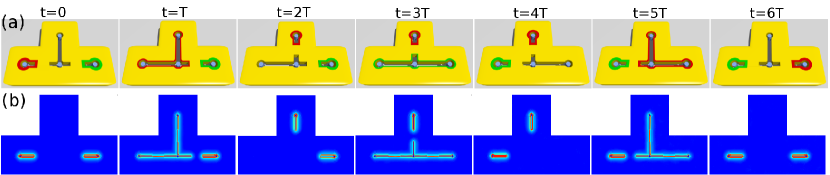
Based on the above result, we can design a way to liberate and transport a MF from one vortex to another (see the first three columns in Figure 3). Initially, the top and middle holes are connected together while the leftmost one is isolated and hosts a MF. We then combine these three holes by applying gate voltages on the region between the left and middle ones, which causes the MF to spread itself over the unified hole including three vortices (). Finally, the MF is moved totally to the top by disconnecting the top hole from others (). It is noticed that the collapsing of MF wave-function on the top hole is a topological property, and is impossible for electrons. Solving BdG equation numerically, we confirm that the gap between the zero-energy MF states and the excitations remains finite during the whole process, which guarantees the topological protection.
Being able to transport one MF from one hole to another, we proceed to exchange positions of two core MFs in the system shown in Figure 3 (see also Figure 1). Following the above transporting procedures, we further move the green MF from the right hole to the left one during . At last, the red MF stored temporarily at the top hole is transported to the right one in the period . After the sequence of switching processes, the system comes back to the original state with the red and green MFs exchanged.
In order to investigate the impact of the position exchange to the MF state, we monitor the time evolution of MF wave functions by solving the TDBdG equation numerically
| (6) |
where is given in Figure 3 and depends on time via the hopping rates and in the regions between holes, which are tuned adiabatically by the local gate voltages 22.
Even with the powerful computation resources available in these days, it is still hopeless to tackle this problem by directly diagonalizing the Hamiltonian of dimension for each time instant. Fortunately, it has been revealed that when the exponential operator is expanded by the Chebyshev polynomial
| (7) |
the coefficient decreases with exponentially fast for small 28. Therefore, only several leading terms are necessary for a sufficiently accurate estimate of . Moreover, the Chebyshev polynomials can be constructed based on the recursive relation , which reduces the computation time further. In this way, the time-dependent wave-function of the MFs can be obtained efficiently in an iterative way .
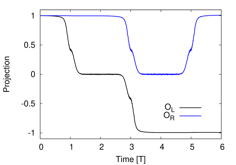
The wave function is the superposition of the zero-energy states and at left and right holes respectively as shown in Figure 3(a). We evaluate the projections of onto the initial states and and display them in Figure 4 for . The two MFs pick up opposite signs after exchanging their positions, which can be summarized by
| (8) |
Since (8) can be written as with the unitary matrix , the braiding of MFs satisfies non-Abelian statistics 18, 19, 22, 29.
The braiding rule (8) can also be understood by the three pairs of opposite motions of MFs across links between holes during the whole process displayed in Figure 3, since each pair of opposite motions contributes -1 and , which indicating that either or has to change sign 22.
The above scheme for the braiding of MFs shows good scalability. For a device in Figure 5 constructed by the unit displayed in Figure 1, one can exchange any two MFs by a sequence of switchings of point-like gate voltages. It is straightforward to figure out that any MF-pair exchanging accompanies odd number of opposite motions of MFs across links between holes, which guarantees the non-Abelian statistics 22. Therefore, the present scheme has the potential to be used for large scale manipulation of topological qubits.

Conclusion. We have shown that the Majorana fermions hosted by vortex cores in topological superconductors can be liberated from pinned vortices, transported and braided over the prepared holes, taking advantages of the heterostructure of s-wave superconductor and spin-orbital coupling semiconductor. By solving the time-dependent Bogoliubov-de Gennes equation numerically, we monitor the time evolutions of Majorana fermion wave-functions and demonstrate the non-Abelian statistics of adiabatical braidings of Majorana fermions. The present scheme only requires local applications of gate voltages, and minimizes possible disturbances to the Majorana fermions, which might be a challenging issue in other proposals based on end Majorana fermions in one-dimensional superconductors where gate voltages are necessary along the whole system. As compared with the edge Majorana fermions in two-dimensional topological superconductors, the core Majorana fermions are protected by a larger energy gap, and thus reduce the limitation on operating temperatures. Therefore, the present scheme provides a more feasible way for manipulating Majorana fermions in large scale.
X.H. thanks Y. Kato for useful discussions. This work was supported by WPI initiative on Materials Nanoarchitectonics, MEXT of Japan.
References
- 1 Majorana, E. Nuovo Cimento 1937, 5, 171.
- 2 Kitaev, A. Y. Ann. Phys. 2003, 303, 2.
- 3 Nayak, C.; Simon, S. H.; Stern, A.; Freedman, M.; Das Sarma, S. Rev. Mod. Phys. 2008, 80, 1083.
- 4 Wilczek, F. Nature Phys. 2009, 5, 614.
- 5 Moore, G.; Read, N. Nucl. Phys. B 1991, 360, 362.
- 6 Read, N.; Green, D. Phys. Rev. B 2000, 61, 10267.
- 7 Kitaev, A. Y. Phys. -Usp. 2001, 44, 131.
- 8 Tewari, S.; Das Sarma, S.; Nayak, C.; Zhang, C.-W.; Zoller, P. Phys. Rev. Lett. 2007, 98, 010506.
- 9 Sato, M.; Takahashi, Y.; Fujimoto, S. Phys. Rev. Lett. 2009, 103, 020401.
- 10 Fu, L.; Kane, C. L. Phys. Rev. Lett. 2008, 100, 096407.
- 11 Sau, J. D.; Lutchyn, R. M.; Tewari, S.; Das Sarma, S. Phys. Rev. Lett. 2010, 104, 040502.
- 12 Alicea, J. Phys. Rev. B 2010, 81, 125318.
- 13 Linder, J.; Tanaka, Y.; Yokoyama, T.; Sudbø, A.; Nagaosa, N. Phys. Rev. Lett. 2010, 104, 067001.
- 14 Lutchyn, R. M.; Sau, J. D.; Das Sarma, S. Phys. Rev. Lett. 2010, 105, 077001.
- 15 Oreg, Y.; Rafael, G.; Oppen, F. von Phys. Rev. Lett. 2010, 105, 177002.
- 16 Hassler, F.; Akhmerov, A. R.; Hou, C.-Y.; Beenakker, C. W. J. New J. Phys. 2010, 12, 125002.
- 17 Potter, A. C.; Lee, P. A. Phys. Rev. Lett. 2010, 105, 227003.
- 18 Sau, J. D.; Clarke, D. J.; Tewari, S. Phys. Rev. B 2011, 84, 094505.
- 19 Heck, B. van; Akhmerov, A. R.; Hassler, F.; Burrello, M.; Beenakker, C. W. J. New J. Phys. 2012, 14, 035019.
- 20 Mourik, V.; Zuo, K.; Frolov, S. M.; Plissard, S. R.; Bakkers, E. P. A. M.; Kouwenhoven, L. P. Science 2012, 336, 1003.
- 21 Ivanov, D. A. Phys. Rev. Lett. 2001, 86, 268.
- 22 Liang, Q.-F.; Wang Z.; Hu, X. Europhys. Lett. 2012, 99, 50004.
- 23 Thouless, D. J.; Kohmoto, M.; Nightingale, M. P.; Nijs, M. den Phys. Rev. Lett. 1982, 49, 405.
- 24 Fukui, T.; Hatsugai, Y.; Suzuki, H. J. Phys. Soc. Jpn. 2005, 74, 1674.
- 25 Sato, M.; Takahashi, Y.; Fujimoto, S. Phys. Rev. B 2010, 82, 134521.
- 26 Sau, J. D.; Lutchyn, R. M.; Tewari, S.; Sarma, S. Das Phys. Rev. B 2010, 82, 094522.
- 27 Tewari, S.; Das Sarma, S.; Lee, D.-H. Phys. Rev. Lett. 2007, 99, 037001.
- 28 Loh, Y. L.; Taraskin, S. N.; Elliott, S. R. Phys. Rev. Lett. 2000, 84, 2290.
- 29 Alicea, J.; Oreg, Y.; Refael, G.; Oppen, F. von; Fisher, M. P. A. Nature Phys. 2011, 7, 412.