Comparative Measurements of Inverse Spin Hall and
Magnetoresistance
in YIGPt and YIGTa
Abstract
We report on a comparative study of spin Hall related effects and magnetoresistance in YIGPt and YIGTa bilayers. These combined measurements allow to estimate the characteristic transport parameters of both Pt and Ta layers juxtaposed to YIG: the spin mixing conductance at the YIGnormal metal interface, the spin Hall angle , and the spin diffusion length in the normal metal. The inverse spin Hall voltages generated in Pt and Ta by the pure spin current pumped from YIG excited at resonance confirm the opposite signs of spin Hall angles in these two materials. Moreover, from the dependence of the inverse spin Hall voltage on the Ta thickness, we extract the spin diffusion length in Ta, found to be nm. Both the YIGPt and YIGTa systems display a similar variation of resistance upon magnetic field orientation, which can be explained in the recently developed framework of spin Hall magnetoresistance.
I Introduction
Spintronics aims at designing devices which capitalize on the interplay between the spin- and charge-degrees of freedom of the electron. In particular, it is of central interest to study the interconversion from a spin current, the motion of spin angular momentum, to a charge current and the transfer of spin angular momentum between the conduction electrons of a normal metal (NM) and the magnetization of a ferromagnetic material (FM). The separation of oppositely spin polarized electrons of a charge-current through spin-orbit-coupling is called spin Hall effect (SHE) dyakonov71 ; hirsch99 . Its inverse process (ISHE) converts spin-currents into charge-currents and has recently sparked an intense research activity valenzuela06 ; kimura07 , as it allows for an electrical detection of the dynamical state of a ferromagnet saitoh06 ; kajiwara10 . Indeed, a precessing magnetization in a ferromagnet generates a spin current via spin pumping tserkovnyak05 , which can be converted, at the interface with an adjacent normal layer, to a dc voltage by ISHE. Moreover, electronic transport can also be affected by the static magnetization in the FM as electrons spins separated by SHE can undergo different spin-flip-scattering on the interface with the FM layer. In particular, spin flipped electrons are deflected by ISHE in a direction opposite to the initial current, leading to a reduced total current at constant voltage. This effect depends on the relative orientation between magnetization and current direction, and has recently been called spin Hall magnetoresistance (SMR) nakayama12 .
Experimental studies on spin pumping induced inverse spin Hall voltages () in FMNM bilayers were first carried out with Pt as NM in combination with NiFe as FM saitoh06 ; ando08 ; azevedo11 ; feng12 ; rousseau12 and more recently with the insulating ferrimagnet Yttrium Iron Garnet (YIG) kajiwara10 ; sandweg10 ; kurebayashi11 ; vilela-leao11 ; chumak12 ; castel12a . Although other strong spin-orbit metals have been tried in combination with the metallic ferromagnets NiFe mosendz10a ; kondou12 and CoFeB liu12 ; pai12 , inverse spin Hall voltage kajiwara10 ; castel12a and magnetoresistance nakayama12 ; huang12 measurements made on YIGNM have so far been limited to NM=Pt. Still, it would be very interesting to compare and SMR measurements on different YIGNM systems, including metals having opposite spin Hall angles, such as Pt vs. Ta morota11 ; liu12 . Ab initio calculations indeed predict the spin Hall angle of the resistive -phase of Ta to be larger and of opposite sign to that of Pt tanaka08 . The defining parameters for and SMR are the spin diffusion length in the normal metal (), the spin Hall angle () which quantifies the efficiency of spin- to charge-current conversion, and the spin mixing conductance () which depends on the scattering matrices for electrons at the FMNM interface tserkovnyak05 and can be seen as the transparency of the interface for transfer of spin angular momentum jia11 . Evaluation of the three above mentioned parameters is a delicate task liu11b , as the measured voltages and SMR ratio depend on all of them.
In this paper, we present a comparative study of YIGPt and YIGTa bilayers, where we measure both the ISHE and SMR on each sample. We confirm the opposite signs of spin Hall angles in Pt and Ta and the origin of SMR, which has been explained in Ref.nakayama12 . Thanks to these combined measurements, we can evaluate the spin mixing conductances of the YIGPt and YIGTa interfaces and the spin Hall angles in Pt and Ta. In order to get more insight on the previously unexplored YIGTa system, we study the dependence of ISHE on Ta film thickness, which enables us to extract the spin diffusion length in Ta.
The remaining of the manuscript is organized as follows. Section II gives details on the samples and experimental setup used in this study. In section III, the experimental data of and SMR obtained on the YIGPt and YIGTa systems are presented and analyzed. In section IV, we discuss the transport parameters extracted from our measurements. We also comment on the absence of direct effect of a charge current in Pt on the linewidth of our 200 nm thick YIG samples. Finally, we emphasize the main results of this work in the conclusion.
II Experimental details
II.1 Samples
II.1.1 YIG films
Two single crystal Y3Fe5O12 (YIG) films of 200 nm thickness were grown by liquid phase epitaxy on (111) Gd3Ga5O12 (GGG) substrates castel12b , and labeled YIG1 and YIG2. Epitaxial growth of the YIG was verified by X-ray diffraction and the films roughness was determined by atomic force microscopy to be below 5 Å. Their magnetic static properties were investigated by vibrating sample magnetometry. The in-plane behavior of the thin YIG films is isotropic with a coercitivity below 0.6 Oe castel12b . The saturation magnetization, found to be 140 emu/cm3, corresponds to the one of bulk YIG. This value was verified by performing ferromagnetic resonance (FMR) at different excitation frequencies.
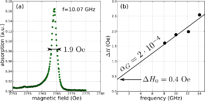
FMR also allows to extract the magnetic dynamic properties of the 200 nm thick YIG films. A typical FMR spectrum of the YIG1 film obtained at 10 GHz and low microwave power ( dBm) is presented in Fig.1a. The gyromagnetic ratio of our YIG films is found to be rad/s/Oe. From the dependence of the linewidth on the excitation frequency, their Gilbert damping can be determined, see Fig.1b. This value highlights the very small magnetic relaxation of these thin films. Still, there is an inhomogeneous part to the linewidth ( Oe in Fig.1b). For one of the two prepared films (YIG2), two to three closely spaced resonance lines could be observed in some cases, which we attribute to distinct sample regions having slightly different properties.
II.1.2 YIGPt and YIGTa bilayers
After these standard magnetic characterizations, the YIG films were cut into slabs with lateral dimensions of 1.1 mm 7 mm in order to perform inverse spin Hall voltage and magnetoresistance measurements. Platinum and tantalum thin films were then grown by sputter deposition, at a power density of 4 W/cm2. The growth of the resistive -phase Ta was achieved by optimizing the Ar-pressure during the sputtering process. The appearance of this tetragonal crystalline phase in a narrow window around mbar was verified by the presence of characteristic lines in the X-ray diffraction spectra. The -phase was also confirmed by the resistivity of the films liu12 , which for 10 nm Ta thickness lies at 200 cm.
In order to compare ISHE and SMR on YIGPt and YIGTa bilayers, a 15 nm thick Pt and a 3 nm thick Ta layers were grown on the YIG1 sample. The conductivities of these metallic films are m-1 (in agreement with the values reported in Refs.mosendz10a ; castel12a ) and m-1, respectively. These two samples have been used to obtain the results presented in Figs.2 and 4. The dependence on Pt thickness of both castel12a and magnetoresistance huang12 ; vlietstra13 has been studied earlier. In this work, we have used the YIG2 sample to study the dependence as a function of the Ta thickness, which was varied from 1.5 nm to 15 nm (1.5, 2, 3, 5, 10 and 15 nm). The conductivity of these Ta films increases from m-1 to m-1 with the film thickness. This series of samples has been used to obtain the data of Fig.3. Finally, Pt films with thicknesses 10 nm and 15 nm were also grown on YIG2, for the sake of comparison with YIG1.
II.2 Measurement setup
A 500 m wide, 2 m thick Au transmission line cell and electronics providing frequencies up to 20 GHz were used for microwave measurements. The long axis of the sample was aligned perpendicularly to the microwave line, thus parallel to the excitation field as indicated in the inset of Fig.2. was measured by a lock-in technique (with the microwave power turned on and off at a frequency of a few kHz) with electrical connections through gold leads at equal distance to the area of excitation. Magnetotransport measurements of the YIGNM slabs were performed using a 4-point configuration. The samples were placed at the center of an electromagnet, which can be rotated around its axis in order to obtain curves of magnetoresistance vs. angle. The measurement cell was placed in a cryostat, with the possibility to cool down to 77 K. All the measurements presented in this paper were performed at room temperature, except for those reported in Fig.5.
III Experimental results and analysis
III.1 Inverse spin Hall voltage: YIGPt vs. YIGTa
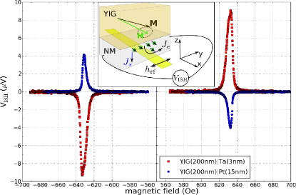
First, we compare in Fig.2 the inverse spin Hall voltages measured at 3.5 GHz ( dBm) in the YIGPt and YIGTa bilayers. It shows that one can electrically detect the FMR of YIG in these hybrid systems kajiwara10 . The spin current pumped into the adjacent normal metal by the precessing magnetization in YIG is converted into a charge current by ISHE,
| (1) |
where is the electron charge and the reduced Planck constant. This leads to a transverse voltage (across the length of the YIGNM slab), as sketched in the inset of Fig.2. Moreover, must change sign upon reversing the magnetization of YIG because of the concomitant reversal of the spin pumped current (hence ). This is observed in both the YIGPt and YIGTa systems, where is odd in applied magnetic field, which shows that the voltage generated at resonance is not due to a thermoelectrical effect.
The striking feature to be observed here is the opposite signs of in these two samples. This remains true at all microwave frequencies (from 2 to 8 GHz) and power levels (from 8 to 10 dBm) which were measured, as well as for the different YIGPt and YIGTa bilayers made from YIG1 and YIG2 samples. It thus confirms that the spin Hall angles in Ta and Pt have opposite signs, as predicted by ab initio calculations tanaka08 and inferred from measurements where the spin current was generated by a metallic ferromagnet morota11 ; liu12 . Moreover, from the electrical circuit which was used in the measurements (anode of the voltmeter is on the left in Fig.2 inset), it can be found that while . The precise estimation of the spin Hall angles in these two materials requires the more analysis presented in the following sections. Still, it is interesting to note that the 4 V amplitude of measured in Fig.2 on our 15 nm thick Pt is close to the one reported in Ref.castel12a (2 to 3 V) with comparable experimental conditions.
III.2 Dependence of inverse spin Hall voltage on Ta thickness
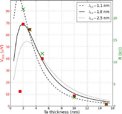
In this work, we have measured the dependence of only on Ta thickness. The study as a function of Pt thickness was already reported in Ref.castel12a , using a similar 200 nm thick YIG film (fabricated in the same lab). In Fig.3, we have plotted using red squares the dependence of on the Ta thickness measured on the series of samples described above. Here, is produced by the precession of magnetization in YIG, resonantly excited at 3.8 GHz by the microwave field ( dBm). increases from less than 2 V up to V as the Ta layer thickness is reduced from 15 nm to 2 nm, at which the maximal voltage is measured. For the thinnest Ta layer ( nm), drops to about 10 V, a value close to the one observed at nm. A similar dependence of on Pt thickness was reported in Ref.castel12a , where a maximum of voltage was observed between nm and nm.
The resistance measured across the length of the YIGTa slab is also plotted with green crosses in Fig.3 as a function of (see right scale). It is interesting to note that both and follow a similar dependence on the Ta thickness, if one excludes the thinnest Ta layer, which might be discontinuous or oxidised, and thus exhibits a very large resistance ( k is out-of-range of the graph).
To analyze the thickness dependence of the inverse spin Hall voltage, we follow the approach derived in Ref.castel12a . The spin diffusion equation with the appropriate source term and boundary conditions leads to the following expression:
| (2) | |||||
where is the conductivity of the normal metal, its thickness, the length of the YIGNM slab excited at frequency by the microwave field, the angle of precession of YIG, and an ellipticity correction factor. The latter depends on the excitation frequency mosendz10a and in our case .
From Eq.2, the amplitude of depends on the transport parameters , and , as well as on the resonant precession angle . We do not have a direct measurement of , but it can be evaluated from the strength of the microwave field and the measured linewidth gurevich96 . By performing network analyzer measurements and considering the geometry of the transmission line, we estimate the strength of the microwave field Oe for a dBm output power from the synthesizer. For the series of YIGTa samples, it yields a precession angle in YIG at 3.8 GHz. Nevertheless, the measurements presented in Fig.3 are not sufficient to extract independently and .
The thickness dependence of primarily depends on , through the argument of the exponential functions in Eq.2. The spin diffusion length can thus be adjusted to fit the shape of vs. in Fig.3. The series of lines in Fig.3 displays the result of calculations based on Eq.2 for three different values of , using the thickness dependent conductivity measured experimentally. A very good overall agreement to the data is found for a spin diffusion length nm. We explain the discrepancy observed at nm, at which the measured voltage is about five times smaller than predicted, by the fact that the thinnest Ta layer is discontinuous or oxidised, as already pointed out. We note that the spin diffusion length extracted from the YIGTa data of Fig.3 is somewhat shorter than the 2.7 nm inferred from nonlocal spin-valve measurements morota11 .
III.3 Magnetoresistance: YIGPt vs. YIGTa
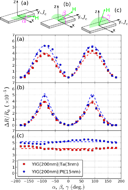
We now turn to the measurements of dc magnetoresistance in our hybrid YIGNM bilayers. We have measured the variation of resistance in the exact same samples as the ones studied by ISHE in Fig.2, YIGPt(15 nm) and YIGTa(3 nm), as a function of the angle of the applied field with respect to the three main axes of the slabs. In these experiments, the applied field was fixed to kOe (sufficient to saturate the YIG), and a dc current of a few mA together with a digits voltmeter were used to probe the resistance of the NM layers in a 4-probe configuration. The results obtained by rotating the magnetic field in the plane of the sample (angle ), from in-plane perpendicular to the charge current to out-of-plane (angle ) and from in-plane parallel to to out-of-plane (angle ) are presented in Figs.4a, 4b, and 4c, respectively (see also associated sketches).
In both the YIGPt and YIGTa bilayers, we do observe some weak magnetoresistance ( of and , respectively), as it was first reported on the YIGPt system huang12 . We checked that this weak variation does not depend on the sign or strength of the probing current. In contrast to the inverse spin Hall voltage measurements presented in Fig.2, we also note that the sign (or symmetry) of the effect is identical in YIGPt and YIGTa.
In order to interpret this magnetoresistance, it is important to understand its dependence on all three different angles, , and , shown in Fig.4. If one would just look at the in-plane behavior (Fig.4a), one could conclude that the NM resistance changes according to some anisotropic magnetoresistance (AMR) effect, as if the NM would be magnetized at the interface with YIG due to proximity effect huang12 . But with AMR, depends on the angle between the charge current and the magnetization (applied field ). Hence, no change of is expected with the angle , whereas should vary with the angle , which is exactly opposite to what is observed in Figs.4b and 4c, respectively. Therefore usual AMR as the origin of the magnetoresistance in YIGPt and YIGTa bilayers has to be excluded.
Instead, the spin Hall magnetoresistance (SMR) mechanism proposed in Ref.nakayama12 is well supported by our magnetoresistance data. In this scenario, the electrons carried by the charge current in the NM layer are deflected by SHE in opposite directions depending on their spin. Those whose spin is flipped by scattering at the interface with the FM can oppose the initial current by ISHE and lead to an increase of resistance. Therefore, the spin Hall magnetoresistance depends on the relative angle between the magnetization of the FM and the accumulated spins at the FMNM interface:
| (3) |
The increase of resistance is maximal when and are perpendicular, because the spin-flip-scattering governed by at the interface is the largest. In the geometry depicted in Fig.4, the charge current is applied along , hence the spins accumulated at the YIGNM interface due to SHE are oriented along . The dashed lines plotted in Figs.4ac are the prediction of the SMR theory. As can be seen, Eq.3 explains well the presence (absence) of resistance variation upon the applied field angles and (). Due to demagnetizing effects, the magnetization of YIG is not always aligned with the applied field. This is the reason why the measured curves in Figs.4a and 4b have different shapes, and a simple calculation gurevich96 of the equilibrium position of in combination with Eq.3 reproduces them quite well.
The SMR ratio was also calculated in Ref.nakayama12 :
| (4) |
As for the inverse spin Hall voltage (Eq.2), the SMR depends on all the transport parameters , and , which therefore cannot be extracted individually from a single measurement. In section IV.1, we will take advantage of the combined measurements of (Figs.2 and 3) and SMR (Fig.4) to do so. For now, it is interesting to point out that because both SHE and ISHE are at play in spin Hall magnetoresistance, the SMR depends on the square of the spin Hall angle. This explains the positive SMR for both YIGPt and YIGTa, even though the spin Hall angles of Pt and Ta are opposite.
Finally, it would have been interesting to measure the dependence of SMR on Ta thickness (the dependence on Pt thickness was studied in Refs.huang12 and vlietstra13 ). Unfortunately, it was difficult to realize low noise 4-point contacts to investigate the faint magnetoresistance on the series of Ta samples prepared to study vs. . From our attempts, we found that the SMR of YIGTa(10 nm) is less than . This is consistent with the decrease predicted by Eq.4 (assuming nm) with respect to the measured for YIGTa(3 nm).
IV Discussion
IV.1 Transport parameters
As already discussed, both and SMR depend on the set of transport parameters (, , ). By studying as a function of the NM thickness, the spin diffusion length can be determined, and we found that in Ta, nm, see Fig.3. We mention here that from a similar study on YIGPt, nm could be inferred castel12a . This value lies in the range of spin diffusion lengths reported on Pt, which span over almost an order of magnitude liu11b , from slightly more than 1 nm up to 10 nm.
There is a direct way to get the spin mixing conductance of a FMNM interface, by determining the increase of damping in the FM layer associated to spin pumping in the adjacent NM layer tserkovnyak05 . Due to its interfacial nature, this effect is inversely proportional to the thickness of the FM and can be measured only on ultra-thin films. This was recently achieved in nm-thick YIG films grown by pulsed laser deposition heinrich11 ; burrowes12 , where spin mixing conductances m-2 have been reported for the YIGAu interface.
| YIGTa (1.5 nm 15 nm) | YIGPt (15 nm) | |
|---|---|---|
| ( m-1) | ||
| ( m) | n/a [from 1.5 to 10]liu11b | |
| (m-2) | ||
Even for 200 nm thick YIG films as ours, it is possible to obtain the full set of transport parameters thanks to our combined measurements of and SMR on YIGNM hybrid structures. In fact, from Eqs.2 and 4, the ratio does not depend on , which allows to determine . Then, the last unknown can be found from the or SMR signal. This is how we proceed to determine the transport parameters which are collected in Table 1. The drawback of this method is that it critically relies on: i) , which enters in the argument of exponential functions in Eqs.2 and 4; and ii) the angle of precession in the inverse spin Hall experiment, since . Our estimation of being within , the value extracted for from the ratio can vary by a factor up to 8 due to this uncertainty. The spin Hall angle is less sensitive to other parameters, still it can vary by a factor up to 3. This explains the rather large error bars in Table 1. In this study, we did not determine the spin diffusion length in Pt, hence we used the range of values reported in the literature liu11b .
The spin mixing conductances determined from our combined and SMR measurements on YIGTa and YIGPt bilayers lie in the same window as the ones determined from interfacial increase of damping in YIGAu heinrich11 , from inverse spin Hall voltage in BiY2Fe5OAu and Pt takahashi12 , and from first-principles calculations in YIGAg jia11 . We would like to point out that despite the large uncertainty, for YIGTa is likely less than for YIGPt. We note that the smaller damping measured in CoFeBTa compared to CoFeBPt was tentatively attributed to a smaller spin mixing conductance liu12 .
The spin Hall angles that we report for Pt and Ta are both of a few percents. In particular, lies in between the values determined from nonlocal spin-valve measurements () morota11 and from spin-torque switching using the SHE () liu12 .
The main conclusion which arises from the summary presented in Table 1 is that the sets of transport parameters determined for the hybrid YIGTa and YIGPt systems are quite similar. Apart from the opposite sign of in Ta and Pt, the main difference concerns the conductivity: is roughly one order of magnitude smaller than . This explains the large inverse spin Hall voltages that can be detected in our YIGTa bilayers (up to 70 V at dBm), since from Eq.2 , which could be a useful feature of the Ta layer.
IV.2 Influence of a dc current on FMR linewidth
Onsager reciprocal relations imply that if there is an ISHE voltage produced by the precession of YIG, there must also be a transfer of spin angular momentum from the NM conduction electrons to the magnetization of YIG, through the finite spin mixing conductance at the YIGNM interface jia11 . Therefore, one would expect to be able to control the relaxation of the insulating YIG by injecting a dc current in an adjacent strong spin-orbit metal, as it was shown on YIGPt in the pioneering work of Kajiwara et al. kajiwara10 . Although this direct effect is well established when the ferromagnetic layer is ultra-thin and metallic ando08a ; demidov11d ; demidov12 ; liu12b , only a few works report on conclusive effects on micron-thick YIG kajiwara10 ; wang11 ; padron-hernandez11 or provide a theoretical interpretation to the phenomenon xiao12 .
The 200 nm thick YIG films that have been grown for this study are about 6 times thinner than the one used in Ref.kajiwara10 , with an intrinsic relaxation close to bulk YIG. Because the spin transfer torque is an interfacial effect and sizable spin mixing conductances have been measured in our YIGTa and YIGPt bilayers, our samples must be good candidates to observe the direct effect of a dc current on the relaxation of YIG. Due to their large resistance, -Ta films are not convenient to pass the large current densities required to observe such an effect (large Joule heating). Therefore, we have conducted these experiments only on the YIGPt films prepared in this work.
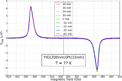
The inverse spin Hall voltage measurements presented in Fig.2 have therefore been repeated in presence of a dc current flowing through the Pt layer. This type of experiment, where a ferromagnetic layer is excited by a small amplitude signal and a spin polarized current can influence the linewidth of the resonance, has already been reported on spin-valve spin-torque oscillators sankey06 ; chen08 and NiFePt bilayers liu11 . The results obtained on our YIG(200 nm)Pt(15 nm) at 77 K when the dc current is varied from to mA are displayed in Fig.5.
Let us now comment on these experiments. We first emphasize that the current injected in Pt is truly dc (not pulsed). A sizable Joule heating is thus induced, as reflected by the increase of Pt resistance. As a consequence, the main effect of dc current injection at room temperature is the displacement of the resonance towards larger field, due to the decrease of the YIG saturation magnetization . To avoid this trivial effect, we have performed these experiments directly in liquid nitrogen. In that case, the increase of Pt resistance is very limited (% at mA). We note that when cooled from 300 K down to 77 K, the peak of the inverse spin Hall voltage measured in the YIGPt bilayer is displaced towards lower field due to the increase of of YIG (from 140 emu/cm3 up to 200 emu/cm3), and its amplitude slightly decreases.
The main conclusion that can be drawn from Fig.5 is that there is basically no effect of the dc current injected in Pt on the YIG resonance. We stress that the maximal current density reached in Pt in these experiments is A.m-2, i.e., twice larger than the one at which YIG magnetization oscillations were reported in Ref.kajiwara10 . In our experiments, we are not looking for auto-oscillations of YIG, which requires that the damping is fully compensated by spin transfer torque, but only for some variation of the linewidth. The fact that we do not see any change in the shape of the resonant peak of our 200 nm thin YIG film is thus in contradiction with the observation of bulk auto-oscillations in thicker films kajiwara10 .
We have also performed similar experiments on the other YIG(200 nm)Pt samples which were prepared using the two different YIG films grown for this study. Although the current density was increased up to A.m-2, we were never able to detect any sizable variation of the linewidth of YIG. Instead, we have measured that the dc current can affect the inverse spin Hall voltage in different ways. First, when a charge current is injected into Pt, a non-zero offset of the lock-in signal can be detected (it was subtracted in Fig.5). This is due to the increase of Pt resistance induced by the microwave power, as it was verified by monitoring this offset while varying the modulation frequency of the microwave. Secondly, the amplitude of the peaks can be affected by the dc current (but again, not the linewidth). This effect can at first be confused with some influence on the relaxation of YIG, because it displays the appropriate symmetries vs. field and current. But instead, we have found that this is a bolometric effectgui07 : when the YIG is excited at resonance, it heats up, thereby heating the adjacent Pt whose resistance gets slightly larger. Hence an additional voltage to is picked up on the lock-in due to the non-zero dc current flowing in Pt. Therefore, one should be very careful in interpreting changes in inverse spin Hall voltage as the indication of damping variation in YIG. Finally, we observed that at very large current density, the resonance peak slightly shifts towards larger field due to Joule heating, even at 77 K.
V Conclusion
In this paper, we have presented and analyzed a comparative set of data of inverse spin Hall voltage and magnetoresistance obtained on YIGPt and YIGTa bilayers. We have detected the voltages generated by spin pumping at the YIGPt interface (already well established kajiwara10 ) and at the YIGTa interface (for the first time). Their opposite signs are assigned to the opposite spin Hall angles in Pt and Ta tanaka08 . From the thickness dependence of , we have been able to obtain the spin diffusion length in Ta, nm, in reasonable agreement with the value extracted from non-local spin valve measurements morota11 . From symmetry arguments, we have shown that the weak magnetoresistance measured on our hybrid YIGNM layers cannot be attributed to usual AMR, but is instead well understood in the framework of the recently introduced spin Hall magnetoresistance (SMR) nakayama12 . By taking advantage of the combined measurements of and SMR performed on the same samples, we have been able to extract the spin Hall angles in Pt and Ta, as well as the spin mixing conductances at the YIGPt and YIGTa interfaces.
These transport parameters have all been found to be of the same order of magnitude as those already measured liu12 ; heinrich11 or predicted jia11 . We believe that at least part of the discrepancies between the parameters evaluated in different works liu11b depend on the details of the YIGNM interface burrowes12 and on the quality of the NM mosendz10a ; kondou12 ; morota11 .
Finally, we could not detect any change of linewidth in our YIGPt samples by passing large current densities through the Pt layer. One might argue that our high quality 200 nm YIG thin films are still too thick to observe any appreciable effect of spin transfer torque, which is an interfacial mechanism, or that the spin-waves which can auto-oscillate under the action of spin transfer at the interface with Pt are different from the uniform mode that we excite with the microwave field in our experiments kajiwara10 ; xiao12 . If one would estimate the threshold current required to fully compensate the damping of all the magnetic moments contained in our YIG films liu12 ; xiao12 , , one would get current densities of about A.m-2. This is 20 times larger than the largest current density which we have tried. Thus the lack of a visible effect in our Fig.5 is not a real surprise in itself, but it is inconsistent with the results reported in Ref.kajiwara10 . Future experiments on ultra-thin YIGNM hybrid films, in which the spin mixing conductance can be directly determined from the interfacial increase of damping heinrich11 , might give a definite answer to this point.
Acknowledgements.
This research was supported by the French ANR Grant Trinidad (ASTRID 2012 program).References
- (1) V. I. Dyakonov, M. I. & Perel, JETP Lett. 13 (1971)
- (2) J. E. Hirsch, Phys. Rev. Lett. 83, 1834 (1999)
- (3) S. O. Valenzuela and M. Tinkham, Nature (London) 442, 176 (2006)
- (4) T. Kimura, Y. Otani, T. Sato, S. Takahashi, and S. Maekawa, Phys. Rev. Lett. 98, 156601 (2007)
- (5) E. Saitoh, M. Ueda, H. Miyajima, and G. Tatara, Appl. Phys. Lett. 88, 182509 (2006)
- (6) Y. Kajiwara, K. Harii, S. Takahashi, J. Ohe, K. Uchida, M. Mizuguchi, H. Umezawa, H. Kawai, K. Ando, K. Takanashi, S. Maekawa, and E. Saitoh, Nature (London) 464, 262 (2010)
- (7) Y. Tserkovnyak, A. Brataas, G. E. W. Bauer, and B. I. Halperin, Rev. Mod. Phys. 77, 1375 (2005)
- (8) H. Nakayama, M. Althammer, Y.-T. Chen, K. Uchida, Y. Kajiwara, D. Kikuchi, T. Ohtani, S. Geprägs, M. Opel, S. Takahashi, R. Gross, G. E. W. Bauer, S. T. B. Goennenwein, and E. Saitoh, arXiv:1211.0098(2012)
- (9) K. Ando, Y. Kajiwara, S. Takahashi, S. Maekawa, K. Takemoto, M. Takatsu, and E. Saitoh, Phys. Rev. B 78, 014413 (2008)
- (10) A. Azevedo, L. H. Vilela-Leão, R. L. Rodríguez-Suárez, A. F. Lacerda Santos, and S. M. Rezende, Phys. Rev. B 83, 144402 (2011)
- (11) Z. Feng, J. Hu, L. Sun, B. You, D. Wu, J. Du, W. Zhang, A. Hu, Y. Yang, D. M. Tang, B. S. Zhang, and H. F. Ding, Phys. Rev. B 85, 214423 (2012)
- (12) O. Rousseau and M. Viret, Phys. Rev. B 85, 144413 (2012)
- (13) C. W. Sandweg, Y. Kajiwara, K. Ando, E. Saitoh, and B. Hillebrands, Appl. Phys. Lett. 97, 252504 (2010)
- (14) H. Kurebayashi, O. Dzyapko, V. E. Demidov, D. Fang, A. J. Ferguson, and S. O. Demokritov, Nature Mater. (London) 10, 660 (2011)
- (15) L. H. Vilela-Leão, C. Salvador, A. Azevedo, and S. M. Rezende, Appl. Phys. Lett. 99, 102505 (2011)
- (16) A. V. Chumak, A. A. Serga, M. B. Jungfleisch, R. Neb, D. A. Bozhko, V. S. Tiberkevich, and B. Hillebrands, Appl. Phys. Lett. 100, 082405 (2012)
- (17) V. Castel, N. Vlietstra, J. Ben Youssef, and B. J. van Wees, Appl. Phys. Lett. 101, 132414 (2012)
- (18) O. Mosendz, V. Vlaminck, J. E. Pearson, F. Y. Fradin, G. E. W. Bauer, S. D. Bader, and A. Hoffmann, Phys. Rev. B 82, 214403 (2010)
- (19) K. Kondou, H. Sukegawa, S. Mitani, K. Tsukagoshi, and S. Kasai, Appl. Phys. Express 5, 073002 (2012)
- (20) L. Liu, C.-F. Pai, Y. Li, H. W. Tseng, D. C. Ralph, and R. A. Buhrman, Science 336, 555 (2012)
- (21) C.-F. Pai, L. Liu, Y. Li, H. W. Tseng, D. C. Ralph, and R. A. Buhrman, Appl. Phys. Lett. 101, 122404 (2012)
- (22) S. Y. Huang, X. Fan, D. Qu, Y. P. Chen, W. G. Wang, J. Wu, T. Y. Chen, J. Q. Xiao, and C. L. Chien, Phys. Rev. Lett. 109, 107204 (2012)
- (23) M. Morota, Y. Niimi, K. Ohnishi, D. H. Wei, T. Tanaka, H. Kontani, T. Kimura, and Y. Otani, Phys. Rev. B 83, 174405 (2011)
- (24) T. Tanaka, H. Kontani, M. Naito, T. Naito, D. S. Hirashima, K. Yamada, and J. Inoue, Phys. Rev. B 77, 165117 (2008)
- (25) X. Jia, K. Liu, K. Xia, and G. E. W. Bauer, Europhys. Lett. 96, 17005 (2011)
- (26) L. Liu, R. A. Buhrman, and D. C. Ralph, arXiv:1111.3702v3(2011)
- (27) V. Castel, N. Vlietstra, B. J. van Wees, and J. Ben Youssef, Phys. Rev. B 86, 134419 (2012)
- (28) N. Vlietstra, J. Shan, V. Castel, J. Ben Youssef, and B. J. van Wees, arXiv:1301.3266(2013)
- (29) A. G. Gurevich and G. A. Melkov, Magnetization Oscillations and Waves (CRC Press, 1996)
- (30) B. Heinrich, C. Burrowes, E. Montoya, B. Kardasz, E. Girt, Y.-Y. Song, Y. Sun, and M. Wu, Phys. Rev. Lett. 107, 066604 (2011)
- (31) C. Burrowes, B. Heinrich, B. Kardasz, E. A. Montoya, E. Girt, Y. Sun, Y.-Y. Song, and M. Wu, Appl. Phys. Lett. 100, 092403 (2012)
- (32) R. Takahashi, R. Iguchi, K. Ando, H. Nakayama, T. Yoshino, and E. Saitoh, J. Appl. Phys. 111, 07C307 (2012)
- (33) K. Ando, S. Takahashi, K. Harii, K. Sasage, J. Ieda, S. Maekawa, and E. Saitoh, Phys. Rev. Lett. 101, 036601 (2008)
- (34) V. E. Demidov, S. Urazhdin, E. R. J. Edwards, M. D. Stiles, R. D. McMichael, and S. O. Demokritov, Phys. Rev. Lett. 107, 107204 (2011)
- (35) V. Demidov, S. Urazhdin, H. Ulrichs, V. Tiberkevich, A. Slavin, D. Baither, G. Schmitz, and S. O. Demokritov, Nature Mater. (London) 11, 1028 (2012)
- (36) L. Liu, C.-F. Pai, D. C. Ralph, and R. A. Buhrman, Phys. Rev. Lett. 109, 186602 (2012)
- (37) Z. Wang, Y. Sun, M. Wu, V. Tiberkevich, and A. Slavin, Phys. Rev. Lett. 107, 146602 (2011)
- (38) E. Padrón-Hernández, A. Azevedo, and S. M. Rezende, Appl. Phys. Lett. 99, 192511 (2011)
- (39) J. Xiao and G. E. W. Bauer, Phys. Rev. Lett. 108, 217204 (2012)
- (40) J. C. Sankey, P. M. Braganca, A. G. F. Garcia, I. N. Krivorotov, R. A. Buhrman, and D. C. Ralph, Phys. Rev. Lett. 96, 227601 (2006)
- (41) W. Chen, J.-M. L. Beaujour, G. de Loubens, A. D. Kent, and J. Z. Sun, Appl. Phys. Lett. 92, 012507 (2008)
- (42) L. Liu, T. Moriyama, D. C. Ralph, and R. A. Buhrman, Phys. Rev. Lett. 106, 036601 (2011)
- (43) Y. S. Gui, N. Mecking, A. Wirthmann, L. H. Bai, and C.-M. Hu, Appl. Phys. Lett. 91, 082503 (2007)