∎
Members of “Carrera del Investigador Científico of CONICET”
33email: rovero@iafe.uba.ar 44institutetext: P. Ringegni 55institutetext: G. Vallejo 66institutetext: M. Actis 77institutetext: A. Botani 88institutetext: I. Ochoa 99institutetext: Unidad de Investigación y Desarrollo GEMA, Ingeniería Aeronáutica (UNLP), Argentina
99email: ringegni@ing.unlp.edu.ar 1010institutetext: G. Hughes 1111institutetext: Deutsches Elektronen-Synchrotron (DESY), Zeuthen, Germany
Design of a 7m Davies-Cotton Cherenkov telescope mount for the high energy section of the Cherenkov Telescope Array
Abstract
The Cherenkov Telescope Array is the next generation ground-based observatory for the study of very-high-energy gamma-rays. It will provide an order of magnitude more sensitivity and greater angular resolution than present systems as well as an increased energy range (20 GeV to 300 TeV). For the high energy portion of this range, a relatively large area has to be covered by the array. For this, the construction of 7 m diameter Cherenkov telescopes is an option under study. We have proposed an innovative design of a Davies-Cotton mount for such a telescope, within Cherenkov Telescope Array specifications, and evaluated its mechanical and optical performance. The mount is a reticulated-type structure with steel tubes and tensioned wires, designed in three main parts to be assembled on site. In this work we show the structural characteristics of the mount and the optical aberrations at the focal plane for three options of mirror facet size caused by mount deformations due to wind and gravity.
Keywords:
CTA Gamma-rays Imaging Atmospheric Cherenkov Telescope Telescope Optics Telescope AberrationsTelescope Mechanical Mountpacs:
95.55ka 92.15Fr1 Introduction
The present generation of ground-based observatories like HESS, MAGIC and VERITAS have led the field of very-high-energy gamma-ray astronomy for the last few years, achieving great success through significantly increasing the rate of source discovery and making detailed observations on many interesting objects. The international scientific community is now organizing the next generation of ground-based instruments, the Cherenkov Telescope Array (CTA). With sensitivity an order of magnitude better than present systems and improved angular resolution, CTA will observe the full sky by constructing two observatories, one in each hemisphere, covering an extended energy range (20 GeV to 300 TeV) (Actis et al. 2011). To span such a large energy range, three different sizes of Cherenkov telescope will potentially be constructed. Large size telescopes (LSTs) and medium size telescopes (MSTs) are under study to cover the low and intermediate energy range, respectively. Small size telescopes (SSTs) will be used to cover a large area (about 10 km2) and detect the highest energy gamma rays (1 TeV), for which a 3-4 m diameter mirror is required as reflecting area for each SST.
Two types of optical system are being considered for the SST, Schwarzschild-Couder (SC) (Vassiliev et al. 2007) and Davies-Cotton (DC) (Lewis 1990). The first of these, with primary and secondary mirrors, has short focal length and hence a reduced plate scale which translates into a small camera. Two SC designs have been proposed for the SST (White et al. 2011) whose reliability will be investigated using the prototypes that are currently under construction. The DC design has a simpler structure and mirrors and is already proven, as it is the type of telescope used by present experiments. The camera required is, however, larger and potentially more expensive. To balance the costs of the camera and mount, a first alternative was considered for the DC design, i.e. to cover the area of 10 km2 with fewer SSTs with a relatively large mirror area. Based on past experience and Monte Carlo simulations, it was specified that this alternative should have a 6-7 m diameter tessellated reflecting surface (dish). The dish would be an array of hexagonal facets, each with three mounting points, two of them with actuators to align the mirror. The detector at the focal plane is an array of 1400 photomultipliers, each of 0.25∘ angular diameter, at a focal distance 11 m, covering a field of view (f.o.v.) of 8-10∘. The Point Spread Function (PSF) for the SST has to be less than the angular size of the camera pixel. A new type of DC SST is also under consideration using the FACT camera approach (Bretz et al. 2011), which uses cheaper solid photodetectors and thus allows a reasonable cost balanced to be achieved. This telescope uses a smaller dish of diameter about 4 m.
All the characteristics mentioned above for the SST, and other similar ones for the MST and the LST, were specified by the CTA Consortium based on previous experience and the science requirements. Considering these specifications, MC simulations are being performed to determine which is the best combination of telescope types and parameters for the array that will optimize the science needs. Meanwhile, any proposed telescope has to fulfill the general characteristics required for the relevant telescope type.
We have proposed an innovative design of Davies-Cotton mount for the SST of CTA and evaluated its mechanical and optical performance under both operational and extreme conditions. The first approach used a 6 m dish (Actis et al. 2010, Rovero et al. 2011). Following this experience, the decision was made to enlarge the dish to 7 m diameter and use more regular layouts for the facets, for which a better optimized mount was obtained. In this work we present the final mechanical design of a 7 m DC mount and the study of the optical aberrations related to mount deformations for three different mirror facet sizes and under various telescope operating conditions.
2 Telescope mount: mechanical design
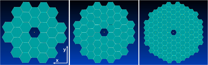
Considering the general specifications for the SST optical system, a pixel size of 50 mm and a focal length of 11.46 m were adopted, resulting in an 1.65 and a pixel angular diameter of 0.25∘. The focal plane was designed for a camera with maximum f.o.v. of 10∘. For the construction of a 7 m dish, hexagonal mirror facets of three sizes () were considered, = 60, 90 and 120 cm from flat to flat (i.e. twice the apothem). Figure 1 shows the dish layouts considered for the mount design, which are hexagonal arrays of mirrors with the facets at the corners removed to make the dish more circular and to reduce optical aberrations. The mirrors are mounted on a spherical surface (following the DC concept) with a spacing of 2 cm to avoid contact between facets. In Table 1, the number of facets and the total reflecting area for each dish layout are shown. Also shown in the table is an estimation of effective area considering the shadowing of the structure and a 2 m diameter camera.
| Mirror size [cm] | Number of facets | Total mirror area [m2] | Effective area [m2] |
|---|---|---|---|
| 120 | 30 | 37.4 | 32.2 |
| 90 | 54 | 37.9 | 32.1 |
| 60 | 120 | 37.4 | 31.3 |
The main mechanical requirements established by CTA for the SST mount are summarized in Table 2. To avoid resonance phenomena the eigen frequencies of the structure are required to be greater than 2.5 Hz. Under emergency wind speed, the telescope has to be able to drive to the parking position, in which the structure should resist the survival wind speed.
| Parameter | Condition |
|---|---|
| Eigen frequencies | 2.5 Hz |
| Positioning speed, azimuth | 180 ∘/min |
| Positioning speed, elevation | 90 ∘/min |
| Acceleration, azimuth | 1 ∘/sec2 |
| Acceleration, elevation | 0.5 ∘/sec2 |
| Tracking precision | 6 arcmin |
| Pointing precision | 10 arcsec |
| Temperature range, operational | -10 ∘C, 30 ∘C |
| Temperature range, survival | -15 ∘C, 60 ∘C |
| Wind speed, operational | 50 km/h |
| Wind speed, emergency | 100 km/h |
| Wind speed, survival | 180 km/h |
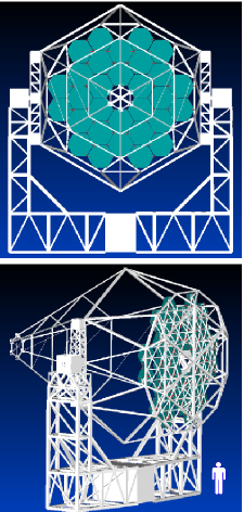
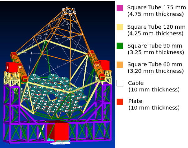
The mount designed is a reticulated-type structure with square cross section tubes of F-24 steel (low carbon) and tensioned wires (see Fig. 2). For simplicity, tubes are reduced to 4 different cross section sizes. The structure consists of three different parts: the azimuthal or lower structure; the elevation or upper structure; and the mirror support structure. Each has its own requirements and resulting mechanical solutions. For the azimuthal structure, the fact that it will be exposed mainly to flectional and torsional forces, determines leads to the adoption of a space truss whose main components are welded structural tubes. With ease of transport in mind, the azimuthal structure is expected to be built in three sections, two vertical and one horizontal truss. A single central shaft with pinion and crown located at the bottom of this structure provides the azimuthal movement. The elevation mount consists of a truncated pyramid with a hexagonal base, in which each face is a truss with cordons and uprights consisting of structural tubes and tensioners. It becomes complete with two drawer trusses on the sides to transmit the forces through the shafts to the azimuthal structure. Finally, the mirror support structure is a two-layer stereo structure of hexagonal shape. It completes the previous structure and fulfills the dual purpose of supporting the load of the mirrors and wind’s action on them, also providing a stiffening plane in the elevation structure. The mirror support structure is the only part of the mount to be modified according to the chosen dish layout. Elevation and azimuth double drive systems were adopted to improve structure movements and better resist wind moments. Servomotors in all shafts give constant torque at low speed.
Structural analysis, including buckling, was carried out to design the mount and to have good safety margins. The hypotheses assumed for the Finite Element Model are:
-
•
Linear-elastic behavior.
-
•
Isotropic Material, Young’s Modulus 2.11011 Pa, Poisson’s Modulus 0.32, density 7800 kg m-3.
-
•
Truss and Shaft simulated by beam elements.
-
•
Sheet metal parts (truss-shaft links) simulated by plate elements.
-
•
Tensioners simulated by rod elements.
-
•
Mirrors simulated by mass elements, located on the tips of the truss-mirror links.
-
•
Camera simulated by mass elements, located on 6 points of the camera-truss link structure.
-
•
For simulations it is considered that shafts are impelled of relative movements with linkages.
-
•
Camera mass of 1600 kg and a mirror mass of 33 kg m-2.
-
•
Body load of 9.81 m s-2 applied to simulate gravity.
-
•
Wind loads on structure simulated by force per length unit.
-
•
Wind loads on mirrors simulated by single forces on the tips of mirror linkages.
-
•
Wind on sheet metal parts simulated by force per unit area (dynamic pressure).
-
•
Nodes on the bottom of the sheet metal parts of the azimuthal structure with pinned constraints.
-
•
Total mass of azimuthal structure of 8900 kg (28,984 elements).
-
•
Total mass of elevation structure of 4400 kg (9154 elements).
-
•
Total mass of mirror support structure of 1200 kg (3300 elements).
-
•
Total mass of elevation shafts of 780 kg (40 elements).
Simulations were carried out for three cases: normal operation, positioning, and parking. For normal operation, the tracking ability of the system is tested considering all loads under maximum operational wind speed (50 km/h). Structure deformations are computed for all possible elevation angles and used to verify the optical performance (see Section 3). The positioning case is the critical operational condition for the structure mechanisms and drives. It simulates the situation of positioning the telescope from any given point to the parking position under a critical wind speed of 100 km/h. Maximum shaft moments were found to be 60,000 N m for the elevation shaft (30,000 N m each) and 42,000 N m for the azimuth shaft. The parking (or survival) case is the critical situation that ensures the structural integrity of the telescope. It considers winds of 180 km/h and allows the dimensioning of the structural components. The result of this simulation gave a security margin of 1.97 for maximum stresses, and 1.83 for the elasto-plastic behavior analysis. A fourth case was considered to check the first natural frequency of the system, which was estimated to be 3.2 Hz (second natural frequency 4 Hz).
The final step in the design process is to perform a detailed engineering of the mount. After this is complete, an optimization of the costs for both the prototype and the production telescope mount will be possible. The CTA Consortium is still performing the studies to decide what the final array would be and, in particular, what type of SST should be adopted. Once these studies are concluded, an optimization of the costs will be a necessity.
3 Optical Aberrations
Optical aberrations are related to the dispersion of photons collected at the focal plane. As a measure of such dispersion, the diameter of a circle containing 80 % of the collected light at the focal plane is considered (herein denoted D80). To test the optical aberrations of the telescope mount, no consideration is given to the intrinsic aberrations of mirror facets, i.e. the roughness and mirror deformations are not taken into account. We have performed the analysis of optical aberrations for our design in two steps, firstly studying system aberrations for the dish layouts proposed in the previous section, and secondly we have considered the contribution of mechanical deformations as obtained in Section 2 from simulations under normal operation.
3.1 System aberrations
The intrinsic aberration of several wide-field optical systems available for IACTs have been studied previously (e.g. Schliesser & Mirzoyan 2005). DC optical systems are known to have relatively low aberrations for large off-axis incidence angles, which depend on the layout of the facets for the dish under consideration. Here we compute the optical aberrations specifically for the mirror layouts proposed for our DC design and by computing D80 instead of the commonly used PSF (i.e. the RMS of the photon distribution at the focal plane for each axis). This also allows us to estimate the aberrations caused by structure deformations by comparison with intrinsic system aberrations (Section 3.2).
The arrays of hexagonal facets (Figure 1) are mounted on a spherical structure with radius of curvature = 11.46 m, i.e. equal to the focal length. Each facet is a spherical mirror with radius 2, following the DC design (Lewis 1990). In our coordinate system the center of the dish is placed at the point (0,0,-R), i.e. the origin is at the center of the focal plane (camera), is the optical axis, is parallel to the Earth’s surface, and is perpendicular to both, as shown in Figure 1. The direction of any incident photon is defined by two angles relatively to the -axis: in the plane (azimuth) and in the plane (elevation). We describe the reflected photon using the angles and . Thus, the incident and reflected photons are characterized by and , respectively.
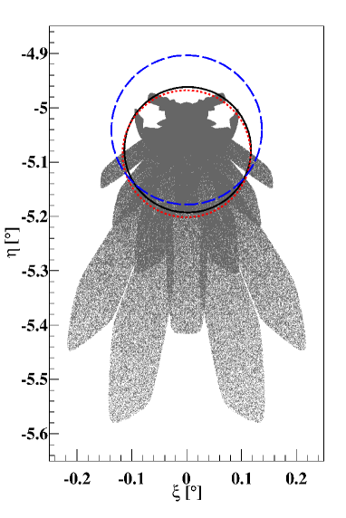
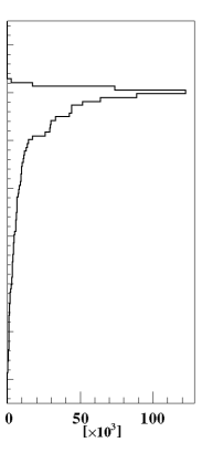
Given the incidence of a parallel photon beam on the dish, a non-pointlike distribution of reflected photons is formed at the focal plane due to system aberrations. To characterize this distribution we used our own MC ray-tracing code for 106 photons homogeneously distributed over the dish. An example of such a distribution at the focal plane is shown in Figure 3, for the dish formed by 30 120 cm facet mirrors, and for a rather extreme angle of incidence, . In the same figure, the distribution on the elevation axis is shown, indicating the strong concentration of reflected photons at the specular position (). The shape of the distribution is typical for a DC telescope.
The definition of D80 given above (Section 3) is not unique. The most intuitive interpretation would be to take the diameter of a circle centered at that encloses 80 % of the photons (), or to take the median as the circle center (). The smallest possible values of D80 are obtained by choosing the position of the circle in the focal plane that minimizes its diameter (). Figure 3 shows these cases for the particular distribution shown in the figure. We have obtained D80 using these three definitions for incidence angles on different planes and shown elsewhere (Rovero et al. 2011) that is slightly better than , although the latter could be taken as a very good approximation. In this work we use .
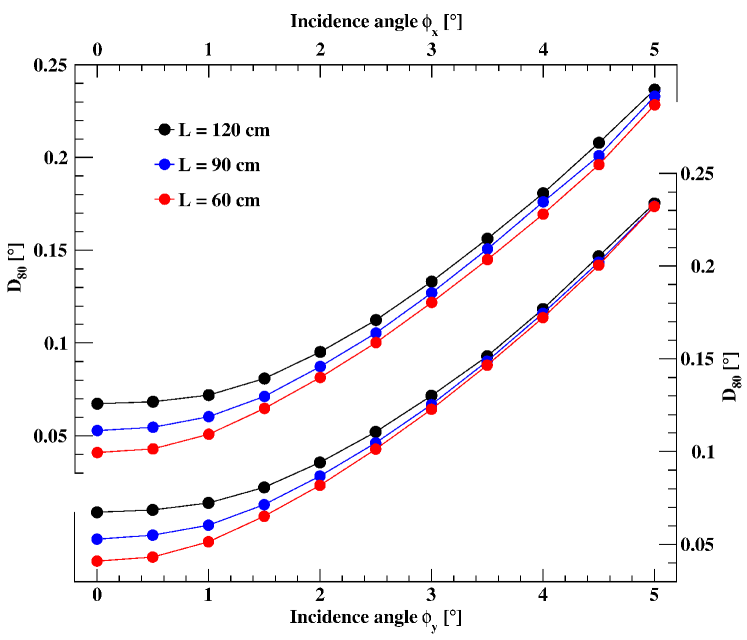
Figure 4 shows the results of the simulations, where two sets of curves are presented, corresponding to incidence angles in the azimuth () and the elevation () planes. The small differences in the behavior of the curves reflect the fact that the dishes are not perfectly symmetrical. The curves indicate that reducing the facet size improves the general performance, as expected, although for angles the system aberrations are similar for incidence in the elevation plane. Uncertainties in the estimation of should, in principle, be computed by evaluating the minimization procedure used to find in each case. Values of including uncertainties are always below the pixel size (0.25∘) even for the maximum proposed field of view (10∘) and, consequently, within specifications.
3.2 Including mechanical deformations
Telescope mount deformations cause mirror facets to change their orientation and, consequently, to change the photon distribution at the focal plane. As only structural deformations are considered here, the procedure used was to evaluate the displacements of the positions of the facet mounting points relative to their ideal positions using the simulation code outlined in Section 2. Once the new displaced positions of the mirror facets were found, ray-tracing was used to find the new including mechanical deformations.
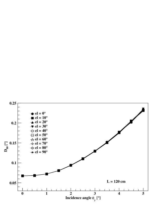
We have calculated the optical aberration in the worst possible case for all three dish layouts of Figure 1, by estimating including structural deformations as described above. The worst possible case means under the most extreme wind speed conditions considered for telescope operation, i.e. 50 km/h, hitting from the most disadvantageous angle on the structure. We have done this for both photon incidence angles, and . Gravity causes structural deformations to depend on elevation angle, so we have computed the system performance as a function of telescope elevation. As an example, Figure 5 shows under these conditions for elevations 0∘ to 90∘, in steps of 10∘. No significant degradation of the optical performance is apparent in the example due to mechanical deformations for our mount design. To better appreciate the influence of structural deformations, Figure 6 shows the differences in percentage of compared to the aberrations without mechanical deformations. The figure shows all cases under consideration: and for = 60, 90, and 120 cm.
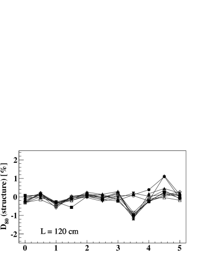
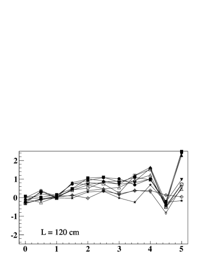
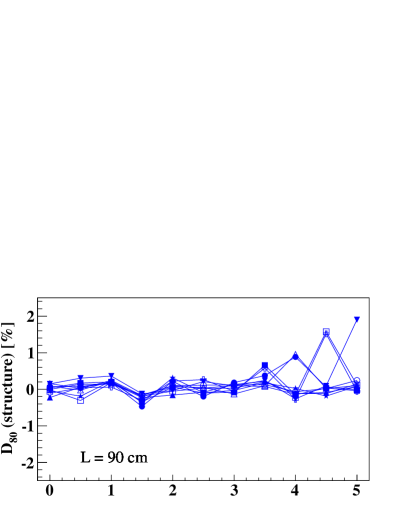
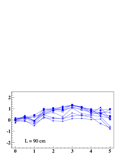
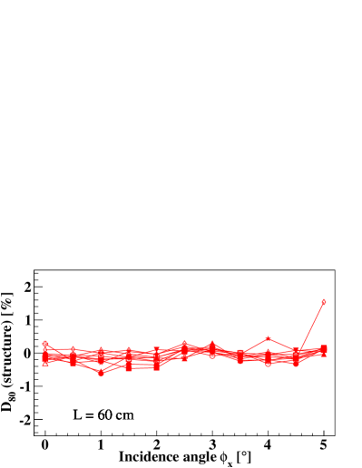
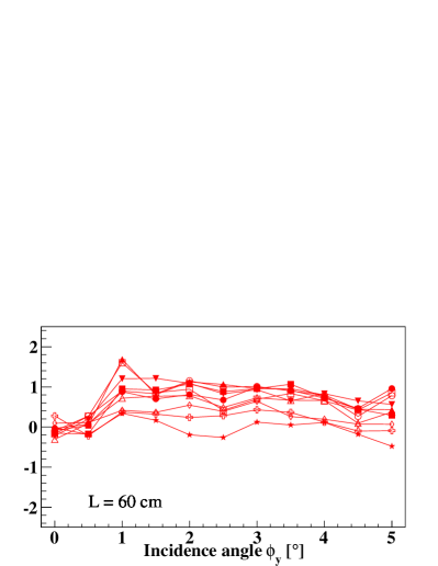
Even for the worst case of telescope operation, Figure 6 shows that elevation angle is not relevant for the telescope’s optical performance. Within the large field of view under consideration for the SST (10∘), the deterioration of the optical performance due to mechanical deformations remains typically within 1 %, with an apparent improvement for small incidence angles, being the largest deviation 2.5 %. Then, the overall telescope optical aberrations are, within few percent, the system aberrations as shown in Figure 4.
4 Summary
We have proposed a design for a 7 m Davies-Cotton mount for the Small Size Telescope of CTA, and have evaluated how optical performance is affected by mount deformations for three mirror facet sizes. The mount designed is a reticulated-type structure with square cross-section steel tubes and tensioned wires. The structure consists of three different parts, the azimuthal, the elevation, and the mirror support structures. Assuming linear-elastic behavior, a Finite Element Model was used to design the mount components and to evaluate safety margins. Simulations were performed for three cases: normal operation, positioning, and parking. For normal operation (wind speed 50 km/h) the structure deformations were computed for all possible elevation angles and used to evaluate the optical performance. The positioning case (wind speed 100 km/h) simulates the situation of driving the telescope from any point to the parking position which allowed the design of the shafts and drives. The parking (or survival) position ensures the structural integrity of the telescope under the worst conditions (wind speed 180 km/h). The result of this simulation gave a security margin of 1.97 for maximum stresses, and 1.83 for the elasto-plastic behavior analysis. The first natural frequency of the system was estimated to be 3.2 Hz.
Optical aberrations were computed using our own MC ray-tracing to evaluate the system aberrations and the contribution to the aberrations caused by mechanical deformations as a function of elevation angle for three dish layouts using hexagonal mirror facets of 120 cm, 90 cm, and 60 cm. As a measure of optical aberrations we evaluated the diameter of the smallest circle containing 80 % of the photons collected by the system at the focal plane. Our results show that aberrations are lower for smaller mirror facets, in particular for small incidence angles, although the differences are not significant. Mechanical deformations do not significantly change the optical performance. Variations in the aberrations due to this effect are within 1 % for most incidence angles, with an apparent improvement for small angles, being the largest deviation 2.5 %. Even considering this extreme case, the aberrations estimated for our design are always smaller than the pixel size (0.25∘) and, within few percent, well described by the system aberrations (without considering mechanical deformations). This conclusion applies for the worst possible case of telescope operation and for any telescope elevation angle. It suggests that our mount design might be more rigid than necessary. Considering that the telescope cost has yet to be studied for our design, one could imagine relaxing the mechanical tolerances to make the structure cheaper, while still keeping the deformations within specifications. However, the current rigidity of the structure is in response to the mechanical requirements outlined in Section 2. Of particular importance is the survival condition, where the security margin is slightly smaller than a factor two. While this margin is reasonable, it prevents a significant relaxation of the tolerances.
Acknowledgements.
We thank to the anonymous Referee for very helpful comments. We gratefully acknowledge support from the agencies and organisations listed in this page: http://www.cta-observatory.org/?q=node/22.References
- (1) Actis, M., et al.: Diseño de montura Davies-Cotton de telescopio Cherenkov de 6m de diámetro para el proyecto CTA. BAAA 53, 207-210 (2010)
- (2) Actis, M., et al.: Design concepts for the Cherenkov Telescope Array: an advanced facility for ground-based high-energy gamma-ray astronomy. Experimental Astronomy 32, 193-316 (2011)
- (3) Bretz, T., et al.: Status of the First G-APD Cherenkov Telescope (FACT). 32nd ICRC, Vol 9, 202-205 (2011)
- (4) Lewis, D.A.: Optical characteristics of the Whipple Observatory TeV gamma-ray imaging telescope. Experimental Astronomy 1, 213-236, (1990)
- (5) Rovero, A.C., et al.: Optical performance related to mechanical deformations of a Davies-Cotton mount for the high energy section of the Cherenkov Telescope Array. 32nd ICRC, Vol 9, 46-49 (2011)
- (6) Schliesser, A., Mirzoyan, R.: Wide-field prime-focus imaging atmospheric Cherenkov telescopes: A systematic study. Astroparticle Physics 24, 382-390 (2005)
- (7) Vassiliev, V., Fegan, S.J., Brousseau, P.: Wide field aplanatic two-mirror telescopes for ground-based gamma-ray astronomy. Astroparticle Physics 28, 10-17 (2007)
- (8) White, R., et al.: Telescopes for the High Energy Section of the Cherenkov Telescope Array. 32nd ICRC, Vol 9, 58-61 (2011)