SURF imaging beams in an aberrative medium: generation and postprocessing enhancement
Abstract
This paper presents numerical simulations of dual-frequency second-order ultrasound field (SURF) reverberation suppression transmit-pulse complexes. Such propagation was previously studied in a homogeneous medium. Here instead the propagation path includes a strongly aberrating body-wall modeled by a sequence of delay-screens. The applied SURF transmit pulse complexes each consist of a high-frequency imaging 3.5 MHz pulse combined with a low-frequency 0.5 MHz sound speed manipulation pulse. Furthermore, the feasibility of two signal post-processing methods are investigated using the aberrated transmit SURF beams. These methods are previously shown to adjust the depth of maximum SURF reverberation suppression within a homogeneous medium. The request of the study arises because imaging situations where reverberation suppression is useful are also likely to produce pulse wave-front distortion (aberration). Such distortions could potentially produce time-delays that cancel the accumulated propagation time-delay needed for the SURF reverberation suppression technique. Results show that both the generation of synthetic SURF reverberation suppression imaging transmit-beams, and the following post-processing adjustments, are attainable even when a body-wall introduces time-delays which are larger than previously reported delays measured on human body-wall specimens.
The peer-reviewed version of this paper is published
in IEEE Transactions on Ultrasonics, Ferroelectrics
and Frequency Control, vol. 59, no. 11, pp. 2588-2595,
November 2012. DOI: 10.1109/TUFFC.2012.2494
The final version is available online at
http://dx.doi.org/10.1109/TUFFC.2012.2494 The current
e-print is typeset by the authors and differs in e.g.
pagination and typographic detail.
I Introduction
This work concerns dual-frequency transmit-beams that are utilized for reverberation noise suppression in ultrasound image reconstruction by use of methods analyzed in [1, 2]. The developments of the current paper regard the feasibility of such beam generation within an inhomogeneous medium that generates sound-speed variations that aberrate the beam. Although the subject is connected, here we don’t apply or develop aberration correction algorithms.
The quality of medical ultrasound images varies greatly between patients. Spatial inhomogeneities in compressibility and density within the ultrasound propagation path cause additive reverberation (multiple scattering) noise, as well as resolution degradation due to wave-front distortion (aberration). This is especially prominent when imaging through e.g. the abdominal wall or the chest wall of obese patients [3, 4, 5, 6, 7]. A recent simulation study supports the hypothesis that the image degradation due to reverberation noise is more prevalent than degradation due to aberration noise [8, 9].
In dual-frequency second-order ultrasound field (SURF) reverberation-suppression imaging, a synthetic transmit-beam is generated from the difference between two high-frequency (HF) imaging pulses transmitted in the same direction. This beam is in the following simply denoted the SURF beam. Both transmissions comprise a dual-frequency band pulse-complex with the HF part used for image reconstruction, added to a low-frequency (LF) part used for material compressibility manipulation. The high frequency is typically of the order 10 times the low frequency. The compressibility is pressure-dependent due to material nonlinearity. This makes the sound-speed pressure-dependent, being higher for the compressed medium than for the expanded medium [10]. The LF polarity is switched for the second transmission, therefore making the LF pressure experienced by the second HF pulse opposite what was experienced by the first HF pulse. The pressure-dependent sound-speed thus causes the two HF pulses to propagate at different speeds. With increasing distance traveled, the difference in propagation-time required for the two HF pulses hence increases. Consequently, the difference obtained when subtracting the HF pulses is zero at zero depth and grows with covered distance to attain a maximum at 180∘ phase-shift. This is the effect that is exploited for reverberation suppression as follows. The SURF beam is the synthetic transmit-beam obtained when subtracting the propagated HF pulses at each spatial position. The amplitude of scattered (or reflected) pulses are severely reduced, hence making the nonlinear sound-speed manipulation negligible. Therefore scattered HF parts accumulate less relative time-shift than forward-propagating ones. Especially when the first scattering takes place at shallow depths, multiple scattered contributions within the received HF pulses thus give negligible contribution to the receive SURF difference HF field. The reverberation suppression ability of SURF imaging is illustrated by the fact that the beam is reduced near the transducer, as was studied in [1] where nonlinear numerical propagation simulations in a homogeneous medium were reported. In addition, the combination of tissue-harmonic pulse-inversion with SURF reverberation suppression was introduced.
In case the dominating reverberation noise is due to a strong first scattering (reflection) taking place around a depth , the SURF synthetic transmit field may without modification or re-transmission of the sent-out pulses, be adjusted to increase the transmit-beam suppression around by use of post-processing methods as described and analyzed in [2] for a homogeneous medium. Both multiple scattering and multiple reflection image artifacts are in the following considered as reverberation artifacts. The recent publications [11, 12, 13] concern SURF dual-frequency acoustics within a wider context. Dual frequency band pulse complexes have also been used for contrast agent detection [14, 15, 16, 17, 18, 19].
The purpose of the computer simulation study presented in the current paper is to evaluate the feasibility of SURF transmit reverberation suppression beam generation when a strongly aberrative body-wall is present within the wave-propagation path. Furthermore, it intends to compare these SURF beams to standard fundamental imaging transmit-beams, and in addition to test the post-processing SURF transmit field enhancement techniques described in [2] in case of aberration.
The study is important because the body-wall of a patient where standard fundamental ultrasound imaging is aggravated due to reverberation noise, is also likely to produce propagation time-shifts due to aberration. If these time-shifts heavily distort the accumulated time-shifts needed for adequate SURF synthetic beam generation, the reverberation suppression gain of the SURF imaging method is no longer obtained.
This paper is organized as follows: First the dual-frequency SURF imaging and fundamental imaging excitation pulses used in the numerical simulations are presented. Then a description of the body-wall model and field simulation method is given. The results section shows comparisons between transmit-beams from the described excitation pulses both for a homogeneous medium and after propagation through the body-wall. Beam profiles in the focal plane are derived from the transmit-beams, to quantify the effect the body-wall has on the transmit field. Finally, post-processing adjusted SURF transmit-beams are constructed for some chosen example depths of decreased transmit-beam amplitude.
II Theory and Methods
II-A Excitation pulses
The two excitation pulses utilized to generate the SURF synthetic transmit-beam and the transducer apertures are equal as for a setup applied in [1, 2]. The HF imaging part of each pulse complex has a center frequency at MHz (50% fractional bandwidth at dB) while the LF part, whose polarity is inverted for the second pulse, has a center frequency at MHz (25% bandwidth at dB). The HF and LF surface pressure amplitudes are adjusted to keep the Mechanical Index (MI) below 1.9 and are therefore set to and MPa respectively. The peak negative pressure value applied for MI calculation is read before filtering the SURF pulse complex, hence taking the amplitude contribution of the LF part into account. Therefore the highest MI is observed for the SURF complex of negative LF manipulation polarity. The axisymmetric aperture is focused at 82 mm with an outer radius for the HF part of mm and mm for the LF part. The HF pulse transmission is delayed by s compared to the LF, measured at their centers. Fig. 2 in Ref. 1 illustrates the influence of on the transmit SURF pulse complex.
The excitation pulse utilized to generate the comparison fundamental imaging field, is equal to the HF part of the SURF complexes described above.
II-B Body-wall model and pulse propagation simulation
The applied forward wave-propagation simulation method solves the nonlinear Khokhlov-Zabolotskaya-Kuznetsov (KZK) wave equation taking attenuation and interaction between the HF and LF parts of the SURF pulse complexes into account [20, 21]. The transducer apertures modeled are rotational symmetric. Because a non-symmetric aberrating body-wall is taken into account within this work, all simulations are performed in three spatial dimensions, hence demanding longer computation times and greater storage capacity than for 2-D rotational symmetric simulations.
The body-wall model utilized was generated using a set of 13 two-dimensional filtered time-delay white-noise screens, adjusted to emulate a strongly aberrating abdominal wall. The screens are equally spaced by mm thus giving a total wall thickness of mm as shown in Fig. 1.
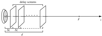
This body-wall is similarly modeled as in [22], however the aberrative effect is here chosen to be more severe in order to test the feasibility of the SURF beam generation methods under harsher imaging conditions. The body-wall model construction method is thoroughly described in [23] and the characteristics of the modeled body-wall, as found from simulations of back-propagation of the signal from an excited point source in focus, are displayed in Table I.
| Amplitude correlation-length | 1.4 mm |
| Amplitude RMS fluctuation | 4.5 dB |
| Time-delay correlation-length | 1.2 mm |
| Time-delay RMS fluctuation | 450 ns |
At zero-pressure, the material property average values are: speed of sound 1550 m/s, density 1.06 mg/mm3, and the nonlinearity parameter . The attenuation is described by a power-law making it proportional to with the loss dB/cm at 1 MHz. Details on the simulation and attenuation implementations are given in Ref. 24.
Both the corresponding non-aberrated SURF beam and the non-aberrated fundamental beam are simulated and used as reference beams. All beams are generated by detection of the temporal maximum of the pressure field at each spatial coordinate.
II-C SURF signal post-processing
Two different signal post-processing methods, further described and analyzed for a homogeneous medium in [2], are applied on the SURF field data filtered around the frequency MHz. They both aim to further suppress the SURF transmit-beam at some depth , so that the ratio between the beam energy within the imaging depth region and the energy at the chosen suppression depth is increased. This way image reverberation-artifacts due to first scattering from some strongly reflecting feature at the depth may be suppressed.
In short, given that the two transmit HF waves propagated in conjunction with LF manipulation pulses of opposite polarities are and , the second HF signal is processed to form the field which is used to form the difference field
| (1) |
The adjusted SURF synthetic transmit-beam is then generated from .
The first post-processing method involves a pure time-shift of the field by so that
| (2) |
The second post-processing method involves some more general filter which makes the on-axis pulse of and equal at the depth :
| (3) |
Here this filter is determined by comparison of the two simulated fields as averaged over a laterally mm wide region on-axis at the depth and finding the filter that makes these two average signals equal. For the demonstrated inhomogeneous medium case, the adjustment filter utilized is not generated from the actual aberrated and fields, but instead from the and emerging from the homogeneous medium propagation. This approach is chosen to in some extent better emulate how an à priori determination of could be performed by experimental field characterization. The averaging over the region , which was not performed in [2], is introduced to take a finite hydrophone width into account. The determination of in a real medical imaging setup may be more cumbersome, as further discussed in [2]. We remark that when receive channel-data is available, any of the proposed suppression methods may be applied, and images can be reconstructed independently for multiple choices of . Great flexibility in reverberation suppression customization is hence enabled.
II-D Compared transmit-beams and fields
In the following is a listing of the simulated datasets utilized to generate the transmit-beams that are compared within this work:
II-D1 Non-adjusted SURF beam
The HF transmit fields and , filtered around MHz on the same actual dataset as utilized in [1], are subtracted without further modification to generate .
II-D2 Time-shift adjusted SURF beams
The time-shift adjustment post-processing method is applied on the same original dataset as used to generate the non-adjusted SURF, for a number of different to generate the adjusted HF field .
II-D3 Filter-adjusted SURF beams
The filter-adjustment post-processing method is applied on same original dataset as for the non-adjusted SURF, for a number of different to generate the adjusted HF field .
II-D4 Fundamental imaging beam
Standard fundamental imaging transmit fields without LF manipulation or SURF processing. The transmit pulse is equal to the HF part of the SURF pulse complex described above.
III Results and Discussion
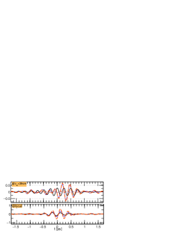
The propagation effects caused by the modeled body-wall, including focus degradation, are further illustrated in Fig 2, which shows beam profiles, transmit-beams, and axial pulses for (non-adjusted) SURF and fundamental beams.
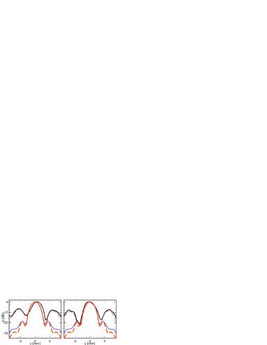


 : fundamental (inhomog.),
 : SURF (inhomog..),
  : fundamental (homog.),
  : SURF (homog.).
 | SURF | ||||
| non- | time-shift | filter | ||
| fundamental | adjusted | adjusted | adjusted | |
| homogeneous | FH | SH | SH | SH |
| inhomogeneous | FI | SI | SI | SI |
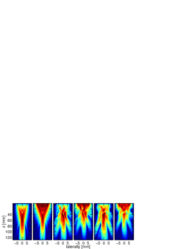
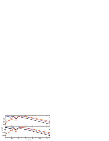
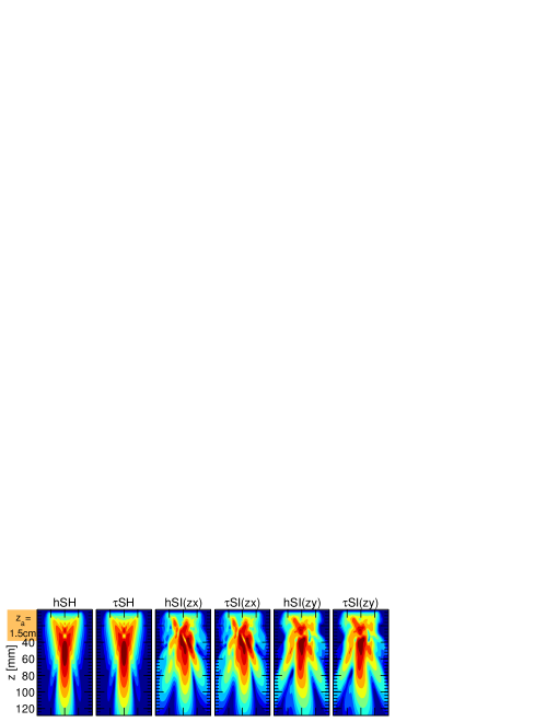
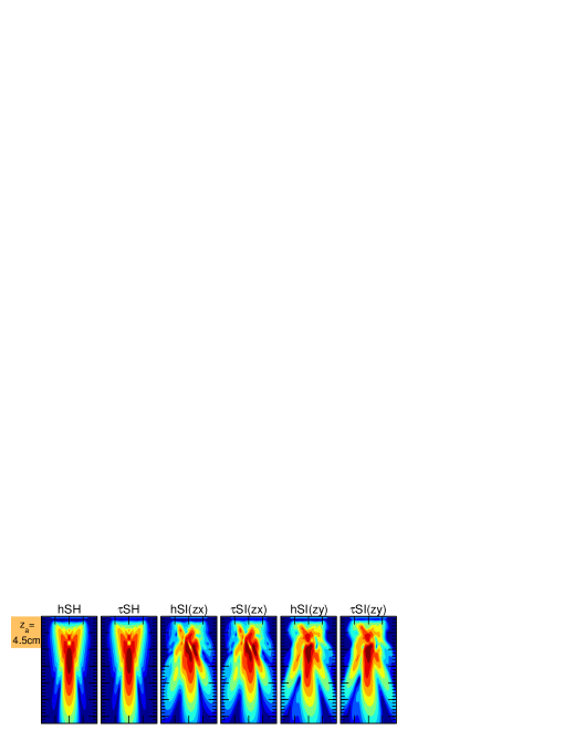
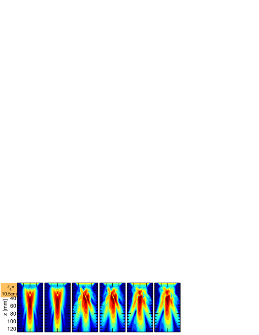
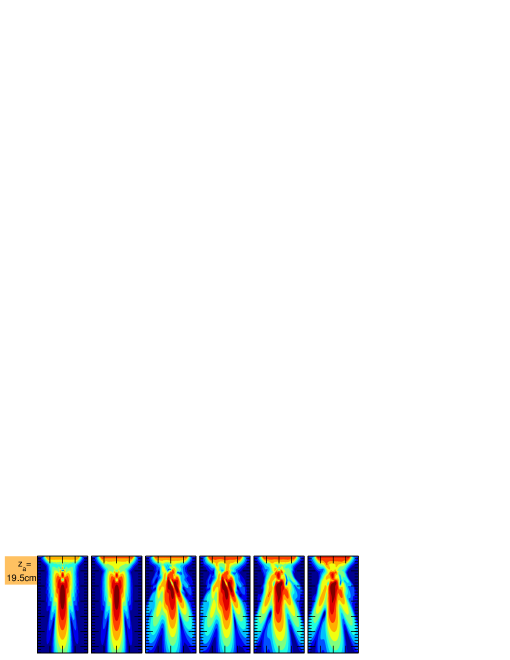
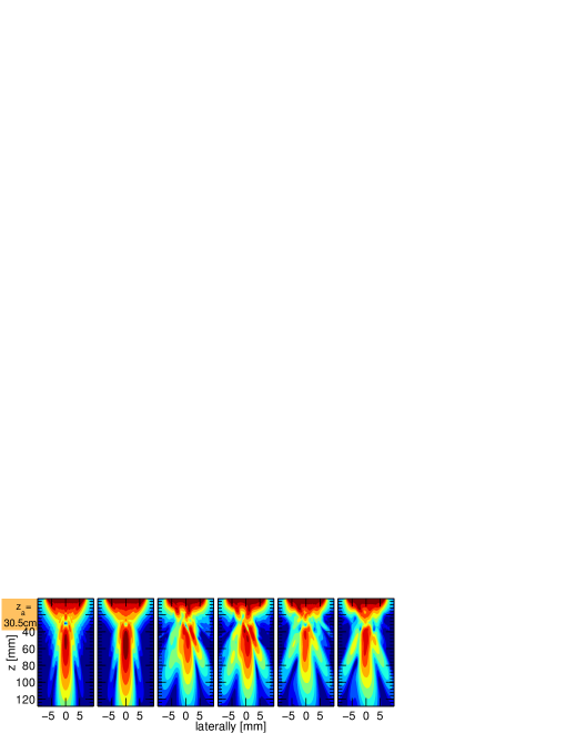
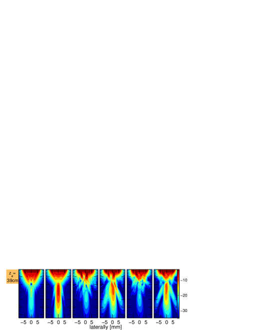
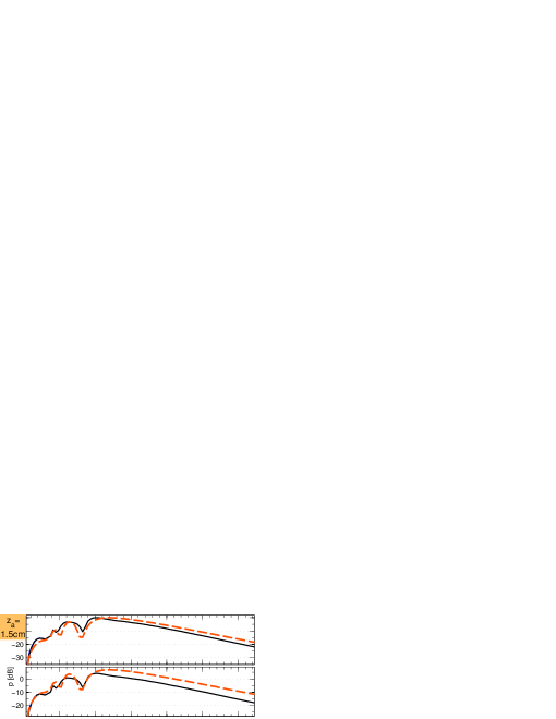
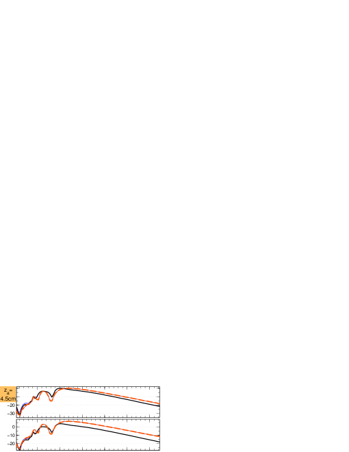
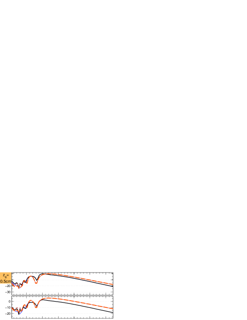
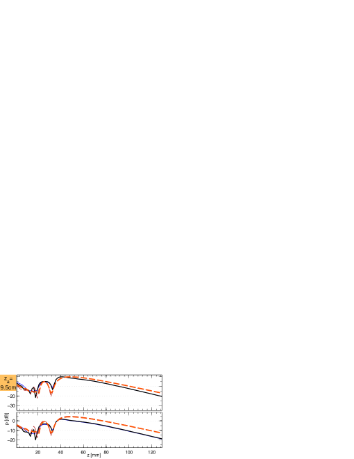
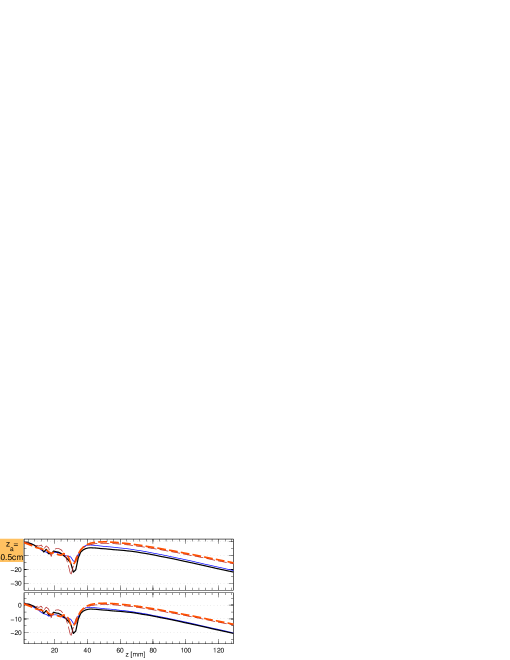
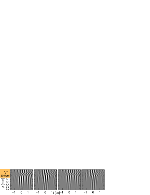
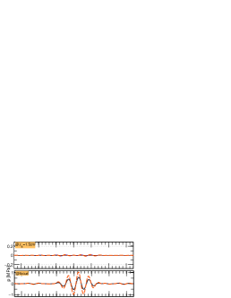
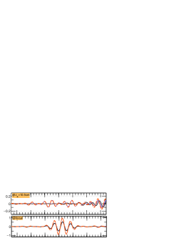
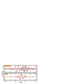
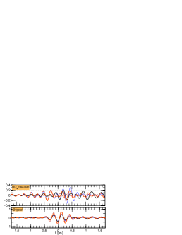
Figure 3 shows adjusted SURF beams simulated by homogeneous and inhomogeneous propagation with 6 different choices of suppression depths , using both time-shift adjustment or filter-adjustment. The corresponding beam profiles along the axis are shown in Fig. 4. The time-development of the SURF on-axis pulses as a function of depth are displayed in 5 for the same set. These pulses are further inspected in Fig. 6, where their signatures at the depths are compared to the signatures in focus. Side-by-side comparison of the adjusted beams for different is of particular significance, as it visualizes that for the selected depths, the adjustment methods are about as viable for inhomogeneous as for homogeneous media.
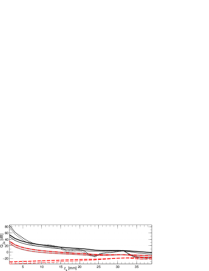
The adjustment abilities in inhomogeneous media are further quantified by the specific reverberation suppression beam quality ratios corresponding to the shown beams. These are displayed for different suppression depths in Fig. 7 using time-shift adjustment and filter-adjustment as well as for non-adjusted and fundamental beams. This is done both for homogeneous medium and for propagation through the body-wall. The figure also shows general reverberation suppression quality ratios for different time-shift adjustments for the same medium cases. The specific quality ratio was defined in [2] as:
| (4) |
where is the beam energy at the spatial coordinate described by the cylindrical coordinates . The imaging depth region is within and is equal to the focal region with the given aperture and imaging frequency. The measure illustrates how well the transmit beam is adapted to suppression of reverberations where the first scattering takes place at the depth . The general quality ratio was defined in [1] as:
| (5) |
The measure illustrates the ability of the transmit beam to suppress reverberations when the first scatterings are distributed within the near-field region . A related quality measure was applied in [25] for assessment of near-field echo suppression in tissue-harmonic imaging.
The body-wall model chosen causes severe aberration disturbance of the transmit fields. Its characteristics, as displayed in Table I., may be compared to values found at body temperature in experimental measurements on human abdomen specimens done by Hinkelman et al. [26], where the amplitude correlation length is within 1.3 to 2.9 mm, the amplitude RMS value within 2.9 to 3.5 dB, the time-delay correlation length within 24 to 64 ns, and the time-delay correlation length within 3.3 to 17 mm. Especially the time-delay RMS fluctuation is more severe for the aberrative model utilized here than for the cited measurements.
The RMS magnitude of the time-delay fluctuations introduced by the utilized aberrating layer model are, as indicated in Table I., ns, while the accumulated time-delay between and needed to generate maximum SURF imaging gain following the model introduced in [1], is smaller: ns. The SURF synthetic transmit-beam is however shown to be generated despite these great delays induced by the body-wall. Two factors explain this:
1) The and propagate following the same path and therefore experience the same aberration time-delay at each spatial point. Therefore this abberation delay is canceled when forming the difference field .
 |
 |
 |
 |
 |
 |
 |
 |
 |
 |
 |

|
 |
 |
 |
 |
 |
 |

 (homogeneous) and
  (inhomogeneous. Filter-adjusted:
  (homog.) and
  (inhomog.), No adjustment:
  (homog.) and
  (inhomog.), Fundamental beam:
  (homog.) and
  (inhomog.).
2) The LF part of each SURF pulse complex experience the same aberration delay during propagation. Therefore the HF pulse remains within roughly the same LF pressure as when propagating without aberration. This is illustrated in Fig. 8, where the total propagating SURF pulse complexes with positive and negative LF polarities are sampled at one depth within the body-wall.
The SURF transmit-beam in the homogeneous medium has suppressed focal sidelobes compared to the fundamental transmit-beam, while the mainlobe stays unchanged. The suppression is only around dB for the first sidelobe, while it increases to around dB for the second sidelobe. In the inhomogeneous medium case, the sidelobes are also suppressed for SURF compared to fundamental, however about half as much as for the homogeneous medium.
Figure 7 indicates that, both for homogeneous and inhomogeneous medium, the time-shift adjustment gives superior, more robust and more predictable specific reverberation suppression quality ratio than the filter-shift adjustment for depths where mm, while the ratio is higher for filter-adjustment for shallower depths. The time-shift adjusted beams have around dB above for the non-adjusted SURF beam, both for homogeneous and inhomogeneous medium.
The ratio calculated in the homogeneous medium for the time-shift adjusted beams, the non-adjusted SURF beams and the fundamental beams align well with what was found for the same 2-D axisymmetric simulations in [2]. The filter-adjusted SURF beams do however show worse and more unstable in the present 3-D simulations than in the referred work. This is due to the averaging over the region which is used here on both and before is calculated. Then the canceling of temporal parts of the pulses which vary the most over the region , that is the edge wave parts of the pulse, are less suppressed. The amplitude of these edge waves may be decreased if apodization is applied to the surface of pulse transmission [27, 28]. That way the lateral region where generates high suppression might get larger.
For mm, is lower both for the homogeneous and inhomogeneous media for time-shift, compared to for filter-adjustment. Therefore use of time-shift is preferred when is far from the transducer. This is also reflected in the cm section of Fig. 3 both with and without the body-wall. There significant in-focus field degradation is observed for the filter-adjustment beam as opposed to for the time-shift adjusted beam.
Ultrasound images of patients whose anatomy cause noisy images, for example due to obesity, are likely to be blurred owing to both aberration and reverberation noise.
The repetitive nature of reverberation noise makes the receive signals correlated both in the temporal and the spatial directions. This may obstruct estimation of the filter that is used in aberration correction schemes like [29]. By suppression of reverberation noise, estimation of the aberration correction filter is thus enhanced, and therefore the aberration correction itself is likely to get more accurate. Instruments that may combine aberration correction with reverberation suppression are thus, compared to instruments with aberration correction alone, likely to produce images of enhanced quality also regarding the wave-front aberration noise.

IV Concluding remarks
This work indicates through computer simulations that generation a SURF reverberation suppression synthetic transmit-beam is feasible in spite of the propagating waves being distorted by an inhomogeneous medium which emulates a strongly aberrating body-wall. Generation of the beam is hence also likely to be possible when utilizing body-wall models producing less severe aberrations corresponding to what was measured e.g. in [26].
The post-processing suppression depth adjustment methods, as previously implemented in [2] for a homogeneous medium, are here shown to be feasible on the simulated aberrated fields also within an inhomogeneous medium.
Further research of interest within the field also includes in vivo imaging through true body-walls using the investigated methods and also performance comparisons with tissue harmonic imaging, especially when utilizing pulse inversion.
Non-adjusted and adjusted beams could also be generated from SURF transmit fields measured by a hydrophone in a water-tank. Beam generation with a inhomogeneous body-wall setup may be emulated using some aberrating material within the tank, e.g as done by use of gel layers in [30]. It is furthermore desirable to perform numerical propagation simulations using a tool that properly handles multiple scattering (as does not the forward-propagation method used here) in order to further quantify the reverberation suppression ability of the methods within an aberrative medium, as well as doing comparisons to the performance of tissue harmonic imaging using the same setup.
We expect the family of SURF reverberation suppression methods to come out as versatile techniques to enhance ultrasound image reconstruction also in clinical settings.
References
- [1] S. P. Näsholm, R. Hansen, S.-E. Måsøy, T. F. Johansen, and B. A. J. Angelsen, “Transmit beams adapted to reverberation noise suppression using dual-frequency SURF imaging,” IEEE Trans. Ultrason. Ferroelectr., Freq. Control, vol. 56, no. 10, pp. 2124–2133, 2009.
- [2] S. P. Näsholm, R. Hansen, and B. A. J. Angelsen, “Post-processing enhancement of reverberation-noise suppression in dual-frequency SURF imaging,” IEEE Trans. Ultrason. Ferroelectr., Freq. Control, vol. 58, no. 2, pp. 338–348, 2011.
- [3] L. M. Hinkelman, T. D. Mast, L. A. Metlay, and R. C. Waag, “The effect of abdominal wall morphology on ultrasonic pulse distortion. Part I: Measurements,” J. Acoust. Soc. Am., vol. 104, no. 6, pp. 3635–3649, 1998.
- [4] C. F. Keogh and P. L. Cooperberg, “Is it real or is it an artifact,” Ultrasound Q., vol. 17, no. 4, pp. 201–210, Dec. 2001.
- [5] K. Mahmutyazicioglu, H. A. Tanriverdi, H. Ozdemir, A. Barut, H. Davsanci, and S. Gundogdu, “Transabdominal pulse inversion harmonic imaging improves assesment of ovarian morphology in virgin patients with pcos: comparison with conventional b-mode sonography,” Eur. J. Radiol., vol. 53, no. 2, pp. 208–286, Feb. 2005.
- [6] K. A. Scanlan, “Sonographic artifacts and their origins,” Am. J. Roentgenol., vol. 156, no. 6, pp. 1267–1272, Jun. 1991.
- [7] A. Shmulewitz, S. A. Teefey, and B. S. Robinson, “Factors affecting image quality and diagnostic efficacy in abdominal sonography: A prospective study of 140 patients,” J. Clin. Ultrasound, vol. 21, no. 9, pp. 623–630, 1993.
- [8] G. F. Pinton, G. E. Trahey, and J. J. Dahl, “Sources of image degradation in fundamental and harmonic ultrasound imaging using nonlinear, full-wave simulations,” IEEE Trans. Ultrason. Ferroelectr., Freq. Control, vol. 58, no. 4, pp. 754–765, Apr. 2011.
- [9] ——, “Erratum: Sources of image degradation in fundamental and harmonic ultrasound imaging: a nonlinear, full-wave, simulation study [Apr. 11 754–765],” IEEE Trans. Ultrason. Ferroelectr., Freq. Control, vol. 58, no. 6, pp. 1272–1283, Jun. 2011.
- [10] B. Angelsen, Ultrasound imaging. Waves, signals and signal processing. Trondheim: Emantec, 2000, vol. II, http://www.ultrasoundbook.com.
- [11] R. Hansen, S.-E. Måsøy, T. A. Tangen, and B. A. Angelsen, “Nonlinear propagation delay and pulse distortion resulting from dual frequency band transmit pulse complexes,” J. Acoust. Soc. Am., vol. 129, no. 2, pp. 1117–1127, 2011.
- [12] S.-E. Måsøy, Ø. Standal, J. M. Deibele, S. P. Näsholm, B. Angelsen, T. F. Johansen, T. A. Tangen, and R. Hansen, “Nonlinear propagation acoustics of dual–frequency wide–band excitation pulses in a focused ultrasound system,” J. Acoust. Soc. Am., vol. 128, no. 5, pp. 2695–2703, 2010.
- [13] R. Hansen, S.-E. Måsøy, T. F. Johansen, and B. A. Angelsen, “Utilizing dual frequency band transmit pulse complexes in medical ultrasound imaging,” J. Acoust. Soc. Am., vol. 127, no. 1, pp. 579–587, 2010.
- [14] C. X. Deng, F. L. Lizzi, A. Kalisz, A. Rosado, R. H. Silverman, and D. J. Coleman, “Study of ultrasonic contrast agents using a dual-frequency band technique,” Ultrasound Med. Biol., vol. 26, pp. 819–831, 2000.
- [15] B. A. J. Angelsen and R. Hansen, “SURF imaging – a new method for ultrasound contrast agent imaging,” in Proc. IEEE Ultrason. Symp., New York, NY, Oct. 2007, pp. 531–541.
- [16] A. Bouakaz, M. Versluis, J. Borsboom, and N. de Jong, “Radial modulation of microbubbles for ultrasound contrast imaging,” IEEE Trans. Ultrason. Ferroelectr., Freq. Control, vol. 54, no. 11, pp. 2283–2290, Nov. 2007.
- [17] S.-E. Måsøy, Ø. Standal, P. Näsholm, T. F. Johansen, R. Hansen, and B. Angelsen, “SURF imaging: In vivo demonstration of an ultrasound contrast agent detection technique,” IEEE Trans. Ultrason. Ferroelectr., Freq. Control, vol. 55, no. 5, pp. 1112–1121, 2008.
- [18] R. Hansen and B. A. J. Angelsen, “SURF imaging for contrast agent detection,” IEEE Trans. Ultrason. Ferroelectr., Freq. Control, vol. 56, no. 2, pp. 280–290, 2009.
- [19] M. Emmer, H. J. Vos, M. Versluis, and N. D. Jong, “Radial modulation of single microbubbles,” IEEE Trans. Ultrason. Ferroelectr., Freq. Control, vol. 56, no. 11, pp. 2370–2379, 2009.
- [20] M. Frijlink, H. Kaupang, T. Varslot, and S.-E. Masoy, “Abersim: A simulation program for 3D nonlinear acoustic wave propagation for arbitrary pulses and arbitrary transducer geometries,” in IEEE Ultrasonics Symp. Proc., Nov. 2008, pp. 1282–1285.
- [21] T. Varslot and G. Taraldsen, “Computer simulation of forward wave propagation in soft tissue,” IEEE Trans. Ultrason. Ferroelectr., Freq. Control, vol. 52, no. 9, pp. 1473–1482, 2005.
- [22] T. Varslot, S.-E. Måsøy, T. F. Johansen, and B. Angelsen, “Aberration in nonlinear acoustic wave propagation,” IEEE Trans. Ultrason. Ferroelectr., Freq. Control, vol. 54, no. 3, pp. 470–479, Mar. 2007.
- [23] S.-E. Måsøy, T. F. Johansen, and B. Angelsen, “Correction of ultrasonic wave aberration with a time delay and amplitude filter,” J. Acoust. Soc. Am., vol. 113, no. 4, pp. 2009–2020, Apr. 2003.
- [24] H. Kaupang, “Abersim 2.x reference manual with tutorials,” Norwegian University of Science and Technology, Trondheim, Norway, Tech. Rep., 2008.
- [25] H. Høilund-Kaupang and S.-E. Måsøy, “Transmit beamforming for optimal second-harmonic generation,” IEEE Trans. Ultrason. Ferroelectr., Freq. Control, vol. 58, no. 8, pp. 1559–1569, Aug. 2011.
- [26] L. M. Hinkelman, D.-L. Liu, L. A. Metlay, and R. C. Waag, “Measurements of ultrasonic pulse arrival time and energy level variations produced by propagation through abdominal wall,” J. Acoust. Soc. Am., vol. 95, no. 1, pp. 530–541, 1994.
- [27] G. R. Harris, “Transient field of a baffled planar piston having an arbitrary vibration amplitude distribution ,” J. Acoust. Soc. Am., vol. 70, pp. 186–204, Jul. 1981.
- [28] M. Tabei, T. D. Mast, and R. C. Waag, “Simulation of ultrasonic focus aberration and correction through human tissue,” J. Acoust. Soc. Am., vol. 113, no. 2, pp. 1166–1176, 2003.
- [29] S.-E. Måsøy, T. Varslot, and B. Angelsen, “Iteration of transmit-beam aberration correction in medical ultrasound imaging,” J. Acoust. Soc. Am., vol. 117, no. 1, pp. 450–461, 2005.
- [30] Y. Jing and R. O. Cleveland, “Modeling the propagation of nonlinear three-dimensional acoustic beams in inhomogeneous media,” J. Acoust. Soc. Am., vol. 122, no. 3, pp. 1352–1364, 2007.
![[Uncaptioned image]](/html/1303.6077/assets/x66.png) |
Sven Peter Näsholm was born in Örnsköldsvik, Sweden, in 1975. He received his M.Sc. degree in engineering physics in 2002 from Umeå University, Sweden. In 2008, he successfully defended his Ph.D. thesis entitled “Ultrasound beams for enhanced image quality” at the Norwegian University of Science and Technology, Trondheim, Norway. In 2009, he joined the Digital Signal Processing and Image Analysis group as a pos-doctoral fellow at the Department of Informatics, University of Oslo, Norway. His research interests are within the fields of sonar and ultrasound imaging including nonlinear effects, transducer design, field simulation, and acoustic noise suppression. |
![[Uncaptioned image]](/html/1303.6077/assets/x67.png) |
Bjørn A. J. Angelsen was born 1946 in Vestvågøy, Norway. He received a MEE in 1971 from the Norwegian University of Science and Technology, Trondheim, and a Ph.D. from the same University in 1977. His Ph.D. work was on Doppler ultrasound measurement of blood velocities and flow in the heart and the large arteries. He is a professor of Medical Imaging at the same university since 1983. In 1977–78 he was a visiting Post Doc at University of California, Berkeley, and Stanford Research Institute, Palo Alto. He has been strongly involved in development of cardiac ultrasound imaging instruments in collaboration with Vingmed Ultrasound, now GE Vingmed Ultrasound. He has written textbooks on ultrasound cardiac Doppler measurements and theoretical ultrasound acoustics, and holds several patents in the field of ultrasound imaging. |