Storage of electromagnetic waves in a metamaterial that mimics electromagnetically induced transparency
Abstract
We propose a method for dynamically controlling the properties of a metamaterial that mimics electromagnetically induced transparency (EIT) by introducing varactor diodes to manipulate the structural symmetry of the metamaterial. Dynamic modulation of the EIT property enables the storage and retrieval of electromagnetic waves. We confirmed that the electromagnetic waves were stored and released, while maintaining the phase distribution in the propagating direction.
pacs:
41.20.Jb, 78.67.Pt, 42.50.GyThe group velocity of electromagnetic waves, which represents the propagation speed of the pulse envelope, can be modified in dispersive media. Electromagnetically induced transparency (EIT), which realizes highly dispersive media and leads to a slower light propagation speed, was originally investigated in atomic physics. Harris (1997); Fleischhauer and Marangos (2005) The EIT effect enables the propagation of light through an initially opaque medium by the incidence of auxiliary light, which is called control light. Furthermore, the group velocity of the light is dramatically decreased in the transparent region. Hau et al. (1999) Studies of the slowing of light using EIT phenomena have developed the storage of optical pulses. Fleischhauer and Lukin (2000) The storage of light can be realized by dynamically reducing the group velocity when the light pulse is trapped in an EIT medium. The storage of light using EIT is a promising technology, which leads to the realization of optical memory and quantum memory. Phillips et al. (2001); Liu et al. (2001); Turukhin et al. (2002)
EIT effects are not unique to atomic systems. Similar effects have been observed in various systems, such as optical waveguides equipped with cavities Little et al. (1999); Xu et al. (2006); Totsuka et al. (2007); Kekatpure et al. (2010) and circuit models. Garrido Alzar et al. (2002); Nakanishi et al. (2005) In recent years, the implementation of EIT effects in metamaterials has attracted considerable attention. The metamaterial is an assembly of subwavelength structures, which are designed to realize unconventional electromagnetic properties. It is possible to design metamaterials that mimic EIT effects, and these metamaterials are sometimes referred to as EIT metamaterials. Zhang et al. (2008); Tassin et al. (2009); Luk’yanchuk et al. (2010) Each element in an EIT metamaterial has two resonant modes, one of which is a highly radiative mode coupled to propagating waves, which has a low quality factor. The other is a “trapped mode” with a high quality factor, which is excited only through coupling with the radiative mode, not by the propagating waves directly. If the resonant frequency of the trapped mode is tuned to around that of the radiative mode, and if the incident waves are oscillating at , the energy excited in the radiative mode is transferred to the trapped mode with low-energy dissipation. As a consequence, a suppression of the dissipation in the metamaterial, or the EIT effect, is observed. The physical origin of the transparency in the metamaterial differs from that of an EIT medium composed of three-level atoms with two ground states and a common excited state, but there are good correspondences between the two systems. The coherent oscillation between a ground state and the excited state in an atomic EIT system corresponds to the resonance in the radiative mode in EIT metamaterial, and the coherent oscillation between two ground levels with long relaxation time corresponds to the resonance in the trapped mode. EIT metamaterials can be implemented in various frequency regions by applying the same design rules, and a variety of EIT metamaterials have been demonstrated in the microwave, Fedotov et al. (2007); Papasimakis et al. (2008); Kurter et al. (2011); Kang et al. (2011) terahertz, Chiam et al. (2009); Li et al. (2011); Singh et al. (2011); Liu et al. (2012) and optical regions. Liu et al. (2009); Zhang et al. (2010); Huang et al. (2011) In addition to the slow propagation of electromagnetic waves, applications for accurate sensing Dong et al. (2010) and manipulation of the near field Zhang et al. (2012) have also been investigated by taking advantage of the sharp resonance.
The storage of electromagnetic waves is one of the most fascinating applications of the EIT effect. To achieve this storage, the coupling between the trapped mode and the radiative mode must be dynamically controlled. In most EIT metamaterials, control of the coupling has been realized by mechanically tuning the relative positions of two resonators, and dynamic control is difficult. Some researchers have succeeded in the semi-static control of EIT properties by changing the incident angles Tamayama et al. (2012); Jin et al. (2012) or by structural modification induced by carrier excitation in a semiconductor. Gu et al. (2012) However, the storage and retrieval of electromagnetic waves has not been reported. The main goal of this Rapid Communication is to realize the storage and retrieval of electromagnetic waves in a metamaterial. Extending the idea of EIT metamaterials with broken structural symmetry, Fedotov et al. (2007); Kang et al. (2011); Singh et al. (2011) we propose an EIT metamaterial with variable capacitors (varactors) installed to dynamically control the structural symmetry, which determines the coupling between two resonant modes. We first describe the design and operating principles of the metamaterial, while discussing simulation results. We also show experimental results demonstrating semi-static control of the EIT properties of the metamaterial in the microwave region. In the latter part of this Rapid Communication, we experimentally demonstrate the storage and retrieval of electromagnetic waves, employing dynamic modulation of the EIT properties. We also confirm that the waves are stored and released while maintaining the phase distribution in the propagating direction.
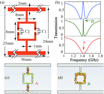
Figure 1(a) shows a unit cell of our metamaterial, which is made of metal. Two variable capacitors, and , are introduced at two gaps in the center loop to dynamically control the EIT properties. We calculate the transmission properties of the metamaterial using an electromagnetic simulator (cst mw studio) for various pairs of values for and . In the simulation, periodic boundary conditions are set for the unit cell with a size of to simulate an infinite array of the unit structures. The incident waves are vertically polarized. The results are shown in Fig. 1(b) for (bottom), (middle), and (top). For , the transmission is depressed over a broad spectrum. At the center of the depression, a resonant current is induced on the metal, as shown in Fig. 1(c). This mode can be regarded as a radiative mode. On the other hand, for , sharp transparent regions appear in the broad resonant line. At the transmission peak, a resonant loop current is induced, as shown in Fig. 1(d), and this can be regarded as a trapped mode, which has a much higher quality factor than the radiative mode and is uncoupled from incident wave. (The structure is designed so that the resonant frequencies of the two modes coincide.) The electromagnetic energy received in the radiative mode is transferred into the trapped mode through a coupling, which is provided by breaking the symmetry of the metamaterial. As a result, dissipation is suppressed and the metamaterial is rendered transparent. The increase in the degree of asymmetry results in the broadening of the transparent window, as is clearly shown in the middle and top panels of Fig. 1(b). It is possible to control the width of the transparent window without changing the center of the window. This is accomplished by keeping the composite capacitance in the loop, , constant. The minimum of is limited by the linewidth of an isolated trapped mode, which is determined by the radiation loss of the loop current and Ohmic loss in the capacitors. The transparency peak is deteriorated by the loss in the trapped mode.
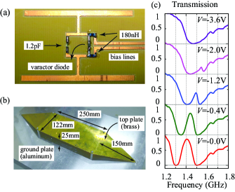
To experimentally demonstrate the EIT effects in the microwave region, we fabricated the proposed structures using a copper film on a dielectric substrate with a permittivity of 3.3 and a thickness of , as shown in Fig. 2(a). In one side of the loop, we introduced a varactor diode (Infineon BBY52-02W), whose capacitance is a function of the applied bias voltage . The bias voltage was fed through - inductors, which were introduced to pass only the bias voltage and to isolate the structure from the bias circuitry for signals at the operating frequency of the metamaterial of over . Ohmic loss in the varactor diode, which is not negligible, degrades the quality factor of the trapped mode. Therefore, we used a normal capacitor () with low Ohmic loss at the other side. In this situation, unlike a simulation in which is kept constant, the center and width of the transparent window are expected to change with . For measurements, we introduced a stripline waveguide with tapered structures, as shown in Fig. 2(b) (see details in Ref. Nakanishi et al., 2012). Three layers of the metamaterial, each of which contained a single structure, were prepared. We placed these layers in the waveguide with a separation of , which was sufficient to avoid undesired coupling between the layers, and measured the transmission through the metamaterial. The results of these transmission measurements for various are shown in Fig. 2(c). For , a broad depression in the transmission is observed. This indicates that the elements of the metamaterial are symmetric, i.e., , which agrees with the value in the varactor diode data sheet. By breaking the symmetry, we can observe transparent windows. When increasing by reducing , the asymmetry of the structure is enhanced, and the transparent window becomes wider. The transmission peaks shift to a lower frequency because they correspond to the resonant frequencies of the trapped modes, which are determined by the loop capacitance .
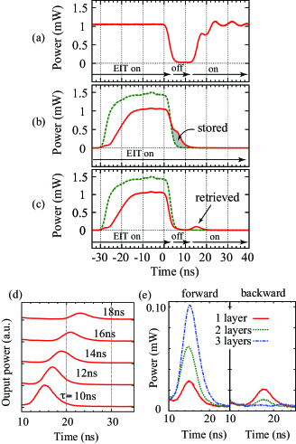
Next, we demonstrate the modulation of continuous waves by varying with time to confirm the dynamic control of the EIT effect and to identify the timing and transient time of the modulation. By using a pulse generator, we apply negative rectangular pulses with an amplitude of , an offset of , and a width of , at the same time for all of the varactors. With this setting, the transmission property of the metamaterial switches from the second lowest spectrum () to the top spectrum () in Fig. 2(c). A signal generator feeds continuous waves at , which corresponds to the transmission peak for , into the waveguide containing the three-layered metamaterial. We record the power of the waves transmitted through the waveguide. Figure 3(a) shows transmitted microwave power under the modulation of the metamaterial. The origin for time is set to the moment when the signal starts to decrease. For , the bias is , and the incident waves can travel through the metamaterial because of the EIT effect. After some transient time of around from , almost all of the energy is blocked by the metamaterial, because the EIT effect disappears for . At , where is the transient time for a transparent window to emerge through the discharge of the varactor diode, the transmission starts to recover. In Fig. 3(a), the state denoted “EIT on” (“EIT off”) corresponds to the state in which the trapped mode and the radiative mode are coupled (decoupled).
The dynamic switching between EIT on and EIT off states enables the storage of electromagnetic waves by the following procedure. First, the metamaterial is prepared in an EIT on state, in which the radiative and trapped modes are coupled. If the spectrum of the incident pulse is in the transparent window, the pulse transmits through the metamaterial with the transit time or group delay. The delay corresponds to the time period when the electromagnetic energy received in the radiative mode is transferred into the trapped mode and returns to the radiative mode through coupling. If during the propagation the metamaterial is changed into an EIT off state, where the two resonant modes are decoupled, some of the energy is captured in the trapped mode. Then, this energy is released by returning the metamaterial to an EIT on state to reintroduce the coupling.
Before the demonstration of pulse storage, we measured the transmission of a pulse through the metamaterial in an EIT on state to estimate the delay of the pulse due to slow propagation in the metamaterial. We prepared a - pulse with a carrier frequency of . The dotted line and the solid line in Fig. 3(b) represent the power of the pulse transmitted through the waveguide without and with the metamaterial, respectively, for . Compared with the original pulse, a fraction of the transmitted pulse is delayed by to , which corresponds to the transit time for some components of the input pulse within the transparent window. (The component outside of the transparent window is blocked by the metamaterial.) In other words, the power in the gray region is temporally stored in the trapped modes. The energy in the gray region can be captured in the trapped modes by switching the metamaterial from the EIT on state to the EIT off state when the input pulse is turned off.
To demonstrate the storage and retrieval of electromagnetic waves, we modulate the bias voltage with a width of , as shown in Fig. 3(a) for an input microwave pulse represented by the dotted line in Fig. 3(b), which is redisplayed as a dotted line in Fig. 3(c). In order to hold the energy corresponding to the gray region in Fig. 3(b), we adjust the timing so that the original pulse is turned off at . Figure 3(c) shows the transmitted power as a solid line. In comparison with the unmodulated case shown in Fig. 3(b), the delayed component (the gray region) is not observed because the energy is stored in the trapped modes, which are decoupled from the radiative modes in the EIT off state. The stored energy starts to be radiated from the radiative mode, when the coupling between the trapped modes and the radiative modes is restored and the transparent window begins to open. By comparing the height of the retrieved pulse at with the height of the original pulse, the efficiency of retrieval is estimated to be about 10%. Figure 3(d) shows the magnified waveforms of retrieved pulses for various . The magnitudes of the retrieved pulses are reduced with increasing , because the stored energy decays in the trapped mode during the EIT off state. The height of the retrieved pulses decays exponentially with a time constant of , which corresponds to the lifetime of the trapped mode.
We compare retrieved pulses propagating in the backward and forward directions for -layered metamaterials () by measuring the waveforms of the reflected and transmitted waves. Figure 3(e) shows retrieved pulses for forward (backward) waves on the left (right) side. For , we observe almost the same amplitudes of retrieved signals propagating in opposite directions because the energy is radiated from a single emitter. With increasing , the retrieved pulses become stronger for forward propagation but diminish for backward propagation. This indicates that the oscillation in each trapped mode during the storage process “inherits” the relative phase of the oscillating electric field of the incident waves at each location, and the retrieved pulse reproduces the phase distributions of the incident waves.
In this Rapid Communication, we have presented a method of dynamically modulating the properties of a varactor-loaded EIT metamaterial, whose characteristics can be controlled by an external voltage source. We have achieved the storage and retrieval of electromagnetic waves. In our experiment, even though we used only three elements of the metamaterial to avoid technical problems such as transmission reduction caused by Ohmic loss in the varactor diodes, we still retrieved 10% of the original pulse height after a storage time of . Decay in the trapped mode, which limits the storage time, could be compensated for by introducing an amplification process. Dong et al. (2010)
We introduced a varactor diode on one side of the element, and the resonant frequency of the trapped mode varied, depending on the bias voltage. Therefore, the oscillation frequency of the trapped mode during the storage period was different from that of the incident waves. The retrieved pulse is frequency chirped because energy is released from the frequency-shifting trapped mode through the radiative mode during the transition time . In order to avoid this frequency chirp, we must reduce by improving the bias circuitry or change both capacitances simultaneously, as was done in the simulation.
We have also shown that the traveling pulses can be stored and recovered without losing their phase information. These results suggest that if we increase the number of layers, we could potentially store the whole of an input pulse with arbitrary temporal shape. It is also possible to store waves with arbitrary transverse modes and any polarizations by appropriately distributing the elements. We believe that the present approach can be applied even to optical regions by replacing the varactor diodes by other nonlinear elements such as a nonlinear optical crystal substrate, whose refractive index can be changed by auxiliary light.
The present research was supported by Grants-in-Aid for Scientific Research No. 22109004 and No. 22560041.
References
- Harris (1997) S. Harris, Phys. Today 50 (7), 36 (1997).
- Fleischhauer and Marangos (2005) M. Fleischhauer, A. Imamoglu and J. P. Marangos, Rev. Mod. Phys. 77, 633 (2005).
- Hau et al. (1999) L. V. Hau, S. E. Harris, Z. Dutton, and C. H. Behroozi, Nature (London) 397, 594 (1999).
- Fleischhauer and Lukin (2000) M. Fleischhauer and M. D. Lukin, Phys. Rev. Lett. 84, 5094 (2000).
- Phillips et al. (2001) D. F. Phillips, A. Fleischhauer, A. Mair, R. L. Walsworth, and M. D. Lukin, Phys. Rev. Lett. 86, 783 (2001).
- Liu et al. (2001) C. Liu, Z. Dutton, C. H. Behroozi, and L. V. Hau, Nature (London) 409, 490 (2001).
- Turukhin et al. (2002) A. V. Turukhin, V. S. Sudarshanam, M. S. Shahriar, J. A. Musser, B. S. Ham, and P. R. Hemmer, Phys. Rev. Lett. 88, 023602 (2001).
- Little et al. (1999) S. T. Chu, B. E. Little, W. Pan, T. Kaneko, and Y. Kokubun, IEEE Photon. Technol. Lett. 11, 1426 (1999).
- Xu et al. (2006) Q. Xu, S. Sandhu, M. L. Povinelli, J. Shakya, S. Fan, and M. Lipson, Phys. Rev. Lett. 96, 123901 (2006).
- Totsuka et al. (2007) K. Totsuka, N. Kobayashi, and M. Tomita, Phys. Rev. Lett. 98, 213904 (2007).
- Kekatpure et al. (2010) R. D. Kekatpure, E. S. Barnard, W. Cai, and M. L. Brongersma, Phys. Rev. Lett. 104, 243902 (2010).
- Garrido Alzar et al. (2002) C. L. Garrido Alzar, M. A. G. Martinez, and P. Nussenzveig, Am. J. Phys. 70, 37 (2002).
- Nakanishi et al. (2005) T. Nakanishi, K. Sugiyama, and M. Kitano, Am. J. Phys. 73, 323 (2005).
- Zhang et al. (2008) S. Zhang, D. A. Genov, Y. Wang, M. Liu, and X. Zhang, Phys. Rev. Lett. 101, 047401 (2008).
- Tassin et al. (2009) P. Tassin, L. Zhang, T. Koschny, E. N. Economou, and C. M. Soukoulis, Phys. Rev. Lett. 102, 053901 (2009).
- Luk’yanchuk et al. (2010) B. Luk’yanchuk, N. I. Zheludev, S. A. Maier, N. J. Halas, P. Nordlander, H. Giessen, and C. T. Chong, Nat. Mater. 9, 707 (2010).
- Fedotov et al. (2007) V. A. Fedotov, M. Rose, S. L. Prosvirnin, N. Papasimakis, and N. I. Zheludev, Phys. Rev. Lett. 99, 147401 (2007).
- Papasimakis et al. (2008) N. Papasimakis, V. A. Fedotov, N. I. Zheludev, and S. L. Prosvirnin, Phys. Rev. Lett. 101, 253903 (2008).
- Kurter et al. (2011) C. Kurter, P. Tassin, L. Zhang, T. Koschny, A. P. Zhuravel, A. V. Ustinov, S. M. Anlage, and C. M. Soukoulis, Phys. Rev. Lett. 107, 043901 (2011).
- Kang et al. (2011) M. Kang, H.-X. Cui, Y. Li, B. Gu, J. Chen, and H.-T. Wang, J. Appl. Phys. 109, 014901 (2011).
- Chiam et al. (2009) S.-Y. Chiam, R. Singh, C. Rockstuhl, F. Lederer, W. Zhang, and A. A. Bettiol, Phys. Rev. B 80, 153103 (2009).
- Li et al. (2011) Z. Li, Y. Ma, R. Huang, R. Singh, J. Gu, J. Han, and W. Zhang, Opt. Express 19, 8912 (2011).
- Singh et al. (2011) R. Singh, I. A. I. Al-Naib, Y. Yang, D. Roy Chowdhury, W. Cao, C. Rockstuhl, T. Ozaki, R. Morandotti, and W. Zhang, Appl. Phys. Lett. 99, 201107 (2011).
- Liu et al. (2012) X. Liu, J. Gu, R. Singh, Y. Ma, J. Zhu, Z. Tian, M. He, J. Han, and W. Zhang, Appl. Phys. Lett. 100, 131101 (2012).
- Liu et al. (2009) N. Liu, L. Langguth, T. Weiss, J. Kästel, M. Fleischhauer, T. Pfau, and H. Giessen, Nat. Mater. 8, 758 (2009).
- Zhang et al. (2010) J. Zhang, S. Xiao, C. Jeppesen, A. Kristensen, and N. A. Mortensen, Opt. Express 18, 17187 (2010).
- Huang et al. (2011) W. Huang, Q. Wang, X. Yin, C. Huang, H. Huang, Y. Wang, and Y. Zhu, J. Appl. Phys. 109, 114310 (2011).
- Dong et al. (2010) Z.-G. Dong, H. Liu, J.-X. Cao, T. Li, S.-M. Wang, S.-N. Zhu, and X. Zhang, Appl. Phys. Lett. 97, 114101 (2010).
- Zhang et al. (2012) S. Zhang, Z. Ye, Y. Wang, Y. Park, G. Bartal, M. Mrejen, X. Yin, and X. Zhang, Phys. Rev. Lett. 109, 193902 (2012).
- Tamayama et al. (2012) Y. Tamayama, T. Nakanishi, and M. Kitano, Phys. Rev. B 85, 073102 (2012).
- Jin et al. (2012) X.-R. Jin, Y. Lu, J. Park, H. Zheng, F. Gao, Y. Lee, J. Yull Rhee, K. Won Kim, H. Cheong, and W. H. Jang, J. Appl. Phys. 111, 073101 (2012).
- Gu et al. (2012) J. Gu, R. Singh, X. Liu, X. Zhang, Y. Ma, S. Zhang, S. A. Maier, Z. Tian, A. K. Azad, H.-T. Chen, A. J. Taylor, J. Han, and W. Zhang, Nat. Commun. 3, 1151 (2012).
- Nakanishi et al. (2012) T. Nakanishi, Y. Tamayama, and M. Kitano, Appl. Phys. Lett. 100, 044103 (2012).