Orientational “Kerr effect” and phase modulation of light in deformed-helix ferroelectric liquid crystals with subwavelength pitch
Abstract
We study both theoretically and experimentally the electro-optical properties of vertically aligned deformed helix ferroelectric liquid crystals (VADHFLC) with subwavelength pitch that are governed by the electrically induced optical biaxiality of the smectic helical structure. The key theoretical result is that the principal refractive indices of homogenized VADHFLC cells exhibit the quadratic nonlinearity and such behavior might be interpreted as the orientational “Kerr effect” caused by the electric-field-induced orientational distortions of the FLC helix. In our experiments, it has been observed that, for sufficiently weak electric fields, the magnitude of biaxiality is proportional to the square of electric field in good agreement with our theoretical results for the effective dielectric tensor of VADHFLCs. Under certain conditions, the 2 phase modulation of light, which is caused by one of the induced refractive indices, is observed without changes in ellipticity of incident light.
pacs:
61.30.Gd, 77.84.Nh, 78.20.Jq, 42.79.Kr , 42.70.DfI Introduction
Nowadays, high-speed, low power consuming phase modulation is in high demand for various applications such as displays, tunable gratings, beam steering and several other photonic devices Engström et al. (2009); Ren et al. (2005); Martínes et al. (2009); Hisakado et al. (2005). Liquid crystal (LC) phase modulators are very popular for this purpose and among all LC phases, nematics are widely used. However, nematics are known to have slow response time and, in addition, this slow response gets worse if the LC layer thickness increases in order to obtain a phase modulation. Therefore, many efforts are in progress to optimize the various LC electro-optical modes for the high speed phase modulations. To improve the response time, some recent work on faster switching LC modes has included polymer stabilized “blue phase” (PSBPLC) mode and chiral nanostructured devices based on Kerr effect Ren et al. (2005); Hasebo et al. (2005); Hisakado et al. (2005); Yan et al. (2010); Cheng et al. (2011); Yan et al. (2013); Zhu et al. (2013).
The Kerr constant for the PSBPLC is generally smaller as compared with other tunable LC phase modulators Ren et al. (2005); Hisakado et al. (2005). So, this mode is characterized by a relatively small phase change. There is, however, the new class of PSBPLS recently reported in Refs. Yan et al. (2010); Cheng et al. (2011); Yan et al. (2013); Zhu et al. (2013) that reveals higher values of the Kerr constant. For these materials, the fabrication procedure is very complicated as it requires special processing condition such as ultraviolet curing at a precise temperature within the LC blue phase or isotropic phase, and the mixture of several components Yan et al. (2010); Cheng et al. (2011); Yan et al. (2013).
Ferroelectric liquid crystals (FLCs) representing another and most promising candidate are characterized by very fast response time. However, most of the FLC modes are not suitable for pure phase modulation devices because their optical axis sweeps in the plane of the cell substrate producing changes in the polarization state of the incident light. In order to get around the optical axis switching problem the system consisting of a FLC half-wave plate sandwiched between two quarter-wave plates was suggested in Ref. Love and Bhandari (1994). But, in this system, the phase modulation requires the smectic tilt angle to be equal to 45 degrees. This value is a real challenge for the material science. Even though some of the antiferroelectric and ferroelectric liquid crystals possess the desired tilt angle, the difficulty is that the response time dramatically increases when the tilt angle grows up to 45 degrees Barnik et al. (1987); Pozhidaev et al. (1988).
In this article, we deal with the approach to phase modulation that uses the electro-optical properties of helical structures in deformed helix ferroelectric liquid crystals (DHFLC) Beresnev et al. (1989); Chigrinov (1999); Lee et al. (2005); Kiselev et al. (2011). Our goal is to systematically examine the physical characteristics that govern phase modulation in vertically aligned DHFLC (VADHFLC) cells where the twisting axis of FLC helix is normal to the substrates and the helix pitch, , is short as compared to the wavelength of light, .
The paper is organized as follows.
In Sec. II, we begin with the theoretical analysis which is based on a generalized version of the theory developed in Ref. Kiselev et al. (2011). For the effective dielectric tensor of homogenized VADHFLCs with the subwavelength pitch, it turned out that, in agreement with the results of the experimental study Lee et al. (2005) where the VADHFLC mode was used to achieve the phase modulation at the wavelength 1.55 m, in-plane rotations of the optical axes are suppressed. Optical anisotropy of short-pitch VADHFLCs is found to be generally biaxial and, in the low voltage regime, the electric field dependence of the refractive indices exhibits the quadratic nonlinearity that can be interpreted as the orientational “Kerr effect”.
Electro-optical properties of VADHFLC cells with the subwavelength helix pich are studied experimentally in Sec. III. Experimental details are given in Sec. III.1, where we describe the samples and the setup employed to perform measurements. The experimental results verifying the theoretical predictions are presented in Sec. III.2.
Finally, in Sec. IV, we draw the results together and make some concluding remarks.
II Theory
Optical properties of planar aligned DHFLC cells with subwavelength pitch, where the axis of FLC helix, , is parallel to the substrates, was described in terms of the effective dielectric tensor of homogenized FLC helical structure in Ref. Kiselev et al. (2011). The general result of Ref. Kiselev et al. (2011) is that under the action of the electric field applied along the normal to the twisting axis, , a DHFLC cell, in which the zero-field optical anisotropy is uniaxial with the optical axis parallel to the helical axis , becomes biaxially anisotropic with the principal optical axes rotated about the vector of applied electric field, .
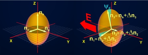
In this section our task is to show that similar behaviour applies to the case of the slab geometry of vertically aligned DHFLC cells which is depicted in Fig. 1. For this geometry, the above effect is illustrated in Fig. 2.
To this end, we introduce the effective dielectric tensor, , describing a homogenized DHFLC helical structure characterized by the director
| (1) |
where is the -director, that lies on the smectic cone with the smectic tilt angle and rotates in a helical fashion about a uniform twisting axis forming the FLC helix with the subwavelength pitch, . The polarization unit vector
| (2) |
is directed along the vector of spontaneous ferroelectric polarization, , and, for a vertically aligned FLC helix in the slab geometry shown in Fig. 1, we have
| (3) |
where is the azimuthal angle around the cone
| (4) |
that depends on the applied electric field, , through the electric field parameter linearly proportional to the ratio of the applied and critical electric fields Chigrinov (1999); Hedge et al. (2008): .
For a biaxial FLC, the components of the dielectric tensor, , are given by
| (5) |
where and are the anisotropy parameters. Note that, in the case of uniaxial anisotropy with , the principal values of the dielectric tensor are: and , where () is the ordinary (extraordinary) refractive index and is the magnetic permittivity.
According to Ref. Kiselev et al. (2011), normally incident light feels effective in-plane anisotropy described by the averaged tensor, :
| (6) | |||
| (7) |
where , and the effective dielectric tensor
| (8) |
can be expressed in terms of the averages
| (9) | |||
| (10) |
as follows
| (11) |
General formulas (6)-(11) give the zero-order approximation for homogeneous models describing the optical properties of short pitch DHFLCs. Assuming that the pitch-to-wavelength ratio is sufficiently small, these formulas can now be used to derive the effective dielectric tensor of homogenized short-pitch DHFLC cell for both vertically and planar aligned FLC helix. In the latter case that was studied in Ref. Kiselev et al. (2011) for uniaxial FLCs, the relations (3) are changed as follows
| (12) |
In this paper we concentrate on the zero-order homogeneous model for vertically aligned DHFLC cells. From the results of Ref. Ponti and Oldano (2003) it can be inferred that, despite some difficulties related to the effect of optical rotation Oldano and Rajteri (1996); Hubert et al. (1998); Ponti et al. (2001a), the homogeneous models work well for many optical properties of vertically aligned short-pitch FLCs. Note that our general approach Kiselev et al. (2011) can be regarded as a modified version of the transfer matrix method Markoš and Soukoulis (2008); Kiselev (2007); Kiselev et al. (2008) and the perturbative technique suggested in Ref. Oldano and Rajteri (1996) can be applied to go beyond the zero-order approximation. An alternative approach is based on the Bloch wave method Galatola (1997) and has also been used to define the homogeneous models for periodically modulated anisotropic media Ponti et al. (2001a, b); Etxebarria et al. (2001).
From Eq. (3), the components of of the director, , and the polarization vector, , do not depend on . So, we have
| (13) | ||||
| (14) | ||||
| (15) | ||||
| (16) |
where . After substituting the expression for the azimuthal angle (4) into Eqs. (13)- (16), it is not difficult to perform averaging over the helix pitch giving the result that and
| (17) |
where is the Bessel function of the first kind of th order Abramowitz and Stegun (1972), is the dielectric susceptibility of the Goldstone mode Urbanc et al. (1991) and is the component of the polarization vector, . From Eqs. (13)- (17), it is clear that, in the zero-field limit with (), the effective dielectric tensor
| (18) | |||
| (19) | |||
| (20) |
where and are the principal values of the refractive indices, is uniaxially anisotropic with the optical axis directed along the twisting axis ( axis).
Interestingly, at , the dielectric tensor (18) becomes isotropic. The condition of zero-field isotropy
| (21) |
gives the ratio as a function of and the tilt angle . According to the condition (21), the ratio monotonically changes from to as the tilt angle varies from zero to . When and , the ratio can be estimated at about and equation (21) gives at deg. In this case, reaches unity and at deg and deg, respectively.
In the presence of the applied electric field, , the in-plane effective dielectric tensor (16) is no longer isotropic and can be written in the following form:
| (22) |
So, for normally incident light, the in-plane optical axis with the principal value of the dielectric tensor equal to () is normal (parallel) to the electric field . The refractive index difference
| (23) | |||
| (24) |
where is the in-plane zero-field refractive index, will be referred to as the electrically induced biaxiality (in-plane birefringence) and exhibits the Kerr-like nonlinearity: .
For the phase modulation of normally incident light, it is important that orientation of the in-plane optical axes does not depend on the applied electric field . By contrast, propagation of the obliquely incident light is governed by the effective dielectric tensor
| (25) | |||
| (26) |
which is generally biaxial. From Eq. (26), this tensor is characterized by the three different principal values (eigenvalues)
| (27) | |||
| (28) |
where , and the optical axis
| (29) |
is defined as the eigenvector corresponding to the principal value , whereas the eigenvector for the eigenvalue given in Eq. (22) (the unit vector ) is parallel to the applied field .
Clearly, the applied electric field changes the principal values of the dielectric tensor (see Eqs. (27) and (28)) and, similar to the case of planar oriented FLC helix, it additionally results in the rotation of the optical axes about its direction (the axis) by the tilt angle defined in Eq. (29). Behavior of the electrically induced part of the principal values in the low electric field region is typically dominated by the Kerr-like nonlinear terms proportional to , whereas the electric field dependence of the angle is approximately linear: .
For a medium that lacks inversion symmetry, such behavior looks unusual because, in such media, the Kerr-like nonlinearity is typically masked by the much stronger Pockels electro-optic effect Melnichuk and Wood (2010). Actually, it differs from the well-known Kerr effect which is a quadratic electro-optic effect related to the electrically induced birefringence in optically isotropic (and transparent) materials and which is mainly caused by the electric-field-induced orientation of polar molecules Weinberger (2008).
By contrast, in our case, similar to PSBPLCs, we deal with the effective dielectric tensor of a nanostructured chiral smectic liquid crystal. The expression for the components of this tensor (11) involves averaging over the FLC orientational stucture. Owing to the symmetry of undisorted FLC helix, the zero-field optical anisotropy of DHFLC is generally uniaxial with the optical axis parallel to the twisting axis.
Another effect is that, for the orientational distortions of the FLC helix that are linearly dependent on the electric field and defined in Eq. (4), the averaging procedure yields the effective dielectric tensor with diagonal (non-diagonal) elements being an even (odd) function of the electric field. The latter is behind the quadratic nonlinearity of the principal values of the dielectric tensor and the corresponding refractive indices. Clearly, this effect is caused by the electrically induced distortions of the helical structure and bears some resemblance to the electro-optic Kerr effect. Hence it will be referred to as the orientational “Kerr effect”.
Interestingly, the above discussed Kerr-like regime may break down when the condition of zero-field isotropy (21) is fulfilled and . This is the special case where is proportional to and , so that the optical axis tilt angle decreases with the electric field starting from the zero-field value equal to . In addition, it turned out that, for low electric fields, the electric field dependence of the dominating contributions to the electrically controlled part of the principal values is linear.
We conclude this section with the remark that the difference of refractive indices (23), though formally defined as an in-plane birefringence for a normally incident light, results from the electric field induced optical biaxiality combined with the above discussed out-of-plane rotation of the optical axes. This is why this important parameter is called the electrically induced biaxiality. In the subsequent section, the relation (23) will be essential for making a comparison between the theory and the experimental data.
III Experiment
III.1 Samples and experimental setup
Now we pass on to describing our experimental procedure employed to measure the characteristics of EO response of VADHFLC cells.
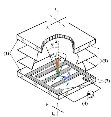
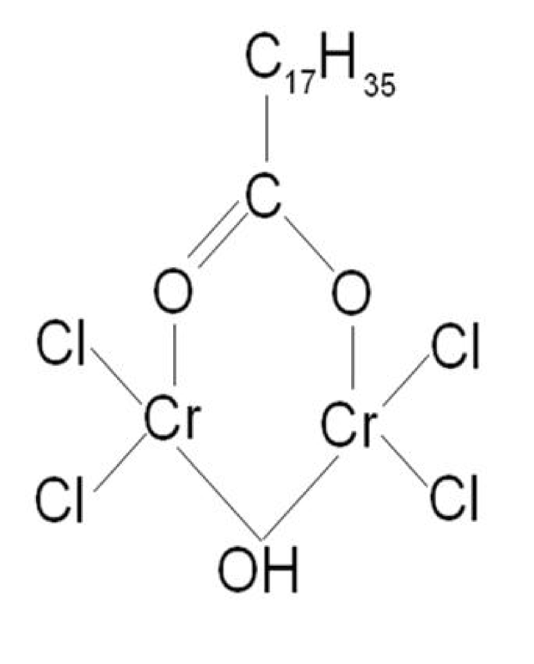
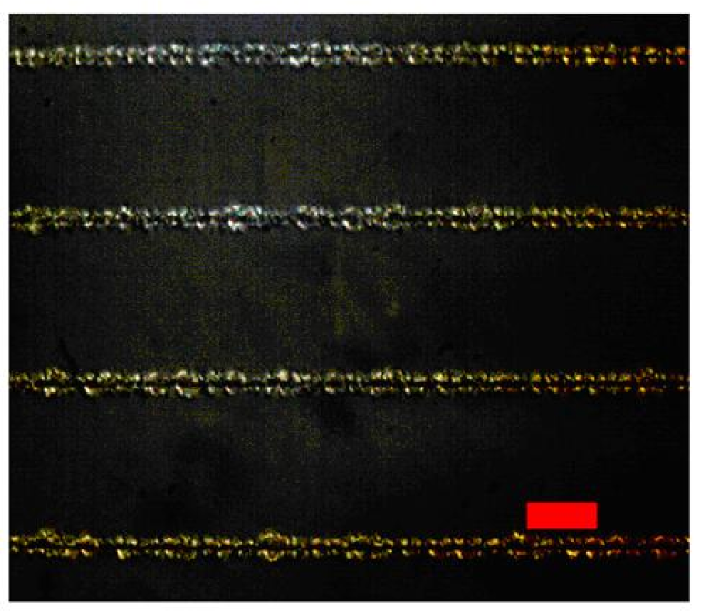
The DHFLC with smectic layers parallel to the surfaces, and with the well-known geometry of in-plane electrodes have been used in our experiments. Figure 1 presents an extensive overview of the electro-optical cell with vertically aligned FLC helix and inter-digital electrode deployed on one of the two glass plates. The inter-digital electrodes with electrode width 2 m and electrode gap of 50 m have been deployed to apply electric field parallel to the smectic layers. The vertical alignment to the DHFLC has been accomplished by spin coating glass plates with 40 nm thick layer of stearic acid chromium salt (its chemical structure is shown in Fig. 3a) followed by soft backing at temperature 100∘C for 10 min. Figure 3b represents the optical microphotograph of the VADHFLC cell which is placed between crossed polarizers in the absence of the electric field.
The FLC-587 with the helix pitch nm (at 22∘C) was used and the thickness of VADHFLC layer, , is maintained at 10 m. The phase transitions sequence of this LC during heating up from the solid crystalline phase is: CrSmCSmAIs, while during cooling from smectic phase crystallization occurs around -10∘C -15∘C. The spontaneous polarization, , and the tilt angle, , at room temperature are 150 nC/cm2 and 36.5∘, respectively.
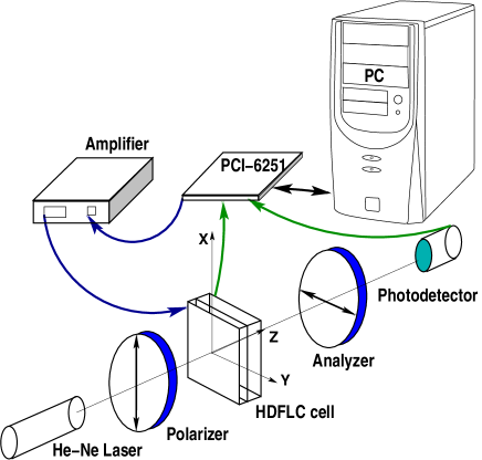
The electro-optical measurements were performed in an automatic regime. The setup scheme used in the experiments is shown in Fig. 4. The basic element of this experimental setup is computer data acquisition (DAQ) board NIPCI 6251 from National Instruments. A photo-detector was connected to input board plate for optical measurements. In our experiments , the output signal, 10 V, was not sufficient therefore wideband power amplifier KH model 7600 from Krohn-Hite Corporation was used. It gives a possibility to have the output signal up to 250 V.
III.2 Results
In this section we present and discuss the results of our measurements.
For a vertically aligned DHFLC cell placed between crossed polarizers (see Fig. 1), the light transmittance is given by
| (30) |
where is the thickness of FLC layer and is the angle between the polarization plane of incident light and the direction of electric field. Figure 5 presents the experimental data for the transmittance, , measured as a function of at temperature 60∘C and . The corresponding values of electrically induced biaxility, , were estimated by using the formula (30) with and m. Referring to Fig. 5, for FLC-587, the saturation value for the vs curve is about . The latter is an order of magnitude greater than the value measured using the conoscopic method in the smectic phase Song et al. (2007) whereas it is of the same order of magnitude as the values reported for the smectic phase Bartoli et al. (1997) and for the bent core nematic phase Nagaraj et al. (2010).
The theoretical curve for the electric field dependence shown in Fig. 5 as a solid blue line was calculated from the relation (23) by using the parameters of DHFLC measured at temperature 60∘C: , , C/m2, , , nm and nm (the parameter was measured using an original method published in Ref. Pozhidaev et al. (2011), was measured by the Sawyer-Tower method Sawyer and Tower (1930) ). As it can be seen from Fig. 5, there are small deviations between the theory and the experimental data when the electric field exceeds 1.5 V/m. This value is very close to and, therefore, it is reasonable to assume that the helix unwinding is responsible for such inconsistency.
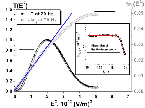
With the help of experimental results for and formula (23), the coefficient has been evaluated at different frequencies. The resulting frequency dependence of is plotted in the insert of Fig. 5. In the low frequency region where kHz, the coefficient is constant and its value nm/V2 is about two orders of magnitude greater than the Kerr constant of nitrobenzene and twice larger than the Kerr constant of the best known PSBPLC Rao et al. (2010).
At kHz, the coefficient decreases with the frequency and shows a pronounced dispersion. From equation (23), this effect can be attributed to the dispersion of the dielectric susceptibility of the Goldstone mode, , in the high frequency region.
In the static limit, the expression for the Goldstone mode susceptibility is as follows Urbanc et al. (1991)
| (31) |
where is the elastic constant and is the twist wave number of FLC helix. This expression can now be combined with the relation (23) to give the corresponding value of . Hence the Kerr coefficient can be increased further by tuning the material parameters , , and that define the susceptibility .
As is described in the caption of Fig. 2, in the presence of electric field parallel to smectic layers, the two optical axes of the VADHFLC cell, are rotated through the angle (see formula (29) and Fig. 2) in the plane normal to the electric field vector. In Fig. 2, this vector is parallel to the axis and defines the optical axis which orientation is unaltered. It follows that, similar to the well-known B effect in nematic liquid crystals, when the polarization vector of incident light is perpendicular to the direction of the electric field, the rotated optical axes remain in the plane of light polarization and the phase modulation of light occurs solely due to the change in the effective refractive index.
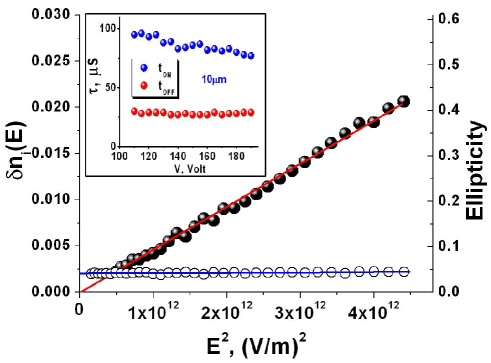
In this case, the polarization states of incident and transmitted light beams are expected to be identical. As it can be seen from Fig. 6, no noticeable modulation in the ellipticity of transmitted light has been observed in our experiments. It is clear that, in the low voltage range where and the electric field dependence of is quadratic, the ellipticity is independent of the electric field. At higher electric fields where is close to , the quadratic approximation for the electric field dependence of breaks down and the ellipticity of the transmitted light begins to grow. The helix unwinding process is responsible for both of these effects.
Insert in Fig. 6 represents the electric filed dependence of the switching on and switching off times, and . It is seen that the VADHFLC device is characterized by the fast response time less than 100 s and thus the modulation frequency could be as high as 2 kHz with saturated electro-optical states. Although PSBPLCs have been recently considered as an emerging display and phase modulating technology, the VADHFLC mode seems to have the advantage of higher Kerr constant supplemented with faster (around an order of magnitude) electro-optical response. Under certain conditions, EO response of DHFLC cells can also be made hysteresis-free Pozhidaev et al. (2012). So, VADHFLCs could find application in many modern electro-optical devices.
IV Discussion and conclusions
In this article we have studied the electro-optical properties of VADHFLC cells with subwavelength pitch that are of key importance for phase modulation. Theoretically, it was found that such cells can be described by the effective dielectric tensor. This tensor was evaluated by using an extended version of the theoretical approach developed in Kiselev et al. (2011).
It was shown that the in-plane electric field changes the principal values of the dielectric tensor so as to transform the zero-field uniaxial optical anisotropy into the biaxial one. In addition, it results in rotation of the optical axes about the electric field vector. It turned out that, in the low voltage limit, the electrically induced changes of the refractive indices are characterized by the quadratic nonlinearity and the above effects can be interpreted as the orientational “Kerr effect”.
Experimentally, we have verified that the electrically induced biaxiality shows the quadratic dependence on electric field in the excellent agreement with the predictions of our theoretical model. For the noncentrosymmetric systems, this type of the characteristic is quite uncommon. In such systems, the Kerr-like nonlinearity is typically masked by the dominating contribution from the Pockels electro-optic effect Melnichuk and Wood (2010).
The measured Kerr constant for VADHFLC is about 27 nm/V2, which is about two orders of magnitude larger than that for the nitrobenzene and twice as large as that for the best known PSBPLC. From equations (23) and (31) it additionally follows that the value of can be increased further by optimizing the FLC parameters such as the spontaneous polarization and the elastic constants with special care of the fundamental constraint of to avoid changes in the polarization characteristics such as the ellipticity and the polarization azimuth.
The 2 phase modulation with the response time less than 100 s, constant ellipticity of transmitted light and hysteresis-free electro-optics are the real advantages of the system. This provides an opportunity for the development of a new generation of phase matrices operating in kilohertz frequency range. Such elements are crucially important for both science and technology and thus could find application in many modern electro-optical devices.
Acknowledgements.
This work was supported in part by grants CERG 612310, CERG 612409 and Russian Foundation of Basic Research Grants 13-02-00598_a, 12-03-90021-Bel_a.References
- Engström et al. (2009) D. Engström, M. J. O’Callaghan, C. Walker, and M. A. Handschy, Appl. Opt. 48, 1721 (2009).
- Ren et al. (2005) H. Ren, Y.-H. Lin, Y.-H. Fan, and S.-T. Wu, Appl. Phys. Lett. 86, 141110 (2005).
- Martínes et al. (2009) J. L. Martínes, A. Martínes-García, and I. Moreno, Applied Optics 48, 911 (2009).
- Hisakado et al. (2005) Y. Hisakado, H. Kikuchi, T. Nagamura, and T. Kajiyama, Adv. Mater. 17, 96 (2005).
- Hasebo et al. (2005) Y. Hasebo, H. Kikuchi, T. Nagamura, and T. Kajiyama, Adv. Mater. 17, 2311 (2005).
- Yan et al. (2010) J. Yan, H.-C. Cheng, S. Gauza, Y. Li, M. Jiao, L. Rao, and S.-T. Wu, Appl. Phys. Lett. 96, 071105 (2010).
- Cheng et al. (2011) H.-C. Cheng, J. Yan, T. Ishinabe, and S.-T. Wu, Appl. Phys. Lett. 98, 261102 (2011).
- Yan et al. (2013) J. Yan, Z. Luo, S.-T. Wu, J.-W. Shiu, Y.-C. Lai, K.-L. Cheng, S.-H. Liu, P.-J. Hsieh, and Y.-C. Tsai, Appl. Phys. Lett. 102, 011113 (2013).
- Zhu et al. (2013) J.-L. Zhu, S.-B. Ni, Y. Song, E.-W. Zhong, Y.-J. Wang, C. P. Chen, Z. Ye, G. He, D.-Q. Wu, X.-L. Song, J.-G. Lu, and Y. Su, Appl. Phys. Lett. 102, 071104 (2013).
- Love and Bhandari (1994) G. D. Love and R. Bhandari, Opt. Commun. 110, 475 (1994).
- Barnik et al. (1987) M. I. Barnik, V. A. Baikaiov, V. G. Chigrinov, and E. P. Pozhidaev, Mol. Cryst. Liq. Cryst. 143, 101 (1987).
- Pozhidaev et al. (1988) E. P. Pozhidaev, M. A. Osipov, V. G. Chigrinov, V. A. Baikalov, L. M. Blinov, and L. A. Beresnev, Sov. Phys. JETP 67, 283 (1988).
- Beresnev et al. (1989) L. A. Beresnev, V. G. Chigrinov, D. I. Dergachev, E. P. Poshidaev, J. Fünfschilling, and M. Schadt, Liq. Cryst. 5, 1171 (1989).
- Chigrinov (1999) V. G. Chigrinov, Liquid crystal devices: Physics and Applications (Artech House, Boston, 1999) p. 357.
- Lee et al. (2005) J.-H. Lee, D.-W. Kim, Y.-H. Wu, C.-J. Yu, S.-D. Lee, and S.-T. Wu, Opt. Express 13, 7732 (2005).
- Kiselev et al. (2011) A. D. Kiselev, E. P. Pozhidaev, V. G. Chigrinov, and H.-S. Kwok, Phys. Rev. E 83, 031703 (2011).
- Hedge et al. (2008) G. Hedge, P. Xu, E. Pozhidaev, V. Chigrinov, and H. S. Kwok, Liq. Cryst. 35, 1137 (2008).
- Ponti and Oldano (2003) S. Ponti and C. Oldano, Phys. Rev. E 67, 036616 (2003).
- Oldano and Rajteri (1996) C. Oldano and M. Rajteri, Phys. Rev. B 54, 10273 (1996).
- Hubert et al. (1998) P. Hubert, P. Jägemalm, C. Oldano, and M. Rajteri, Phys. Rev. E 58, 3264 (1998).
- Ponti et al. (2001a) S. Ponti, M. Becchi, C. Oldano, P. Taverna, and L. Trossi, Liquid Crystals 24, 591 (2001a).
- Markoš and Soukoulis (2008) P. Markoš and C. M. Soukoulis, Wave Propagation: From Electrons to Photonic Crystals and Left-Handed Materials (Princeton Univ. Press, Princeton and Oxford, 2008) p. 352.
- Kiselev (2007) A. D. Kiselev, J. Phys.: Condens. Matter 19, 246102 (2007).
- Kiselev et al. (2008) A. D. Kiselev, R. G. Vovk, R. I. Egorov, and V. G. Chigrinov, Phys. Rev. A 78, 033815 (2008).
- Galatola (1997) P. Galatola, Phys. Rev. E 55, 4338 (1997).
- Ponti et al. (2001b) S. Ponti, C. Oldano, and M. Becchi, Phys. Rev. E 64, 021704 (2001b).
- Etxebarria et al. (2001) J. Etxebarria, C. L. Folcia, and J. Ortega, Phys. Rev. E 64, 011707 (2001).
- Abramowitz and Stegun (1972) M. Abramowitz and I. A. Stegun, eds., Handbook of Mathematical Functions (Dover, New York, 1972).
- Urbanc et al. (1991) B. Urbanc, B. Žekš, and T. Carlsson, Ferroelectrics 113, 219 (1991).
- Melnichuk and Wood (2010) M. Melnichuk and L. T. Wood, Phys. Rev. A 82, 013821 (2010).
- Weinberger (2008) P. Weinberger, Philosophical Magazine Letters 88, 897 (2008).
- Song et al. (2007) J.-k. Song, A. D. L. Chandani, A. Fukuda, J. K. Vij, I. Kobayashi, and A. V. Emelyanenko, Phys. Rev. E 76, 011709 (2007).
- Bartoli et al. (1997) F. J. Bartoli, J. R. Lindle, S. R. Flom, J. V. Selinger, B. R. Ratna, and R. Shashidhar, Phys. Rev. E 55, R1271 (1997).
- Nagaraj et al. (2010) M. Nagaraj, Y. P. Panarin, U. Manna, J. K. Vij, C. Keith, and C. Tschierske, Appl. Phys. Lett. 96, 011106 (2010).
- Pozhidaev et al. (2011) E. Pozhidaev, F. C. M. Freire, C. A. R. Yednak, A. Strigazzi, S. Torgova, V. Molkin, and M. Minchenko, Mol. Cryst. Liq. Cryst. 546, 186 (2011).
- Sawyer and Tower (1930) C. B. Sawyer and C. H. Tower, Phys. Rev. 35, 269 (1930).
- Rao et al. (2010) L. Rao, J. Yan, S.-T. Wu, S.-i. Yamamoto, and Y. Haseba, Appl. Phys. Lett. 98, 081109 (2010).
- Pozhidaev et al. (2012) E. Pozhidaev, V. Chigrinov, A. Murauski, V. Molkin, D. Tao, and H.-S. Kwok, Journal of the SID 20, 273 (2012).