Manipulation in Clutter with Whole-Arm Tactile Sensing
Abstract
We begin this paper by presenting our approach to robot manipulation, which emphasizes the benefits of making contact with the world across the entire manipulator. We assume that low contact forces are benign, and focus on the development of robots that can control their contact forces during goal-directed motion. Inspired by biology, we assume that the robot has low-stiffness actuation at its joints, and tactile sensing across the entire surface of its manipulator. We then describe a novel controller that exploits these assumptions. The controller only requires haptic sensing and does not need an explicit model of the environment prior to contact. It also handles multiple contacts across the surface of the manipulator. The controller uses model predictive control (MPC) with a time horizon of length one, and a linear quasi-static mechanical model that it constructs at each time step. We show that this controller enables both real and simulated robots to reach goal locations in high clutter with low contact forces. Our experiments include tests using a real robot with a novel tactile sensor array on its forearm reaching into simulated foliage and a cinder block. In our experiments, robots made contact across their entire arms while pushing aside movable objects, deforming compliant objects, and perceiving the world.
I Introduction
Research on robot manipulation has often emphasized collision free motion with occasional contact restricted to the robot’s end effector. In essence, most of the manipulator’s motion is intended to be free-space motion and unintended contact is considered to be a failure of the system. In contrast, animals often appear to treat contact between their arms and the world as a benign and even beneficial event that does not need to be avoided. For example, humans make extensive contact with their forearms even during mundane tasks, such as eating or working at a desk.
Within this paper, we present progress towards new foundational capabilities for robot manipulation that take advantage of contact across the entire arm. Our primary assumption is that, for a given robot and environment, contact forces below some value have no associated penalty. For example, when reaching into a bush, moderate contact forces are unlikely to alter the robot’s arm or the bush in undesirable ways. Likewise, even environments with fragile objects, such as glassware on a shelf, can permit low contact forces. While some situations merit strict avoidance of contact with an object, we consider these to be rare, and instead focus on default strategies that allow contact.
In order to keep contact forces low enough to avoid penalties, we further assume that the robot arm has compliant actuation at its joints and tactile sensing across all of its surfaces. Low-stiffness compliant actuation can reduce contact forces due to perturbations, error, and other sources. Tactile sensing enables direct monitoring of contact forces (and the distribution of contact forces). These assumed hardware capabilities for the robot’s actuation and sensing are also analogous to capabilities found in animals.
Our main contribution in this paper is a novel controller that enables a robot arm to move within an environment while regulating contact forces across its entire surface. The controller uses model predictive control (MPC) with a time horizon of length one and a linear quasi-static mechanical model. At each time step, the controller constructs a model and solves an associated quadratic programming problem in order to minimize the predicted distance to a goal subject to constraints on the predicted contact forces.
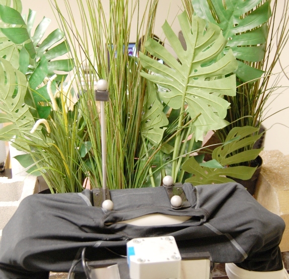
We also empirically evaluate our controller’s performance with respect to the task of haptically reaching to a goal location in high clutter (see Fig. 1). We assume that the clutter can consist of a variety of fixed, movable, and deformable objects, and that the robot does not have a model of the environment in advance. This task is representative of real-world challenges for robots, such as retrieving objects from rubble, foliage, or the back of a shelf. It is also representative of an animal reaching for food while foraging.
We tested our controller under a variety of conditions with a simulated robot, a real robot with simulated tactile sensing, and a real robot with real tactile sensors across its forearm. For many of the tasks, the robots compressed, bent, or moved objects out of the way with their arms while reaching the goal location. Our results demonstrate that the model predictive controller has a higher success rate and lower contact forces compared to a baseline controller.
I-A Biological Inspiration
![[Uncaptioned image]](/html/1304.6146/assets/figures/raccoon_nest_box_cropped.jpg)
![[Uncaptioned image]](/html/1304.6146/assets/figures/monkey_in_tree_cropped.jpg)
![[Uncaptioned image]](/html/1304.6146/assets/figures/noodling_1.jpg)
![[Uncaptioned image]](/html/1304.6146/assets/figures/noodling_2_cropped.jpg)
![[Uncaptioned image]](/html/1304.6146/assets/figures/human_reach/shelf_cropped.jpg)
![[Uncaptioned image]](/html/1304.6146/assets/figures/human_reach/fridge_cropped.jpg) \captionof
\captionof
figure We propose foundational capabilities for robotic manipulation that will enable robots to make and exploit contact with their environment. While foraging for food, animals and humans make contact at multiple locations on their arm and operate in cluttered environments. (a) A raccoon reaches into a bird house to find eggs and young (webpage, 2011a). (b) A Long-tailed Macaque grasps fruit in dense foliage (webpage, 2011b). (c) When noodling, people find catfish holes from which to pull fish out (webpage, 2011c). (d)-(e) A person makes contact along his forearm while reaching for an object in the back of a shelf and refrigerator. (All images used with permission)
Animals serve as an inspiration for our research (see Fig. I-A), especially in terms of the capabilities they exhibit, their sensing, and their actuation.
Animals dramatically outperform current autonomous robots within unstructured environments, such as when foraging in dense foliage. During these activities, animals often make contact with the world at multiple locations along their arms, and reach into visually occluded spaces.
Touch is an important sensory modality for successful foraging (Dominy, 2004; Iwaniuk and Whishaw, 1999). In general, animals can usefully manipulate the world in the absence of vision. As an extreme example, the star-nosed mole uses the sense of touch almost exclusively while foraging (Catania, 1999). Humans also competently manipulate the world without vision, as the reader can demonstrate by haptically exploring the underside of a nearby table. Inspired by these capabilities, our goal is to develop methods that degrade gracefully when deprived of non-haptic modalities, such as vision and audition.
Animals also serve as inspiration for our decision to assume the presence of whole-body tactile sensing. Although whole-body tactile sensing is currently rare in robotics, it is nearly ubiquitous in biology, which suggests that it is advantageous for operation in unstructured environments. Organisms from small nematodes to insects and mammals are able to sense forces across their entire bodies (Bianchi, 2007; Goodman, 2006; Lumpkin et al, 2010; Lederman and Klatzky, 2009). Sensing forces also plays an important role in avoiding injury. For example, loss of sensitivity in a human diabetic’s foot is a strong risk factor for injuring the foot (Sims Jr et al, 1988). As has often been noted, tactile sensing also supports human manipulation (Johansson and Flanagan, 2009).
Compliant actuation at the joints is another common characteristic in animals that we have chosen to emulate (Hogan, 1984; Alexander, 1990; Migliore et al, 2005). Robotics researchers have demonstrated that compliant joints lower interaction forces during incidental contact and can be beneficial for unmodeled and dynamic interactions (J. Pratt and Pratt, 2001; Pratt and Williamson, 1995; Buerger and Hogan, 2007; Pratt, 2002). This capability is now relatively common within robotics, although we use stiffnesses that tend to be lower than other published research. For example, in some postures, the stiffness at the end effector is a factor of five lower than those reported by DLR in Ott et al (2007). The values we use are similar to measured stiffnesses of humans during planar reaching motions (Shadmehr, 1993).
I-B Benefits of Whole-body Contact and Tactile Sensing
Given our emphasis on whole-body contact and whole-body tactile sensing, we now illustrate some of the performance benefits associated with these design decisions.
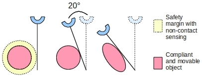
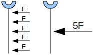
One benefit of allowing contact with the arm is the increased effective range of motion of the manipulator. As illustrated in Fig. 2, the performance loss due to avoiding contact is exacerbated by safety margins and an inability to apply forces that compress or move objects. Similarly, if the robot has a compliant exterior, avoiding contact forfeits the additional range of motion achievable by compressing this exterior. Animals appear to use this method to achieve greater motion while in contact and squeeze through openings. The reader can gain some insight into this by noting the compressibility of the human forearm that results from the soft tissues surrounding the endoskeleton.
Whole-body tactile sensing with high spatial resolution also has advantages in terms of distinguishing between distinct contact configurations and force distributions, and measuring forces with high sensitivity. Prior research has attempted to use the geometry of links, measurements of joint torques and force-torque sensors to estimate contact properties (e.g, Eberman and Salisbury (1990); Bicchi et al (1993); Kaneko and Tanie (1994); De Schutter et al (1999)). However, interpretation of data from these sensors can often be ambiguous in multi-contact situations (Salisbury, 1984). In practice, the estimation can also be sensitive to the configuration of the manipulator, the fidelity of the torque estimates, and friction and flexibility at the joints (Dogar et al, 2010; Eberman, 1989).
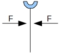
Fig. 3 shows two examples of contact conditions that will result in ambiguity if a robot only uses joint torque sensing or force-torque sensors mounted at the joints. In the first example, the resultant force and torque on the robot arm is zero, but it is wedged between two contacts. The second example illustrates that contact over a large area, and a high force at a single point can result in the same total resultant force and torque.
Distinguishing among these situations can be advantageous. For example, a high total force distributed over a small area, such as due to contact with the edge of a cinder block or a small branch, has greater potential to damage the robot or the world, respectively. Similarly, the same large total force distributed across a large area due to contact with tall grass or leaves is less likely to damage the robot or the world. Moreover, the geometries associated with distinct contact regions, such as a rigid point, line, or plane, imply distinct options for subsequent movement.
More generally, for many manipulation tasks, the manipulator primarily influences the world via contact forces with other forms of physical interaction, such as heat transfer, being uncontrolled or irrelevant. As such, we expect that direct measurement of contact forces will enable superior manipulation capabilities.
I-C Challenges Associated with Reaching in High Clutter
For this paper, we focus on the task of reaching to a goal location in high clutter. This entails a number of challenges, including the following:
-
•
Lack of non-contact trajectories: As clutter increases, approaches that avoid contact with the environment will have a diminishing set of trajectories that can successfully perform the task. If the robot is interacting with movable or compliant objects, such as foliage, reaching the goal while applying low forces might be possible but non-contact trajectories may not exist.
-
•
Contact with only the end effector may be inefficient or infeasible: Removing or rearranging the clutter by making serial contact with only the end effector may be inefficient or infeasible. For example, given an environment with multiple compliant objects (e.g., plants) it may not be possible to first bend each of the objects out of the way one at a time without plastic deformation. Instead, an efficient solution would be to directly reach to the goal and allow multiple contacts to occur with the compliant objects and the arm.
-
•
Clutter can consist of unique objects and configurations that have not been encountered before: For some types of natural clutter, such as dense foliage, each object encountered can be unique. Objects could be fixed, movable, rigid, deformable, granular, fluid-like, and dynamic. Likewise, the configuration of the environment can be unique. Statistical properties may be informative, but a specific environment may only be encountered once by the robot.
-
•
Observation of geometry is obstructed: Low visibility due to occlusion will often prevent conventional line of sight sensors, such as cameras and laser range finders, from modeling the geometry of the clutter in advance (see Fig. 1).
-
•
Mechanics are difficult to infer without contact: Non-contact sensing provides limited ability to infer the mechanical properties of the clutter, such as whether or not an object can be bent or moved out of the way. Likewise, objects may be mechanically coupled in complicated ways, such as through adhesion or unobserved rigid connections.
Notably, many approaches to manipulation are poorly matched to address these challenges. For example, approaches that rely on preexisting detailed models, estimation of models via conventional line-of-sight sensing, or collision-free motions with the arm would fare poorly under real-world conditions at which animals excel (e.g., Kavraki and LaValle (2008); Stilman et al (2007); Srinivasa et al (2009); Saxena et al (2008)).
I-D Our Approach
In contrast, our approach directly addresses these challenges associated with high clutter due to the following properties:
-
•
We explicitly allow multiple contacts across the entire surface of the arm: Our approach assumes that the entire surface of the manipulator is covered with pressure sensing elements (tactile pixels or taxels), and that every taxel could be simultaneously in contact with the world at any given moment.
-
•
We do not require a detailed model of the environment prior to contact: Our approach only requires that initial parameters appropriate for the robot, the environment, and the task be provided to the robot’s control system in advance. For our current controller, this includes the force magnitude below which no penalty is expected, and the initial stiffness estimate assigned to new contacts.
-
•
We only require contact-based sensing: Our approach only requires contact-based sensing. Our current controller only makes use of haptic sensing in the form of joint angles111Due to the low-stiffness virtual visco-elastic springs at the robot’s joints, the joint angles over time directly relate to the joint torques. and taxel responses. Through this contact-based sensing and a kinematic model of its own arm, the controller estimates the instantaneous contact geometry and the stiffness associated with each contact in order to generate a local model. Future work may make use of non-contact sensing, which would be complementary, but this is not required.
I-E Organization of this Paper
The rest of this paper is organized as follows. In Sec. II we discuss related research on manipulation in clutter, multi-contact manipulation, motion planning with deformable objects, robot locomotion, and model predictive control. Next, in Sec. III, we derive our model predictive controller for the task of reaching to a goal location in a cluttered environment. We describe the hierarchy of controllers running on our robot, the linear quasi-static model that the controller uses, and the quadratic program that the controller solves at each time step.
We then describe three testbeds that we used to empirically test the performance of our controller (Sec. IV) and the baseline controller that we compared our model predictive controller against (Sec. V). Next, we describe the experiments that we ran in Sec. VI. We end with a discussion of our work in Sec. VII and conclude with a brief summary of our results in Sec. VIII.
II Related Work
II-A Manipulation in Clutter
Within this paper, our goal is to enable robots to reach to a goal location in cluttered environments and manipulate with multiple contacts across the entire arm using haptic sensing.
In contrast, robotics research has often addressed the task of generating collision free trajectories (e.g, Lozano-Perez (1987); LaValle and Kuffner (2001); Kavraki and LaValle (2008)), generating reaching motions in free space (e.g, Metta et al (2011); Stulp et al (2009); Hersch and Billard (2006)), and manipulating objects in uncluttered environments (e.g, Natale and Torres-Jara (2006); Jain and Kemp (2010a); Hsiao et al (2010); Pastor et al (2011); Romano et al (2011); Saxena et al (2008)).
Research has also looked at the problem of manipulation in cluttered environments. However, most prior research on manipulation in clutter with autonomous control and during teleoperation (e.g, Leeper et al (2012)) restricts contact between the robot and its environment to the end effector. Often, prior research has also used non-contact, line of sight sensors and required pre-existing models of objects.
Stilman et al (2007) describes an algorithm for planning in an environment with movable obstacles. Within software simulation, the planner uses geometric models of all the objects in the world to enable a robot to rearrange clutter by grasping and moving objects, and opening doors.
Dogar and Srinivasa (2011) presents a framework to plan a sequence of actions such as pushing and grasping objects to rearrange clutter prior to grasping an object. The actions currently used within the framework restrict contact to the robot’s end effector and avoid other contact with the world. The implementation relies on estimating the pose of objects in the environment using visual and geometric models (created during an off-line modeling stage). Additionally, for now, the planned actions are executed without sensor feedback.
Mason et al (2011) describes a simple end effector design that can be used to grasp a single marker from a cluttered pile of nearly identical markers, and haptically estimate the marker’s pose after grasping it. This is the most similar work in spirit to ours, since it investigates manipulation in high clutter, does not use a detailed model of the environment prior to contact, allows multiple contacts across the surface of the end effector, and uses haptic sensing. Their “Let the fingers fall where they may.” approach to grasping in clutter has other notable similarities to our approach to reaching in clutter. Both approaches use greedy controllers that are run iteratively, and both approaches ignore the details of how the clutter responds to the robot’s actions. However, our approach performs more complex feedback-based control of the manipulator and does not use a simple mechanism nor simple sensing, which they emphasize. This is in part because we wish to regulate the contact forces. More degrees of freedom also appear to improve the performance of our controller, although we do not yet have reportable results to support this claim. In addition, we focus on reaching in clutter, rather than grasping, and present empirical results for diverse environments, in contrast to their experiments with a collection of durable, rigid, nearly-identical, manufactured objects.
II-B Multi-contact Manipulation
Park and Khatib (2008) presents a framework for controlling a robot with multiple contacts along the links. It generalizes previous direct force control methods (Raibert and Craig, 1981; Khatib, 1987) to not require force and motion to be along orthogonal directions in Cartesian space and to allow for contacts at points other than the end effector.
This method requires a full dynamic model of the robot and assumes stationary and rigid contacts. Further, this framework assumes that the robot has at least six degrees of freedom (DoF) for each contact, to control the contact force and torque vector (Sentis et al, 2010). A seven degree of freedom arm, like the robot arm that we use, with multiple contacts is unlikely to have six independent degrees of freedom for each contact.
Using this framework, results have been shown in simulation (Sentis and Khatib, 2005; Sentis et al, 2010), and on a real robot in relatively controlled settings (Petrovskaya et al, 2007). No results have been shown in cases where the robot makes additional unpredicted contact with the environment or loses contact at some locations.
In contrast, our controller uses a linear quasi-static model of the robot’s interaction with the environment and does not assume that the robot has six degrees of freedom for each contact. On a real robot with a tactile skin sensor, we demonstrate that our controller can operate in cluttered environments with multiple unpredicted contacts with compliant, rigid, movable, and fixed obstacles across the entire arm of the robot.
Research in motion planning for humanoid robots has shown that a robot with geometric models of its environment can make contact at multiple, predetermined locations on its body to better perform a task, such as lean on a table to take a large foot step (Legagne et al, 2011), use contacts at hands and knees to climb a ladder in simulation (Hauser et al, 2005), and use contact between the hand and a table while sitting down (Escande and Kheddar, 2009). These approaches require a complete geometric model of the world (which can be difficult or impossible to obtain unless the robot is operating in a controlled environment), assume stationary and rigid contacts, and do not incorporate sensor feedback as the robot (real or simulated) executes the planned kinematic trajectory. These approaches attempt to maintain balance on the humanoid robot while we assume that the robot is statically stable.
II-C Motion Planning with Deformable Objects
Manipulation research often assumes that objects that the robot interacts with are rigid. At the same time, there is research on motion planners that allow the robot to make contact with, and push into deformable objects (e.g. Frank et al (2011); Rodriguez et al (2006); Patil et al (2011)). However, these approaches assume knowledge of the specific configuration of the objects and require accurate and detailed models of how objects deform. We avoid these assumptions in our work.
These approaches build object deformation models by using data-driven methods for a specific object, or computationally expensive physics simulations that use the physical properties of the objects. Accurate object deformation models can be hard to obtain in realistic and cluttered environments. Additionally, if multiple objects are in contact with each other and the specific configuration is unknown, then building these models before making contact may not be feasible.
II-D Robot Locomotion
Our approach to robot manipulation has similarities to approaches that have been successful for robot locomotion. For example, researchers have developed robots that locomote in cluttered environments without detailed geometric models of the terrain nor planning over long time horizons (Saranli et al, 2001; Raibert et al, 2008). Likewise, whole body contact, and contact in general, has not been considered undesirable. For example, robots have used contact all over their bodies to traverse the ground and swim in granular media (McKenna et al, 2008; Maladen et al, 2010). Additionally, the use of simple mechanical models, compliance, and force sensing is common for robot locomotion (Raibert et al, 2008; Pratt, 2002; J. Pratt and Pratt, 2001; Garcia et al, 1998).
II-E Model Predictive Control
One of the initial application areas for model predictive control (MPC) was chemical process control (Garcia et al, 1989). It is often referred to as receding horizon control when used for control of aerial vehicles (Bellingham et al, 2002; Abbeel et al, 2010). MPC has also been used in research in robot locomotion (e.g, Wieber (2006); Manchester et al (2011); Erez et al (2011)), and for controlling robot manipulators (e.g, Ivaldi et al (2010); From et al (2011); Kulchenko and Todorov (2011)).
III Model Predictive Controller
The controller that we have developed uses linear model predictive control (MPC) with a time horizon of length one. Specifically, using the notation of Morari and Lee (1999), our controller uses a linear discrete time model of the system,
| (1) |
where is the state of the system and is the control input.
At each time step, , the controller computes a sequence of control inputs, , to minimize a quadratic objective function of and , subject to linear inequality constraints on and , where is the length of the time horizon of the model predictive controller. This defines a quadratic program (Morari and Lee, 1999). The controller then uses only the first control input, i.e. it sets , and reformulates the quadratic program at the next time step. In this paper, we use a time horizon of length one , and recompute the and matrices in Eq. 1 at each time step.
In the rest of this section, we describe our model predictive controller for manipulation with multiple contacts. First, in Sec. III-A, we give an overview of the controller that we have developed. Next, we present the hierarchy of controllers running on our robot in Sec. III-B. In Sec. III-C we describe the linear quasi-static model that our model predictive controller uses, and detail the quadratic program that we solve at each time step Sec. III-D. We then describe some extensions to the quadratic program in Sec. III-E.
III-A Overview of the One-Step Model Predictive Controller
The model predictive controller that we have developed uses a linear discrete time model of the system, a one step time horizon, and attempts to move the end effector along a straight line to the goal subject to constraints on the predicted contact forces.
It explicitly allows the robot to apply any force less than a don’t care force threshold at each contact. Our controller has the following parameters that influence its behavior:
-
•
Goal location : This is the location that the controller attempts to move the end effector to.
-
•
Contact stiffness matrices : These are the controller’s estimates of the stiffness matrices for each contact location along the arm. In this paper, we assume that the stiffness at each contact is non-zero along the direction normal to the surface of the robot arm and is zero in the other directions.
-
•
Don’t care force thresholds : The controller attempts to keep the force at each contact below this value, and applies no penalty to contact forces below this threshold.
-
•
Maximum rate of change of contact force : This term limits the predicted change in the contact force over one time step with the goal of preventing large and abrupt changes in the contact force.
-
•
Safety force threshold : If the contact force, , exceeds this safety threshold value, the controller stops updating the virtual trajectory and we report it as a failure of the controller.
In this paper, we perform experiments on three different testbeds, described in Sec. IV. The precise meaning of contact, and thus the don’t care force threshold and other parameters of the model predictive controller, depends on the specific testbed, as described in Sec. IV-E.
III-B Control Structure
In this work, we use a hierarchical control structure with an inner 1kHz real time joint space impedance controller, termed “simple” impedance control by Hogan and Buerger (2005), and an outer model predictive controller that runs at 50-100Hz, as shown in Fig. 4.
Researchers have argued for the benefits of robots with low mechanical impedance (Pratt, 2002; Buerger, 2006). As has often been noted, these arguments are particularly relevant for manipulation in unstructured environments, since robots are likely to be uncertain about the state of the world. At minimum, low impedance can reduce the forces and moments resulting from unpredicted contact, and thus reduce the risk of damage to the robot, environment, and nearby people.
III-B1 “Simple” Impedance Control
For a detailed description and analysis of this form of impedance control, we refer the reader to Hogan and Buerger (2005). The input to the 1kHz “simple” impedance controller, , is called a virtual trajectory. The controller uses feedback from the joint encoders to command torques at the joints, , that are given by
| (2) |
and are constant diagonal joint-space stiffness and damping matrices, and are the current joint angles and joint velocities, and is a gravity compensating torque vector which is a function of . The robot arm has joints.
As a result, the closed loop system behaves as if the arm is connected to the joint-space virtual trajectory, , via torsional visco-elastic springs at the joints. If is held constant, “simple” impedance control can be shown to result in stable interaction with passive environments for contacts all over the arm (Hogan and Buerger, 2005; Hogan, 1988).
Unlike other approaches to force control and impedance control, “simple” impedance control does not explicitly model the dynamics of the arm nor the impedance at the end effector (Sentis et al, 2010; Albu-Schaffer et al, 2003). We have found in our previous work that in practice this form of impedance control, also referred to as “equilibrium point control”, allows the robot to interact with the world in a stable, compliant, and effective way (Edsinger and Kemp, 2007a, b; Jain and Kemp, 2009a, b, 2010b).
III-B2 Model Predictive Controller
The model predictive controller is part of the outer feedback control loop that runs between 50-100Hz in our implementation, as shown in Fig. 4. The input is a goal location, , that the controller attempts to reach. The controller uses feedback from the joint encoders and the tactile skin to compute , an incremental change in the virtual joint-space trajectory. This is the control input, , of Eq. 1.
We will now derive the model predictive controller.
III-C Linear Discrete-Time Model
In this section, we derive a discrete time linear quasi-static model, similar to Eq. 1, for the arm and its interaction with the world that our model predictive controller uses. Specifically, the model will be of the form
| (3) |
where is the state of the system (vector of joint angles for a robot with joints), the control input is the incremental change in the joint-space virtual trajectory of the impedance controller, and .
We begin by assuming that the robot has a fixed and statically stable mobile base and the arm is in contact with the world at locations. We denote the contact as . The equations of motion in joint space are
| (4) |
where is the force at the contact, is the Jacobian matrix for contact , is the vector of torques due to gravity at each joint, and is the vector of torques applied by the actuators at the joints. Eq. 4 ignores effects such as friction at the joints, but is commonly used in robotics (Featherstone and Orin, 2008).
Combining the equations of motion (Eq. 4) with the impedance control law (Eq. 2) gives us the model of the arm and its interaction with the world as
| (5) |
In this paper, as an approximation, we assume that the dynamics are negligible, and that the gravity compensating torques are perfect. So, we remove all terms with or from Eq. 5, and set to get
| (6) |
which is a quasi-static model. In Eq. 6, the torques at the joints due to the contact forces (left-hand side) balance the torques applied by the actuators in the joints (right-hand side).
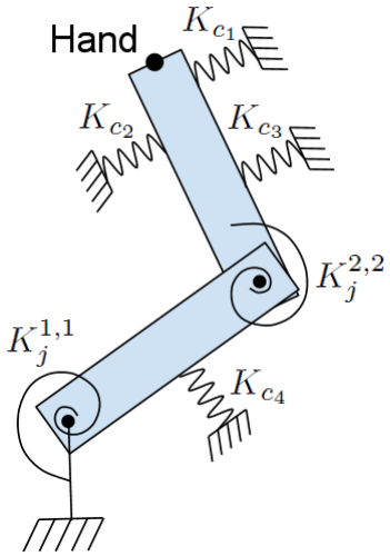
For the contact model, we ignore friction at the contacts and assume that each contact behaves like a linear spring with the contact force along the normal vector of the surface of the robot arm. These assumptions are similar to the Hertzian contact model (Kao et al, 2008; Johnson and Johnson, 1987). This results in a mechanical model with torsional springs at the joints and linear springs at the contacts, shown in Fig. 5.
If we take the difference of Eq. 6 at time instants and , we get
| (7) |
We assume that the change in the configuration of the arm in one time step, , is small and we approximate with . This reduces Eq. 7 to
| (8) |
where is the control input of the model predictive controller, see Eq. 3 and Fig. 4.
Using the linear elastic spring model for the contacts, shown in Fig. 5,
| (9) |
where . We can now use Eq. 9 to rewrite Eq. 8 as
| (10) |
is the sum of a positive definite matrix, , and positive semi-definite matrices, , and is therefore positive definite and invertible.
III-D Quadratic Program to Compute
In this section we describe the quadratic program (QP) that our model predictive controller solves at each time step.
Specifically, using the terminology of Boyd and Vandenberghe (2004), our optimization variable is , an incremental change in the joint-space virtual trajectory, and we minimize a quadratic objective function subject to linear equality and inequality constraints. We use the open source OpenOpt framework to solve the quadratic program (Kroshko, 2011).
In this paper, the objective function is of the form
| (11) |
where are quadratic functions of the optimization variable , and are empirically tuned scalar weights.
We set up the quadratic program such that the solution, , will result in the predicted position of the end effector which is closest to a desired position subject to constraints on the predicted change in the joint angles and contact forces.
III-D1 Move to a Desired Position
The first term of quadratic objective function of Eq. 11 attempts to move the end effector to a desired position. It is of the form
| (12) |
where is the predicted motion of the end effector (or hand) and is the desired change in the end effector position in one time step. In this paper, we attempt to move the end effector in a straight line towards the goal, , and compute
| (13) |
where is a small constant distance. We use the kinematic relationship
| (14) |
where is the Jacobian at the end effector (or hand), and is the change in the joint angles predicted by the linear quasi-static discrete time system model of Eq. 10. We can now express the objective function as a quadratic function of :
| (15) |
III-D2 Joint Limits
We also add two linear inequality constraints to keep the predicted joint angles within the physical joint limits. These are of the form
| (16) |
where and are the difference between the minimum and maximum joint limits and the current configuration of the robot. Using Eq. 10 we can rewrite the inequalities of Eq. 16 as linear inequalities in .
III-D3 Contact Forces
For each contact, we attempt to restrict the contact force to be below a don’t care force threshold and limit the predicted change of the contact force, , in one time step. This results in two inequalities for each contact,
| (17) | ||||
| (18) | ||||
| (19) |
is a threshold on the maximum allowed predicted change in the contact force in one time step. The term in Eq. 19 explicitly allows contact forces below without any additional cost.
III-E Extensions to the Quadratic Program
In this section, we describe three extensions to the quadratic program of the previous section (Sec. III-D) that we use in the experiments of Sec. VI.
III-E1 Squared Magnitude of
To discourage large changes in the joint torques in one time step, we add a term
| (20) |
to the objective function after multiplying it with a scalar weight , see Eq. 11. This term is useful in preventing large motions of the redundant degrees of freedom.
III-E2 Decrease Contact Forces Above Don’t Care Threshold
Due to modeling errors and unmodeled dynamics, the force at some contact (or a number of contacts) can go above the don’t care force threshold . In this case, we modify the inequality constraints of Sec. III-D3 for these contacts to prevent an increase in the predicted force. We also add an additional term to the objective function that encourages the controller to decrease the forces at these contacts. This is of the form
| (21) |
where is the desired change the contact force in one time step and is the change in the contact force as predicted by the linear model that our controller uses. We set as a force with a constant magnitude and a direction opposite to . Using Eqns. 9 and 10, we can express as a quadratic function of .
III-E3 Limits on the Virtual Trajectory
On the robot Cody, described in Sec. IV-B, the joint-space impedance controller limits the virtual trajectory to be within the physical joint limits. To account for this, we add two additional linear constraints on :
| (22) |
IV Experimental Testbeds
We evaluated our model predictive controller using three different testbeds: 1) a software simulation testbed with a 3 DoF planar arm, 2) a hardware-in-the-loop skin simulation testbed with a real 7 DoF arm, and 3) a skin sensor covering the forearm of a real 7 DoF arm. The same MPC code written in Python runs on all three experimental testbeds. For visualization, we use the rviz program which is part of the Robot Operating System (Quigley et al, 2009).
IV-A Software Simulation
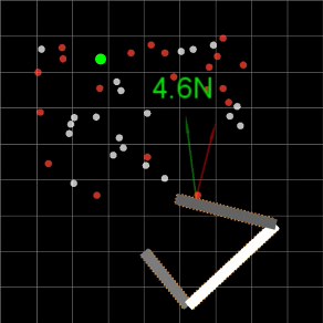
This testbed allows us to simulate a large number of trials. We use the open source physics simulation library, Open Dynamics Engine (Smith et al, 2011), to simulate a planar arm with three rotational joints, a 1kHz joint-space impedance controller, and tactile skin covering the entire surface of the arm with a simulated taxel resolution of 100 taxels per meter. Fig. 6 shows a visualization of the simulated robot, tactile skin, and taxels.
The simulated three link planar arm has kinematics and joint limits similar to a human operating in a plane parallel to the ground at shoulder height with a fixed wrist. The three joints correspond to torso rotation, shoulder, and elbow.
The arm interacts with rigid cylindrical obstacles that are either fixed or movable. In isolation, a movable object can slide in the plane if the force applied to it exceeds friction , while the fixed obstacles remain stationary regardless of the force applied to them.
IV-B The Robot
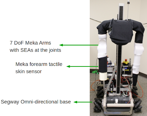
Fig. 7 shows the robot Cody that we use for experiments in this paper. Cody has two compliant 7 DoF arms from Meka Robotics with series elastic actuators (SEAs) for torque control at each degree of freedom. The joint space impedance control on Cody runs at 1kHz. Cody has a Segway omnidirectional mobile base which we control with a PID controller that uses visual odometry as described in our previous work (Killpack et al, 2010).
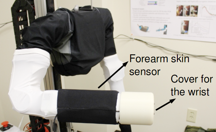
As part of this research we have developed a tactile skin sensor that covers the right forearm of Cody, as shown in Fig. 8 and described in Sec. IV-C. We currently have tactile skin covering its right forearm only.
For experiments in realistic conditions, described in Sec. VI-D, we wanted to be able to sense contact forces on more distal parts of the arm. To do this, we 3D printed a cylindrical cover for the wrist of the robot, shown in Fig. 8. We use the wrist force-torque sensor to measure the resultant force applied to the environment by the distal part of the arm beyond the forearm. Due to this cover, the experiments with the forearm tactile skin sensor use only the first four degrees of freedom of the arm.
IV-C Real Tactile Skin Sensor
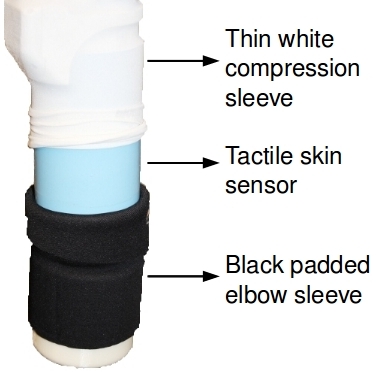
Fig. 8 shows the tactile skin sensor that covers the forearm of the robot Cody. Meka Robotics and the Georgia Tech Healthcare Robotics Lab developed the forearm tactile skin sensor, which is based on Stanford’s capacitive sensing technology, as described in Ulmen et al (2012).
The forearm skin sensor consists of 384 taxels arranged in a array. There are 16 taxels along the length of the cylindrical forearm and 24 taxels along the circumference. Each element has a dimension of and a sensing range of . We can obtain the taxel array sensor data at 100Hz using Robot Operating System (ROS) drivers.
On the robot Cody, we added two additional layers on top of the forearm skin sensor to cover the open parts of the joints, protect the skin sensor, and make the exterior of the arm low friction. These are shown on the right in Fig. 8. The white sleeve is a thin neoprene McDavid compression arm sleeve, and the black layer is a padded Ergodyne neoprene elbow sleeve designed for human athletes.
IV-D Hardware-in-the-loop Skin Simulation
Since we currently do not have whole-arm tactile skin on Cody, we have built a hardware-in-the-loop simulation testbed to be able to simulate whole-arm skin and test our controller on a real robot arm.
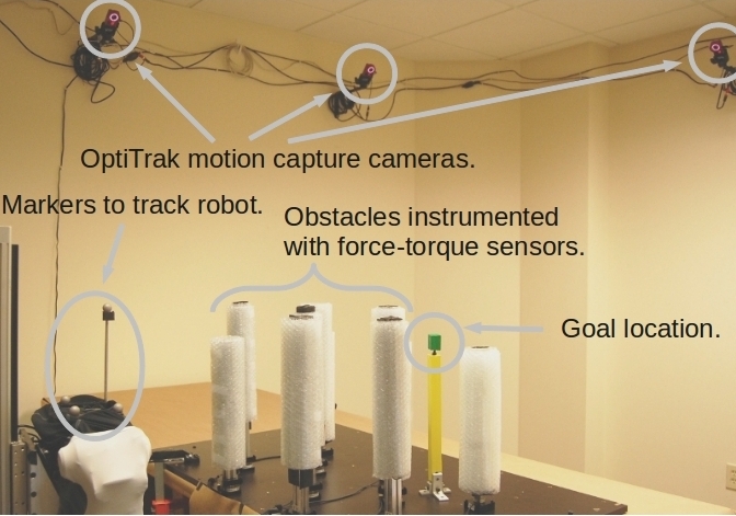
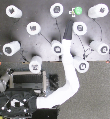
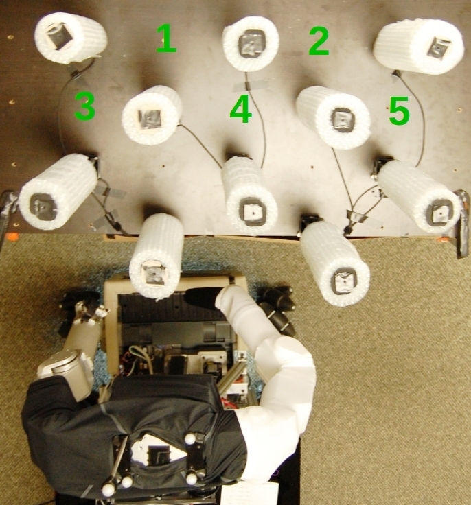
Fig. 9 shows the current implementation of this testbed. We use an OptiTrak motion tracking system to register the positions of the obstacles, and the pose of the the robot in a common coordinate frame. We then use geometric collision detection from OpenRAVE (Diankov and Kuffner, 2008) and models of the robot arm and obstacles to estimate the region over which each link of the robot makes contact with the obstacles.
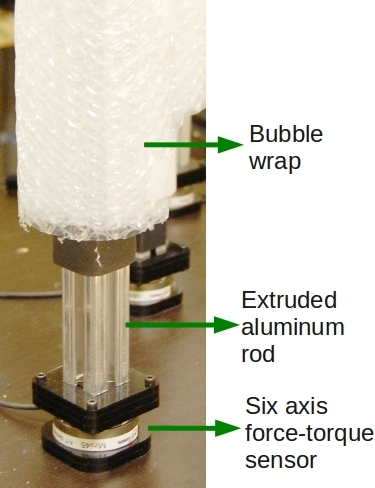
We have also mounted a six-axis force-torque sensor at the base of each obstacle to measure the resultant force applied to each obstacle. This testbed allows us to simulate skin on a real robot with 7 DoF arms.
For every instrumented obstacle and robot link pair, we estimate at most one contact location as the centroid of the contact region and use the force measured by the force-torque sensor as the contact force. If multiple links make contact with the same obstacle, we divide the force vector’s magnitude equally among all the links.
IV-E Tactile Feedback in the Different Testbeds
There are differences in the tactile feedback in each of the three testbeds that change the precise meaning of contact force and contact location.
Within the software simulation testbed (Sec. IV-A), contact force refers to the normal component of the force applied by the robot to the environment over the surface covered by one taxel of the simulated tactile skin. Contact location refers to the centroid of the simulated taxel.
Within the hardware-in-the-loop skin simulation testbed (Sec. IV-D), contact force refers our estimate of the force that a link of the real robot applies to an object. We use at most one contact location between each link of the robot and an object as the centroid of the contact region computed using geometric collision detection. We currently do not simulate individual taxels or compute the normal component of the contact force within the hardware-in-the-loop skin simulation testbed.
Lastly, on the real robot with the tactile skin sensor, for contacts on the forearm of the robot, contact force refers to the normal force applied to the environment as measured by one taxel of the real tactile skin sensor (Sec. IV-C). Contact location refers to the centroid of the taxel. Additionally, for the distal part of the arm beyond the forearm, we get a single resultant contact force using a wrist force-torque sensor, as described in Sec. IV-B, and we use the center of the force-torque sensor as the contact location.
IV-F Low Stiffness at the Joints
We use the impedance controller to maintain low stiffness at the joints of both the real robot Cody and the robot within the software simulation. Within software simulation, the robot has joint stiffness values of 30, 20, and 15 from proximal to distal joints. These values are similar to measured stiffnesses of humans during planar reaching motions (Shadmehr, 1993).
On Cody, we use the same stiffness settings as our previous work (Jain and Kemp, 2009b, 2010b). We set the stiffness for the three degrees of freedom in the shoulder at 20, 50, and 15 , one DoF in the elbow at 25 and 2.5 for the wrist roll degree of freedom. For the last two wrist joints, the robot uses position control that relates the motor output to joint encoder readings and ignores torque estimates from the deflection of the springs. Consequently, the wrist is held stiff, except for the passive compliance of the SEA springs and cables connecting the SEA to the joints.
V Approaches used for Comparison
In this section we describe two approaches against which we compared our model predictive controller’s performance. The first is a baseline controller, and the second is a state of the art geometric motion planner that has full knowledge of the environment. We performed comparisons against the baseline controller both on the real robot and in software simulation. We used the geometric motion planner to estimate optimal success rates for trials in software simulation as detailed in Sec. V-B.
V-A Baseline Controller
Our baseline controller uses the same joint-space impedance control as the model predictive controller to maintain low stiffness at the joints. However, it does not use feedback from the tactile skin except to define a safety stopping criterion. Specifically, this controller computes
| (23) |
where is the incremental change in the joint-space virtual trajectory (see Fig. 4), is the Jacobian at the robot’s end effector (or hand) and is the desired Cartesian motion of the end effector computed from Eq. 13. The baseline controller monitors the tactile skin sensor values and stops if the force at any contact goes above the safety force threshold, .
If we ignore joint limits, use only (see Eq. 12) as the objective function, and the arm is not in contact with the world, then Eq. 23 is the solution of the quadratic program for our model predictive controller. In free-space both controllers will attempt to move the end effector along a straight line to the goal, with identical low stiffness settings at the joints.
V-B Motion Planner
For experiments in the software simulation testbed we also compare against a bi-directional RRT motion planner as implemented in OpenRAVE (Diankov and Kuffner, 2008). The motion planner has complete knowledge of the cluttered environment and ignores movable obstacles. We remove the movable obstacles because the motion planner that we use does not plan for movable obstacles.
We use the bi-directional RRT motion planner to estimate whether or not a solution exists for a given goal location and configuration of the clutter. We use this to estimate what the best success rate would be for a given set of trials. It is important to note that this could be an over estimate, since in some situations it may be impossible to remove all of the movable obstacles, and the remaining movable obstacles might block potential solutions.
VI Experiments
We now describe the experiments that we performed to test our model predictive controller. Through these experiments, we empirically demonstrate that our controller can effectively control three different robot arms, a simulated 3 DoF of planar arm with simulated tactile skin (Sec. VI-B), a real 7 DoF arm with torque controlled joints and simulated tactile skin (Sec. VI-C), and the first 4 DoF of the same real robot arm with a forearm tactile skin sensor (Sec. VI-D).
We compare our controller to a motion planner (in software simulation) and to the baseline controller within the task of reaching to a goal location in a cluttered environment in Secs. VI-B1, VI-C3, and VI-D2.
Additionally, we provide illustrative examples of the robot operating in realistic conditions using the forearm tactile skin sensor (Sec. VI-D1), as well as ways in which the parameters of the model predictive controller can be used to influence its behavior, such as controlling the contact force (Secs. VI-B2 and VI-C2), and using online estimates of contact stiffness to reach the goal location faster (Sec. VI-C1).
Due to implementation differences, the precise meaning of contact force and contact location is different for the three testbeds, as described in Sec. IV-E.
VI-A Pull Out and Retry
In the experiments described in Secs. VI-B1, VI-C3, and VI-D2, we have an additional control layer above the model predictive controller that makes a decision to stop the current controller if the end effector is not moving, pulls the arm out, moves the mobile base to a different location or selects a different starting configuration for the arm, and retries reaching to the goal. The details of this are outside the scope of this paper, and we treat this functionality as a black box for the current paper.
VI-B Software Simulation Testbed
In this section we describe experiments on a large number of trials of reaching to a goal location in an environment consisting of fixed and movable cylindrical obstacles within the software simulation testbed, described in Sec. IV-A and Fig. 6.
We generated multiple test trials by first deciding on the number of fixed and movable obstacles. We then generated the coordinates for the center of each cylindrical obstacle in succession by uniformly sampling a coordinate within a fixed workspace of 0.27m. We repeated this until we found a collision free coordinate for each obstacle in turn. We also generated a random goal location, , with the same sampling procedure.
If accepted for publication, we will release code, data, and instructions to reproduce the results presented in this section.
VI-B1 Comparison over 2420 Trials
In this experimental comparison, we selected 11 different values for the number of fixed and movable obstacles (from 0 to 20 in steps of 2) and generated 20 trials for each choice of number of movable and fixed obstacles for a total of trials.
We compared the estimated optimal success rate using the motion planner (Sec. V-B) with the baseline controller (Sec. V-A) and the model predictive controller.
| Estimated | MPC (up to | MPC | Baseline | |
|---|---|---|---|---|
| Optimal | 6 Reaches) | (Single Reach) | Controller | |
| Success rate | 98.2% | 91.1% | 78.6% | 30.5% |
| Avg. max. | - | 20.1N | 13.3N | 72.0N |
| contact force | ||||
| Avg. contact | - | 3.76N | 5.9N | 28.6N |
| force |
We allowed the model predictive controller to retry up to 5 times. If an attempt to reach to the goal failed, the controller tried to pull the arm out to a new starting location for the end effector, waited for a fixed timeout period, and then retried reaching to the goal irrespective of the success or failure of pulling out. We refer to this as MPC with up to 6 reaches.
We set the don’t care force threshold, , to and the safety force threshold, to for each contact for all the trials.
Table I shows the results from this comparison. The model predictive controller with a single reach had a success rate that was 48.1 percentage points more than the baseline controller, which corresponds to a 157.7% increase in the success rate. For successful trials, the average speeds of the end effector were comparable. The average speed was for the baseline controller and for the model predictive controller.
Allowing the model predictive controller to retry further increased the success rate by 12.5 percentage points (a 16% increase). Additionally, the estimated optimal success rate (with full knowledge of the world and ignoring all movable obstacles) was 7.1 percentage points greater (or 7.8% better) than the model predictive controller with multiple reaches. Lastly, the model predictive controller kept the contact forces lower than the baseline controller, see Table I.
VI-B2 Regulating Contact Forces
As described in Sec. III-A, our model predictive controller places no penalty on contact forces between zero and , the don’t care force threshold.
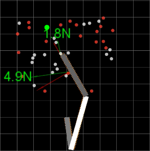
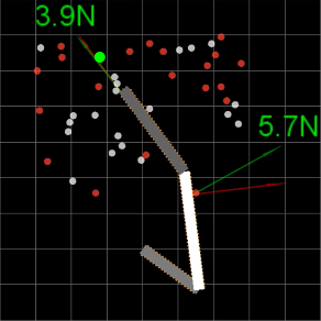
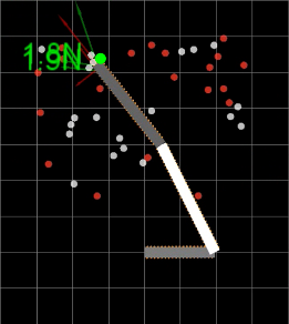
To test the influence of experimentally, we generated 100 trials with 20 fixed and 20 movable obstacles. We then ran the model predictive controller with five different force thresholds on these 100 trials, and recorded all the contact forces every 10ms (at 100Hz). We used the same value for for each contact. Fig. 10 shows the simulated robot successfully reaching to the goal location for one of these trials.
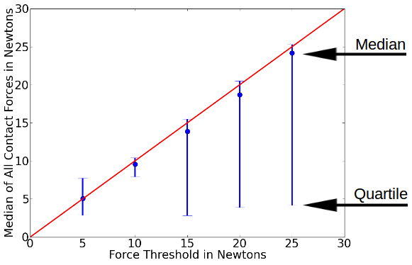
Fig. 11 shows the median and first and fourth quartile of all contact force magnitudes over the 100 trials for different values of . The correlation coefficient between and the median force was providing evidence that the parameter of our model predictive controller can be used to predictably influence the contact forces.
VI-C Hardware-in-the-loop Skin Simulation Testbed
In this section we present results using a real robot and simulated tactile skin within the hardware-in-the-loop skin simulation testbed, described in Sec. IV-D and Fig. 9.
VI-C1 Online Stiffness Estimation
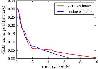
One of the parameters of our model predictive controller is the modeled stiffness at each of the contacts along the arm. This determines how much the robot is willing to move along the contact normal. For example, if the controller’s estimate of the stiffness at a contact is high, it will attempt to push into that contact slowly, since its contact model will predict that a small motion will result in a large increase in the contact force.
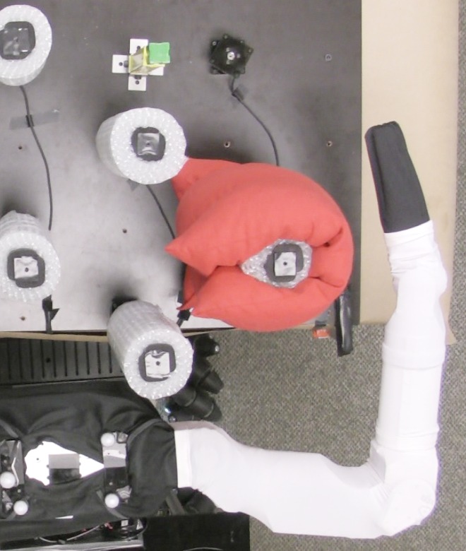
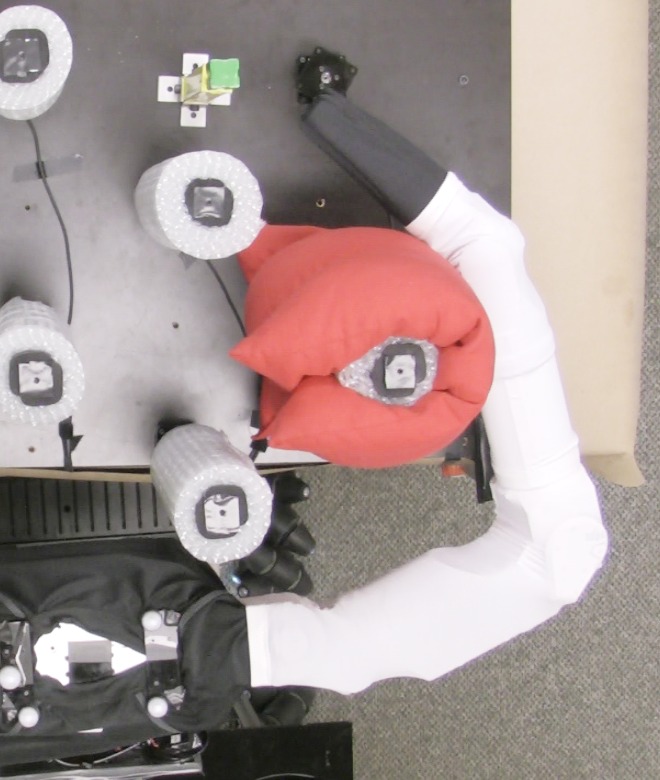
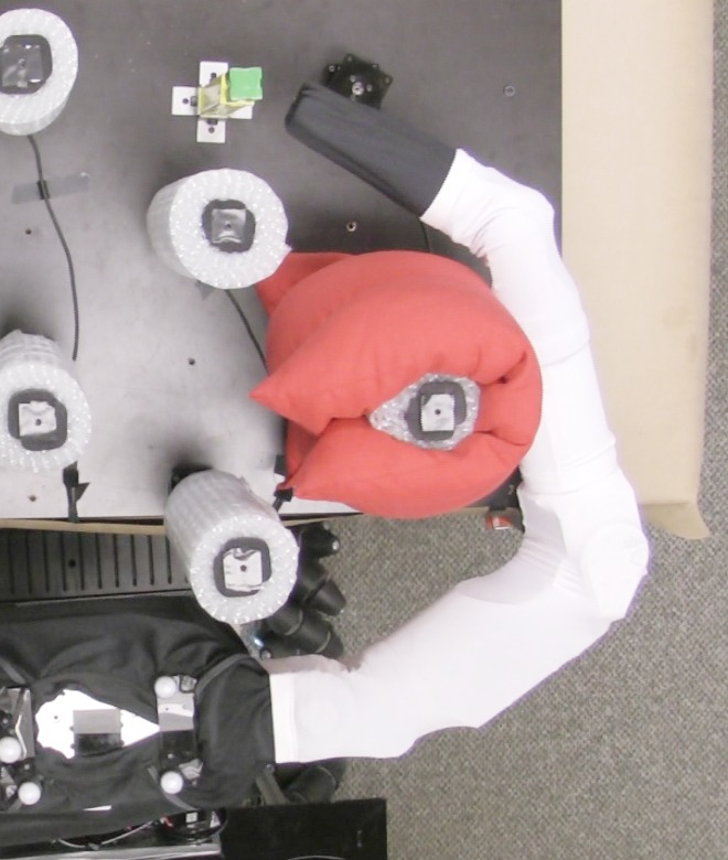
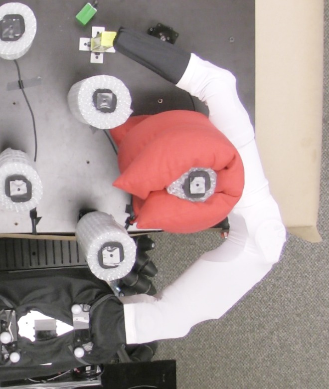
In this section we describe our initial efforts in estimating the stiffness online. We set up an experiment where the robot had to push into a deformable object (pillow) to reach to a goal location, as shown in Fig. 13. We performed two trials. In one trial, the robot used a static and conservative value (high stiffness) for the stiffness at all contact locations. In the second trial, the robot started with the same conservative estimates, but then estimated the stiffness online while interacting with the pillow. Fig. 12 shows that when the robot updated its estimate of the stiffness, it was able to push into the pillow more aggressively and reach the goal location faster than when the stiffness value was a conservative static value.
To estimate the stiffness, we used a history of contact locations and contact forces as returned by the simulated tactile skin. We estimated the stiffness along the current contact normal as the slope of the line (fit using least squares) that describes the change in the normal component of the force with motion of the contact location along the contact normal.
A video of this experiment is part of the supplementary materials.
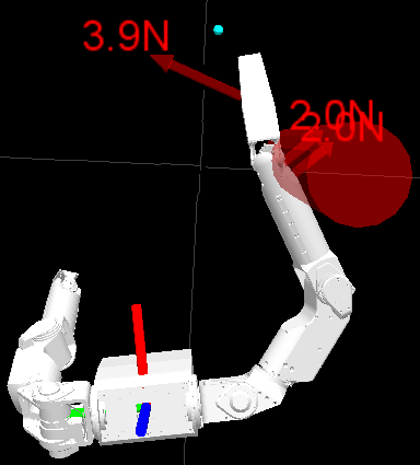
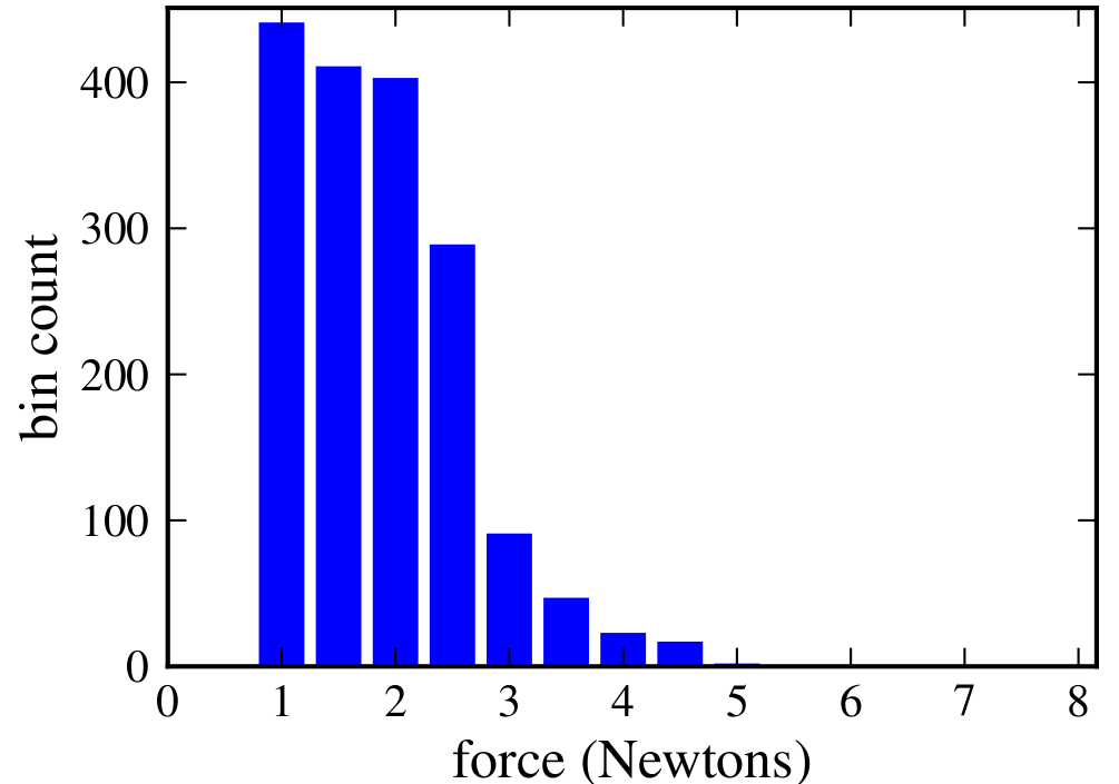
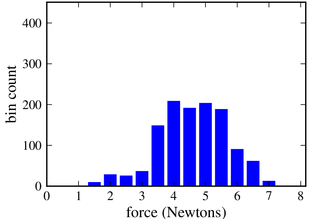
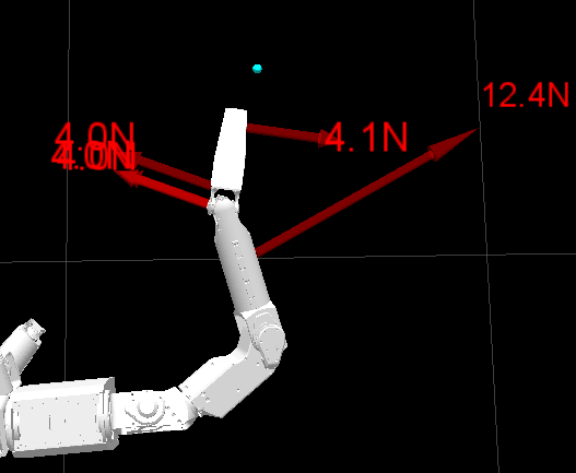
VI-C2 Selective Control of Force Applied to Different Regions in the Environment
With this experiment, we illustrate that the model predictive controller can be used to selectively control the contact force in different regions. We defined a cylindrical volume in the world as ‘fragile’. If the location of a contact in the world frame was within the ‘fragile’ volume, we set the don’t care force threshold, , to . For contacts outside this volume, we set it to . is used in the inequality constraints of Eq. 17.
Fig. 14 shows the forces that the robot applied to the environment during this trial. The histograms of contact forces within and outside the ‘fragile’ region show that the model predictive controller was able to selectively control the force that it applied to different regions in the environment.
VI-C3 Model Predictive Controller vs Baseline Controller
| MPC | Baseline Controller | |
|---|---|---|
| Success rate | 5/5 | 3/5 |
| Avg. max. contact force | 5.6N | 17.7N |
| Avg. contact force above | 5.5N | 14.3N |
| (5N) |
We performed five trials with the goal location in different positions within the hardware-in-the-loop testbed, as shown in Fig. 15. In each trial, the robot moved its mobile base to up to three positions equally spaced along a line and facing the instrumented obstacles, and then attempted to reach to the goal location from a constant pre-determined arm configuration using the model predictive controller. The robot successfully reached each of the five goal locations from one of the three positions. We set the don’t care force threshold, , to and the safety force threshold to for each contact.
As mentioned in Sec. VI-A, we have an additional control layer above the model predictive controller and the baseline controller. This enables the robot to exhibit behavior such as retrying a greedy reach from the left or right of a contact location. A video of these five trials with MPC and the additional control layer is part of the supplementary materials.
For each goal location, we ran the baseline controller with the initial arm configuration and base position from which the model predictive controller was successful. Table II shows the results from the five trials. The baseline controller failed in two out of five trials and resulted in the arm applying larger forces on the environment. The mean contact force (including the don’t care interval of ) was for the model predictive controller and for the baseline controller.
VI-D Forearm Tactile Skin Sensor
In this section we describe results from our experiments with the forearm tactile skin sensor, described in Sec. IV-C and Fig. 8. Since the skin sensor currently covers only the forearm of the robot, we restricted our experiments to not have contacts on the elbow and upper arm of the robot.
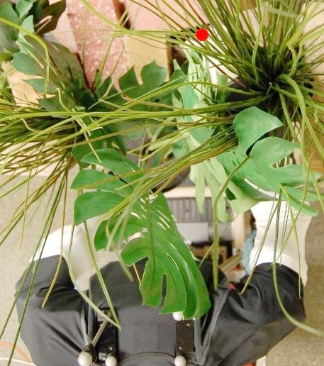
Our simulated foliage is representative of foliage found in nature. It consists of both compliant objects (plastic leaves) and rigid and fixed objects (blocks of wood). The leaves can result in a lot of occlusion for conventional line of sight sensors. Furthermore, the leaves can often be pushed aside with relatively low force but the blocks of wood can not.
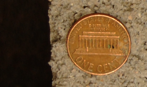
The cinder block is a rigid, heavy, and fixed object, representative of some of the objects a robot would encounter in rubble. The diameter of the robot’s forearm () is close to the size of the opening of the cinder block (). Additionally, the edges are sharp and the surface is abrasive as illustrated in Fig. 16.
VI-D1 Illustrative Examples – Foliage and Cinder Block
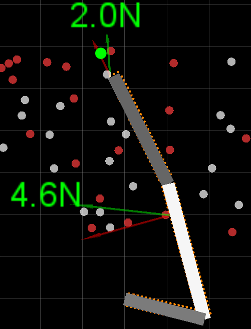
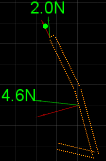
We performed one trial each of the robot reaching to a goal location in foliage and reaching through the opening of a cinder block. Fig. 19 shows two images and the histograms of the contact forces for these two trials. Videos of these two trials are part of the supplementary materials.
VI-D2 Model Predictive Controller vs Baseline Controller in Foliage
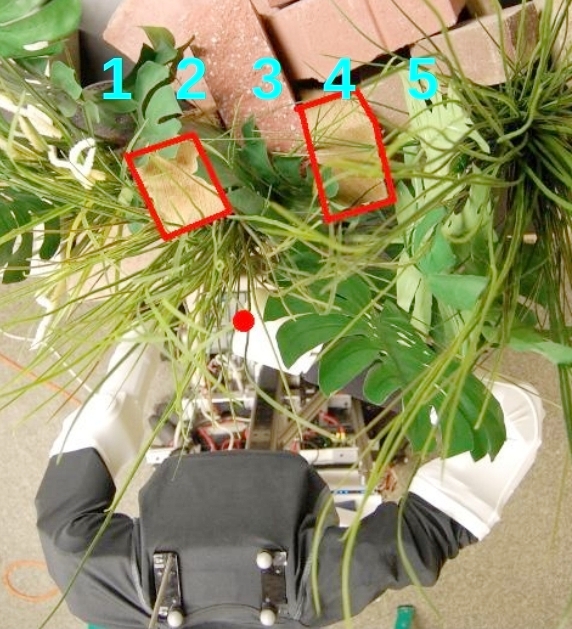
For a more careful evaluation of the model predictive controller and the baseline controller in realistic conditions using the forearm tactile skin sensor, we performed five trials with automatically generated goal locations that were equally spaced along a line within our simulated foliage, as shown in Fig. 17.
We started each trial by positioning the robot at the same location in front of the clutter. The robot then autonomously moved its mobile base to four roughly equally spaced positions along a line, and attempted to reach to the goal location using both the model predictive controller and the baseline controller, as described in Fig. 18.
| MPC | Baseline Controller | |
|---|---|---|
| Success rate | 3/5 | 1/5 |
| Exceeded safety threshold (15N) | 0/20 attempts | 19/20 attempts |
| Avg. max. contact force | 5.5N | 14.5N |
| Avg. contact force above | 5.2N | 9.2N |
| (5N) |
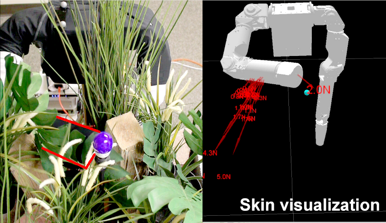
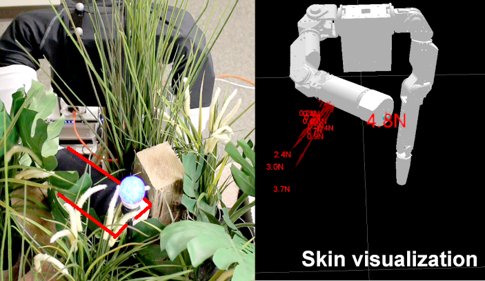
The goal location is vertically below the blue bulb, and is the cyan circle in the skin visualization.
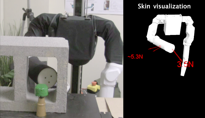
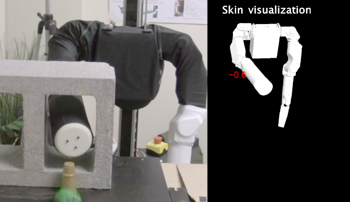
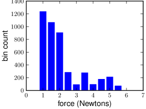
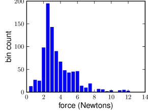
Table III shows the results from a total of twenty reach attempts for each controller from the five trials. The model predictive controller successfully reached goal locations 1, 3, and 5, while the baseline controller was only successful for goal location 5. Further, the model predictive controller successfully kept the contact forces around the don’t care force threshold, , of . In contrast, the baseline controller exceeded the safety force threshold, , of , 19 out of 20 times. The mean contact force (including the don’t care interval of ) was for the model predictive controller and for the baseline controller.
A video of these five trials is part of the supplementary materials.
VII Discussion
Within this section, we discuss broader implications of our research, future work, and current limitations.
VII-A The Big Picture
Our results suggest that our approach is well-matched to manipulation in real-world, high-clutter environments, although further evaluation is required. There are also several broader implications of our work, which we now discuss.
VII-A1 Greedy Control
The performance of our system suggests that greedy feedback control can perform well in practice and that detailed models of the environment and long time horizon planning may not be necessary to achieve high performance. This is similar in spirit to some research on bipedal walking described in Byl and Tedrake (2008).
From our perspective, if empirical research with real robots continues to support this conjecture, it would be a welcome outcome. If one considers the complexity associated with natural environments, such as swamps, rainforests, and caves, a requirement for detailed models and long time horizon planning seems extremely daunting, if not infeasible. Fluids, gasses, granular media, biological materials, and active agents are just a few of the complex contents found across the earth. That biological organisms of all shapes and sizes regularly perform impressive feats of manipulation in these environments demonstrates that the problems are not intractable and that biology has found solutions worthy of emulation. Compliant actuation and whole-body tactile sensing combined with a willingness to make contact with the unknown may be important characteristics of the biological solution to manipulation.
VII-A2 Reaching into the Unknown
Our results also suggest that reaching into the unknown can be a reasonable action for robots with compliant joints and whole-body tactile sensing. As more robots with these underlying capabilities emerge, the value of these attributes should become clearer, especially given the current rarity of whole-body tactile sensing. So far, we have demonstrated the feasibility of haptically reaching into grass-like vegetation with hidden wooden objects, into a constrained massive cinder block with coarse and sharp edges, and into a field of rigid posts covered with compliant materials. In these experiments, both the robot and the environment were unscathed in spite of repeated reaches without explicit foreknowledge of the environments’ contents. Demonstrating success with more diverse environments, real natural environments, real tactile sensing across the entire robot arm, and higher usable degrees of freedom will be important future work.
VII-A3 Human Environments
Within this paper, we have frequently referred to natural high-clutter outdoor environments, such as foliage, in part because of our biological inspiration. However, we expect that our approach and methods would also be beneficial to manipulation in everyday human environments. Humans often encounter high clutter, such as collections of objects on top of tables and shelves, and inside drawers and other containers. Humans also reach into constrained volumes, such as when retrieving objects from under furniture, cleaning hard to reach areas, or performing maintenance on machinery. We would expect service robots to benefit from comparable capabilities. Assistive robots might also benefit from our approach, since humans often make contact with their arms and other parts of their body when providing physical assistance to other people, such as when helping someone get out of bed.
VII-A4 Emergent Intelligence
Although our low-level controller is greedy and has been provided waypoints that are always along a straight line from the end effector’s current position to the goal location, to us the resulting qualitative motion of the robot’s arm appears to be intelligent, complex, and lifelike. To objectively support these notions would likely require human-robot interaction studies, so they must be treated skeptically. Nonetheless, like Herbert Simon’s ant walking on the beach (Simon, 1996), the robot’s reactions to the complexity of the world result in complex emergent motion. For example, due to tactile sensing and the controller, the robot can move against a compliant object until the force is higher than desired and then pivot around it. Maneuvers such as this appear to be sensible, even though they are not the result of explicitly planned trajectories. Likewise, the robot can easily respond to dynamic elements of the environment, since it regenerates a model at each time step based on its tactile sensing and greedily decides how to move. Our approach and results relate strongly to behavior-based robotics (Brooks, 1991).
VII-B Future Work
The controller we have presented has promising performance and its properties serve to illustrate our overall approach. Many opportunities exist to integrate this controller, or similar controllers, into manipulation systems. We have presented results with reactive behaviors, but we would expect the controller to also be appropriate for the execution of planned trajectories or commands from a teleoperator. Due to the greedy controller and the potential for local minima, some form of higher level control is required. Our approach has been to develop higher level controllers that detect when the arm has stopped making progress (reached a local minimum), and then restart the controller with new initial conditions. How to best design complementary higher level controllers and associated representations with memory merits further inquiry.
There are also numerous avenues that remain open for further development and evaluation of this controller and similar controllers. For example, we have fixed the stiffness of the robot’s joints to low constant values, which could instead be varied at each time step. A related open question is how to initialize and adapt the various controller parameters given a robot, an environment, and a task. Data-driven methods from machine learning might be a worthwhile direction for research related to this question.
VII-C Limitations
In spite of its good performance in our experiments, the current controller does have limitations that could motivate revisions of this controller, or new controllers entirely. First, our contact model consists of a linear spring, which is computationally favorable, but predicts adhesive forces when breaking contact. Second, the controller places no penalty on a predicted contact force that is less than , and has a hard inequality constraint that prevents higher predicted forces. Yet in practice, the actual contact forces sometimes exceed this constraint. Currently, the controller handles this by removing the constraint and adding a quadratic penalty, which results in an objective function that varies over time. It may be advantageous to instead use a constant objective function that is smooth, hence softening the constraint.
Third, the current controller ignores dynamics. The resulting quasi-static model is well-matched to slow motions. And, slow motions are reasonable when performing haptically-guided manipulation without a model in high clutter, since a collision could occur at any moment. Nonetheless, taking dynamics into account might enable the controller to attain better performance at higher speeds, and better control of the arm’s velocity. Fourth, so far, we have only tested the controller for achieving a position of the end effector. Objectives such as an arm posture or full pose of the end effector would be better matched to some tasks. These and other objectives could plausibly be represented as quadratic objective functions, but we have not tested this possibility.
VIII Conclusion
We have presented our approach to manipulation, which from the outset emphasizes contact with the world. We assume that low contact forces are benign, and focus on the development of robotic systems that can control their contact forces during goal-directed motion. Inspired by biology, we assume that the robot has low-stiffness compliant actuation at its joints, and tactile sensing across its entire surface.
We then described a novel controller that exploits these assumptions. The controller only requires haptic sensing and does not need a detailed model of the environment prior to contact. It also explicitly allows multiple contacts across the entire surface of the arm.
The controller uses model predictive control (MPC) with a time horizon of length one, and a linear quasi-static model. As quantitatively summarized in the following list, we have empirically shown that our MPC controller enables a variety of robots to haptically reach goal locations in highly cluttered environments with low contact forces, and that it outperforms a baseline controller that uses the same low-stiffness actuation at its joints.
-
1.
Successfully enables a simulated robot to reach to a location in clutter: In an experiment with 2420 trials, our MPC controller succeeded in 150% more trials than our baseline controller, and had lower average contact forces ( vs. ). Even though it is a greedy controller, it was within 8% of optimal performance when allowed to make up to 6 reach attempts. In another experiment, the correlation between the MPC controller’s don’t care force threshold and the median applied force was 0.998, which indicates that this controller parameter predictably influences the contact forces applied by the arm.
-
2.
Successfully enables a real robot with simulated skin to reach to a location in clutter: Using the MPC controller, our robot autonomously reached 5 human specified targets, while the baseline controller only reached 3. The MPC controller had lower average maximum force for reach attempts ( vs. for baseline). In addition, we demonstrated that the robot can apply less force to a designated fragile region, and can estimate that a contact has low stiffness online resulting in more aggressive and efficient progress to a goal location.
-
3.
Successfully enables a real robot with real skin to reach to a location in real clutter: We performed a fully autonomous evaluation of our MPC controller in which it successfully commanded the real robot with real forearm skin to reach 3 out of 5 automatically generated target locations within foliage (target locations were not necessarily achievable and could be embedded within rigid objects). The baseline controller succeeded in reaching 1 out of 5 of these targets from the same starting conditions as the MPC controller. The MPC controller also achieved lower average maximum force than the baseline controller ( vs. ), which corresponds to the MPC controller’s don’t care force threshold of .
The MPC controller also enabled the robot to reach into a cinder block representative of rubble, which demonstrates the feasibility of moving against rigid, sharp and coarse materials, and through constrained passages.
IX Supplementary Materials
IX-1 Videos
We have prepared the following videos as part of the supplementary materials:
-
•
Model predictive controller vs baseline controller within the hardware-in-the-loop testbed as described in Sec. VI-C3.
-
•
Online stiffness estimation with the hardware-in-the-loop testbed as described in Sec. VI-C1.
-
•
Illustrative examples of reaching in foliage and through the opening of a cinder block using the real forearm tactile skin sensor, described in Sec. VI-D1.
-
•
Model predictive controller vs baseline controller in foliage using the forearm tactile skin sensor, as described in Sec. VI-D2.
-
•
Video showing the “simple” impedance controller and low stiffness at the joints for the robot Cody.
-
•
The simulated robot reaching to the goal location in one of the trials with the software simulation testbed described in Sec. VI-B2.
IX-2 Code
If accepted for publication, we will release our code as open source. We will also provide instructions and data to reproduce the results within the software simulation testbed (Sec. VI-B).
X Acknowledgements
We gratefully acknowledge support from DARPA Maximum Mobility and Manipulation (M3) Contract W911NF-11-1-603. This work benefitted from discussions with Magnus B. Egerstedt, Harvey Lipkin, Mike Stilman, and James M. Rehg.
We thank Mark Cutkosky and the Stanford Biomimetics and Dexterous Manipulation Lab for their contributions to the forearm tactile skin sensor.
We also thank Jeff Weber, Andy Metzger, Benjamin Valenti, Pierre-Luc Bacon, Robert Kelbley, and John Ulmen for their contributions to the forearm tactile skin sensor hardware and software.
References
- Abbeel et al (2010) Abbeel P, Coates A, Ng A (2010) Autonomous helicopter aerobatics through apprenticeship learning. The International Journal of Robotics Research
- Albu-Schaffer et al (2003) Albu-Schaffer A, Ott C, Frese U, Hirzinger G (2003) Cartesian impedance control of redundant robots: Recent results with the dlr-light-weight-arms. In: Robotics and Automation, 2003. Proceedings. ICRA’03. IEEE International Conference on, IEEE, vol 3, pp 3704–3709
- Alexander (1990) Alexander R (1990) Three uses for springs in legged locomotion. The International Journal of Robotics Research
- Bellingham et al (2002) Bellingham J, Richards A, How J (2002) Receding horizon control of autonomous aerial vehicles. In: American Control Conference
- Bianchi (2007) Bianchi L (2007) Mechanotransduction: Touch and feel at the molecular level as modeled in caenorhabditis elegans. Molecular Neurobiology 36(3):254–271
- Bicchi (1993) Bicchi A (1993) Force distribution in multiple whole-limb manipulation. In: IEEE International Conference on Robotics and Automation
- Bicchi and Kumar (2000) Bicchi A, Kumar V (2000) Robotic grasping and contact: A review. In: IEEE International Conference on Robotics and Automation.
- Bicchi et al (1993) Bicchi A, Salisbury J, Brock D (1993) Contact sensing from force measurements. The International Journal of Robotics Research
- Boyd and Vandenberghe (2004) Boyd S, Vandenberghe L (2004) Convex optimization. Cambridge Univ Pr
- Brooks (1991) Brooks R (1991) Intelligence without reason. Artificial intelligence: critical concepts
- Buerger (2006) Buerger S (2006) Stable, High-Force, Low-Impedance Robotic Actuators for Human-Interactive Machines. PhD thesis, MIT
- Buerger and Hogan (2007) Buerger S, Hogan N (2007) Complementary stability and loop shaping for improved human–robot interaction. IEEE Transactions on Robotics 23(2):232–244
- Byl and Tedrake (2008) Byl K, Tedrake R (2008) Approximate optimal control of the compass gait on rough terrain. In: IEEE International Conference on Robotics and Automation
- Catania (1999) Catania K (1999) A nose that looks like a hand and acts like an eye: the unusual mechanosensory system of the star-nosed mole. Journal of Comparative Physiology A: Neuroethology, Sensory, Neural, and Behavioral Physiology
- De Schutter et al (1999) De Schutter J, Bruyninckx H, Dutré S, De Geeter J, Katupitiya J, Demey S, Lefebvre T (1999) Estimating first-order geometric parameters and monitoring contact transitions during force-controlled compliant motion. The International Journal of Robotics Research
- Diankov and Kuffner (2008) Diankov R, Kuffner J (2008) Openrave: A planning architecture for autonomous robotics. Robotics Institute, Pittsburgh, PA, Tech Rep CMU-RI-TR-08-34
- Dogar and Srinivasa (2011) Dogar M, Srinivasa S (2011) A framework for push-grasping in clutter. Robotics: Science and Systems
- Dogar et al (2010) Dogar M, Hemrajani V, Leeds D, Kane B, Srinivasa S (2010) Proprioceptive Localization for Mobile Manipulators. Tech. rep., Carnegie Mellon University
- Dominy (2004) Dominy N (2004) Fruits, fingers, and fermentation: the sensory cues available to foraging primates. Integrative and Comparative Biology
- Eberman (1989) Eberman B (1989) Whole-arm manipulation: kinematics and control. Master’s thesis, MIT
- Eberman and Salisbury (1990) Eberman B, Salisbury J (1990) Determination of manipulator contact information from joint torque measurements. In: Experimental Robotics I
- Edsinger and Kemp (2007a) Edsinger A, Kemp CC (2007a) Human-robot interaction for cooperative manipulation: Handing objects to one another. In: Proceedings of the 16th IEEE International Symposium on Robot and Human Interactive Communication (RO-MAN)
- Edsinger and Kemp (2007b) Edsinger A, Kemp CC (2007b) Two arms are better than one: A behavior-based control system for assistive bimanual manipulation. In: Proceedings of the 13th International Conference on Advanced Robotics (ICAR)
- Erez et al (2011) Erez T, Tassa Y, Todorov E (2011) Infinite-horizon model predictive control for periodic tasks with contacts. In: Robotics: Science and Systems (RSS)
- Escande and Kheddar (2009) Escande A, Kheddar A (2009) Contact planning for acyclic motion with tasks constraints. In: IEEE/RSJ International Conference on Intelligent Robots and Systems (IROS)
- Featherstone and Orin (2008) Featherstone R, Orin DE (2008) Chapter 2: Dynamics, Handbook of Robotics, Siciliano, Bruno; Khatib, Oussama (Eds.). Springer
- Frank et al (2011) Frank B, Stachniss C, Abdo N, Burgard W (2011) Using gaussian process regression for efficient motion planning in environments with deformable objects. In: Workshops at the Twenty-Fifth AAAI Conference on Artificial Intelligence
- From et al (2011) From P, Gravdahl J, Lillehagen T, Abbeel P (2011) Motion planning and control of robotic manipulators on seaborne platforms. Control engineering practice
- Garcia et al (1989) Garcia C, Prett D, Morari M (1989) Model predictive control: Theory and practice–a survey. Automatica
- Garcia et al (1998) Garcia M, Chatterjee A, Ruina A, Coleman M (1998) The simplest walking model: Stability, complexity, and scaling. Journal of Biomechanical Engineering
- Goodman (2006) Goodman MB (2006) WormBook, chap Mechanosensation. DOI 10.1895/wormbook.1.7.1, URL http://www.wormbook.org/
- Gu and Ballard (2006) Gu X, Ballard D (2006) An equilibrium point based model unifying movement control in humanoids. In: RSS
- Hauser et al (2005) Hauser K, Bretl T, Latombe J (2005) Non-gaited humanoid locomotion planning. In: Humanoids
- Hersch and Billard (2006) Hersch M, Billard A (2006) A biologically-inspired controller for reaching movements. In: IEEE/RAS-EMBS International Conference on Biomedical Robotics and Biomechatronics (BIOROB)
- Hogan (1984) Hogan N (1984) Adaptive control of mechanical impedance by coactivation of antagonist muscles. IEEE Transactions on Automatic Control
- Hogan (1988) Hogan N (1988) On the stability of manipulators performing contact tasks. Robotics and Automation, IEEE Journal of 4(6):677–686
- Hogan and Buerger (2005) Hogan N, Buerger S (2005) Impedance and Interaction Control, Robotics and Automation Handbook, chap 19
- Hsiao and Lozano-Perez (2006) Hsiao K, Lozano-Perez T (2006) Imitation learning of whole-body grasps. In: IEEE/RSJ International Conference on Intelligent Robots and Systems
- Hsiao et al (2010) Hsiao K, Chitta S, Ciocarlie M, Jones E (2010) Contact-reactive grasping of objects with partial shape information. In: IEEE/RSJ International Conference on Intelligent Robots and Systems (IROS)
- Ivaldi et al (2010) Ivaldi S, Fumagalli M, Nori F, Baglietto M, Metta G, Sandini G (2010) Approximate optimal control for reaching and trajectory planning in a humanoid robot. In: IEEE/RSJ International Conference on Intelligent Robots and Systems (IROS)
- Iwaniuk and Whishaw (1999) Iwaniuk A, Whishaw I (1999) How skilled are the skilled limb movements of the raccoon (procyon lotor)? Behavioural brain research 99(1):35–44
- J. Pratt and Pratt (2001) J Pratt PD M Chew, Pratt G (2001) Virtual Model Control: An intuitive approach for bipedal locomotion. International Journal of Robotics Research 20(2):129–143
- Jain and Kemp (2009a) Jain A, Kemp CC (2009a) Behavior-based door opening with equilibrium point control. In: RSS Workshop: Mobile Manipulation in Human Environments
- Jain and Kemp (2009b) Jain A, Kemp CC (2009b) Pulling Open Novel Doors and Drawers with Equilibrium Point Control. In: Humanoids
- Jain and Kemp (2010a) Jain A, Kemp CC (2010a) EL-E: An Assistive Mobile Manipulator that Autonomously Fetches Objects from Flat Surfaces. Autonomous Robots
- Jain and Kemp (2010b) Jain A, Kemp CC (2010b) Pulling Open Doors and Drawers: Coordinating an Omni-directional Base and a Compliant Arm with Equilibrium Point Control. In: ICRA
- Johansson and Flanagan (2009) Johansson R, Flanagan J (2009) Coding and use of tactile signals from the fingertips in object manipulation tasks. Nature Reviews Neuroscience 10(5):345–359
- Johnson and Johnson (1987) Johnson K, Johnson K (1987) Normal Contact of Elastic Solids: Hertz Theory, Contact Mechanics, chap 4
- Kaneko and Tanie (1994) Kaneko M, Tanie K (1994) Contact point detection for grasping an unknown object using self-posture changeability. IEEE Transactions on Robotics and Automation
- Kao et al (2008) Kao I, Lynch K, Burdick JW (2008) Contact Modeling and Manipulation, Springer Handbook of Robotics, chap 27
- Kavraki and LaValle (2008) Kavraki LE, LaValle SM (2008) Chapter 5: Motion Planning, Handbook of Robotics, Siciliano, Bruno; Khatib, Oussama (Eds.). Springer
- Khatib (1987) Khatib O (1987) A unified approach for motion and force control of robot manipulators: The operational space formulation. IEEE Journal of Robotics and Automation
- Killpack et al (2010) Killpack M, Deyle T, Anderson C, Kemp C (2010) Visual odometry and control for an omnidirectional mobile robot with a downward-facing camera. In: IEEE/RSJ International Conference on Intelligent Robots and Systems
- Kim and Streit (1995) Kim H, Streit D (1995) Configuration dependent stiffness of the puma 560 manipulator: analytical and experimental results. Mechanism and machine theory
- Kroshko (2011) Kroshko DL (2011) Openopt framework. URL http://openopt.org
- Kulchenko and Todorov (2011) Kulchenko P, Todorov E (2011) First-exit model predictive control of fast discontinuous dynamics: Application to ball bouncing. In: IEEE International Conference on Robotics and Automation (ICRA)
- LaValle and Kuffner (2001) LaValle S, Kuffner J (2001) Randomized kinodynamic planning. The International Journal of Robotics Research 20(5):378
- Lederman and Klatzky (2009) Lederman SJ, Klatzky RL (2009) Haptic perception: A tutorial. Attention, Perception and Psychophysics (71):1439–1459
- Leeper et al (2012) Leeper A, Hsiao K, Ciocarlie M, Takayama L, Gossow D (2012) Strategies for human-in-the-loop robotic grasping. In: ACM/IEEE international conference on Human Robot Interaction – To Appear
- Legagne et al (2011) Legagne S, Kheddar A, Yoshida E (2011) Generation of Optimal Dynamic Multi-Contact Motions : Application to Humanoid Robots. IEEE Transactions on Robotics – under review
- Lozano-Perez (1987) Lozano-Perez T (1987) A simple motion-planning algorithm for general robot manipulators. IEEE Transactions on Robotics and Automation
- Lumpkin et al (2010) Lumpkin EA, Marshall KL, Nelson AM (2010) The cell biology of touch. Journal of Cell Biology 191(2):237–248, DOI 10.1083/jcb.201006074
- Maladen et al (2010) Maladen R, Ding Y, Umbanhowar P, Kamor A, Goldman D (2010) Biophysically inspired development of a sand-swimming robot. Robotics: Science and Systems (RSS)
- Manchester et al (2011) Manchester I, Mettin U, Iida F, Tedrake R (2011) Stable dynamic walking over uneven terrain. The International Journal of Robotics Research
- Mason et al (2011) Mason M, Rodriguez A, Srinivasa S, Vazquez A (2011) Autonomous manipulation with a general-purpose simple hand. International Journal of Robotics Research
- McKenna et al (2008) McKenna J, Anhalt D, Bronson F, Brown H, Schwerin M, Shammas E, Choset H (2008) Toroidal skin drive for snake robot locomotion. In: International Conference on Robotics and Automation
- Metta et al (2011) Metta G, Natale L, Nori F, Sandini G (2011) Force control and reaching movements on the icub humanoid robot. International Symposium on Robotics Research
- Migliore (2009) Migliore S (2009) The Role of Passive Joint Stiffness and Active Knee Control in Robotic Leg Swinging: Applications to Dynamic Walking. PhD thesis, Georgia Institute of Technology
- Migliore et al (2005) Migliore S, Brown E, DeWeerth S (2005) Biologically inspired joint stiffness control. In: IEEE International Conference on Robotics and Automation
- Morari and Lee (1999) Morari M, Lee JH (1999) Model predictive control: past, present and future. Computers & Chemical Engineering 23(4-5):667–682
- Natale and Torres-Jara (2006) Natale L, Torres-Jara E (2006) A sensitive approach to grasping. In: International Workshop on Epigenetic Robotics
- Ott et al (2007) Ott C, Baeuml B, Borst C, Hirzinger G (2007) Autonomous opening of a door with a mobile manipulator: A case study. IFAC Symposium on Intelligent Autonomous Vehicles
- Park and Khatib (2008) Park J, Khatib O (2008) Robot multiple contact control. Robotica 26(5)
- Pastor et al (2011) Pastor P, Righetti L, Kalakrishnan M, Schaal S (2011) Online movement adaptation based on previous sensor experiences. In: IROS
- Patil et al (2011) Patil S, van den Berg J, Alterovitz R (2011) Motion planning under uncertainty in highly deformable environments. In: Robotics: Science and Systems (RSS)
- Petrovskaya et al (2007) Petrovskaya A, Park J, Khatib O (2007) Probabilistic Estimation of Whole Body Contacts for Multi-Contact Robot Control. IEEE International Conference on Robotics and Automation
- Platt Jr et al (2003) Platt Jr R, Fagg A, Grupen R (2003) Extending fingertip grasping to whole body grasping. In: IEEE International Conference on Robotics and Automation
- Pratt (2002) Pratt G (2002) Low impedance walking robots 1. Integrative and Comparative Biology 42(1):174–181
- Pratt and Williamson (1995) Pratt G, Williamson M (1995) Series elastic actuators. In: IROS
- Quigley et al (2009) Quigley M, Gerkey B, Conley K, Faust J, Foote T, Leibs J, Eric Berger RW, Ng A (2009) ROS: An Open-Source Robot Operating System. In: ICRA Open-Source Software workshop
- Raibert and Craig (1981) Raibert M, Craig J (1981) Hybrid position/force control of manipulators. Journal of Dynamic Systems, Measurement, and Control 102(127):126–133
- Raibert et al (2008) Raibert M, Blankespoor K, Nelson G, Playter R, et al (2008) Bigdog, the rough–terrain quadruped robot. In: Proceedings of the 17th World Congress
- Rodriguez et al (2006) Rodriguez S, Lien J, Amato N (2006) Planning motion in completely deformable environments. In: IEEE International Conference on Robotics and Automation
- Romano et al (2011) Romano J, Hsiao K, Niemeyer G, Chitta S, Kuchenbecker K (2011) Human-inspired robotic grasp control with tactile sensing. IEEE Transactions on Robotics
- Salisbury (1984) Salisbury J J (1984) Interpretation of contact geometries from force measurements. In: ICRA, vol 1
- Saranli et al (2001) Saranli U, Buehler M, Koditschek D (2001) Rhex: A simple and highly mobile hexapod robot. The International Journal of Robotics Research
- Saxena et al (2008) Saxena A, Driemeyer J, Ng A (2008) Robotic Grasping of Novel Objects using Vision. The International Journal of Robotics Research 27(2):157
- Sentis and Khatib (2005) Sentis L, Khatib O (2005) Synthesis of whole-body behaviors through hierarchical control of behavioral primitives. International Journal of Humanoid Robotics
- Sentis et al (2010) Sentis L, Park J, Khatib O (2010) Compliant Control of Multicontact and Center-of-Mass Behaviors in Humanoid Robots. IEEE Transactions on Robotics 26(3)
- Shadmehr (1993) Shadmehr R (1993) Control of equilibrium position and stiffness through postural modules. Journal of motor behavior
- Simon (1996) Simon H (1996) The sciences of the artificial. the MIT Press
- Sims Jr et al (1988) Sims Jr D, Cavanagh P, Ulbrecht J (1988) Risk factors in the diabetic foot. Physical Therapy
- Smith et al (2011) Smith R, et al (2011) Open dynamics engine. URL http://www.ode.org
- Srinivasa et al (2009) Srinivasa S, Ferguson C D Helfrich, Berenson D, Collet A, Diankov R, Gallagher G, Hollinger G, Kuffner J, VandeWeghe M (2009) Herb: A Home Exploring Robotic Butler. Autonomous Robots
- Stilman et al (2007) Stilman M, Schamburek J, Kuffner J, Asfour T (2007) Manipulation planning among movable obstacles. In: IEEE Int. Conf. on Robotics and Automation
- Stulp et al (2009) Stulp F, Kresse I, Maldonado A, Ruiz F, Fedrizzi A, Beetz M (2009) Compact models of human reaching motions for robotic control in everyday manipulation tasks. In: IEEE International Conference on Development and Learning
- Ulmen et al (2012) Ulmen J, Edsinger A, Cutkosky M (2012) A highly sensitive, manufacturable, low-cost tactile sensor for responsive robots. In: In Submission, IEEE International Conference on Robotics and Automation.
- webpage (2011a) webpage (2011a) URL http://www.nativeamerica.com/research.html
- webpage (2011b) webpage (2011b) URL http://wildshores.blogspot.com/2009/06/wild-monkeys-at-breakfast-in-admiralty.html
- webpage (2011c) webpage (2011c) URL http://www.ethantw.com/noodling.html,http://en.wikipedia.org/wiki/Noodling
- Wieber (2006) Wieber P (2006) Trajectory free linear model predictive control for stable walking in the presence of strong perturbations. In: IEEE-RAS International Conference on Humanoid Robots
- Williamson (1996) Williamson M (1996) Postural primitives: Interactive behavior for a humanoid robot arm. In: Proceedings of the Fourth International Conference on Simulation of Adaptive Behavior
- Williamson (1999) Williamson M (1999) Robot arm control exploiting natural dynamics. PhD thesis, Massachusetts Institute of Technology