Quantitative study of the spin Hall magnetoresistance in ferromagnetic insulator/normal metal hybrids
Abstract
We experimentally investigate and quantitatively analyze the spin Hall magnetoresistance effect in ferromagnetic insulator/platinum and ferromagnetic insulator/nonferromagnetic metal/platinum hybrid structures. For the ferromagnetic insulator we use either yttrium iron garnet, nickel ferrite or magnetite and for the nonferromagnet copper or gold. The spin Hall magnetoresistance effect is theoretically ascribed to the combined action of spin Hall and inverse spin Hall effect in the platinum metal top layer. It therefore should characteristically depend upon the orientation of the magnetization in the adjacent ferromagnet, and prevail even if an additional, nonferromagnetic metal layer is inserted between Pt and the ferromagnet. Our experimental data corroborate these theoretical conjectures. Using the spin Hall magnetoresistance theory to analyze our data, we extract the spin Hall angle and the spin diffusion length in platinum. For a spin mixing conductance of we obtain a spin Hall angle of and a spin diffusion length of for Pt in our thin film samples.
pacs:
72.25.Mk,72.25.Ba,75.47.-mI Introduction
Pure spin currents - which transport only (spin) angular momentum, but no electrical charge - represent a new paradigm for spin transport and spin electronics. In the last few years, two spin current generation methods have evolved: the spin Seebeck effect (SSE) Uchida et al. (2011a); Adachi et al. (2011, 2010); Uchida et al. (2009); Xiao et al. (2010); Uchida et al. (2010a, b, 2008); Jaworski et al. (2010); Uchida et al. (2010c); Jaworski et al. (2011); Le Breton et al. (2011); Slachter et al. (2010); Weiler et al. (2012a) and the spin pumping effect Qiu et al. (2012); Saitoh et al. (2006); Ando et al. (2010a, 2011a, b, 2011b); Hoffmann (2007); Ando and Saitoh (2012); Czeschka et al. (2011); Uchida et al. (2011b); Weiler et al. (2012b); Brataas et al. (2002). Both methods involve ferromagnet (FM)/nonferromagnet (NM) hybrid structures to generate and to detect the spin currents. While originally the focus was on electrically conducting FM/NM heterostructures, ferromagnetic insulators (FMI) are increasingly exploited in FMI/NM hybrids. Kajiwara et al. (2010); Uchida et al. (2010c) FMIs are electrically insulating materials which exhibit long-range magnetic order, such that magnetic excitations (spin currents) can propagate in FMIs, while charge currents cannot. In this sense, FMIs allow to cleanly separate spin current from charge current effects. One of the prototype examples for a FMI compound is yttrium iron garnet (Y3Fe5O12, YIG). Kajiwara et al. (2010); Uchida et al. (2010c); Heinrich et al. (2011)
The interplay between spin and charge transport in FM/NM devices gives rise to interesting physical phenomena. A prominent example is the spin Hall magnetoresistance (SMR) discovered recently in FMI/NM hybrids. Nakayama et al. (2012a); Chen et al. (2013); [Shortlybeforesubmissionofthemanuscript; webecameawareofthispublicationonthearXiv:]vlietstra_spin-hall_2013 The SMR is related to the absorption/reflection of a spin current density flowing along the direction normal to the FMI/NM interface. The spin current is generated by a charge current density in the NM layer via the spin Hall effect (SHE): Dyakonov and Perel (1971); Hirsch (1999)
| (1) |
The total is here the direction of the spin current, while its spin polarization is oriented perpendicular to and . is the spin Hall angle defined by the ratio of the spin Hall conductivity and the electric conductivity [Takahashi and Maekawa, 2008] and is the positive elementary charge. In FMI/NM hybrids, the amount of spin current absorption/reflection by the FMI at the FMI/NM interface depends on the orientation of the FMI magnetization with respect to the polarization of the spin current. The amount of spin current reflected at the interface in turn induces a charge current via the inverse spin Hall effect (ISHE) in the NM layer. The total -orientation dependent spin current flow across the FMI/NM interface represents a dissipation channel for charge transport, and thus affects the resistance of the NM. The resulting spin Hall magnetoresistance of the NM is clearly discernible from a conventional anisotropic magnetoresistance McGuire and Potter (1975) (AMR) type of effect, since the SMR depends on the angle between the magnetization and the spin polarization , while the AMR depends on the angle between and the charge current direction .
Here, we give a detailed, quantitative analysis of the SMR in YIG/Pt, YIG/Au/Pt, and YIG/Cu/Pt samples. We furthermore report the observation of SMR in nickel ferrite (NiFe2O4)/Pt, and magnetite (Fe3O4)/Pt samples. The latter two materials are also important for SSE measurements since recently the SSE was observed in semiconducting NiFe2O4 Meier et al. (2013) and weakly conducting Fe3O4 Ramos et al. (2013).
The paper is organized as follows: First, we explain the SMR effect in a simple phenomenological picture, followed by a quantitative model. Next, we present structural and magnetic data of the YIG/Pt hybrids, in connection with extensive magnetoresistance measurement data as a function of the magnetization orientation . We use our theoretical model to quantitatively analyze the experimental data and thus obtain estimates for the unknown parameters, i.e., the spin Hall angle and spin diffusion length in Pt. Moreover, we verify that the SMR does not originate from a static equilibrium magnetic proximity effect in the non-magnetic Pt layer, since the SMR persists even when a second, diamagnetic NM is inserted between YIG and Pt. Finally, we show that the SMR effect is also observed in FMI/Pt hybrid structures using Fe3O4 or NiFe2O4 as the FMI.
II Theory of the spin Hall magnetoresistance
The SMR effect stems from a combination of the spin Hall effect (SHE), which converts a charge current into a spin current , and the inverse spin Hall (ISHE) effect, where a spin current induces a charge current . Hirsch (1999); Takahashi and Maekawa (2008)
We start with a phenomenological explanation of the SMR effect by discussing the influence of two different boundary conditions on the steady state in case of both the ordinary Hall effect (OHE) and the SHE. Hall (1879)
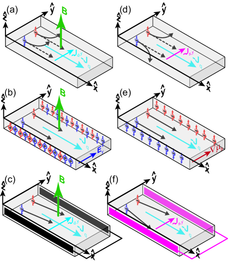
We first consider the OHE in the single band model with a longitudinal charge current density in direction as illustrated in Fig. 1(a). Due to an external magnetic field applied along , the charge carriers experience a Lorentz force in the transverse () direction. In typical Hall effect measurements, the potential drop (voltage) along is recorded at zero current flow along . This corresponds to the boundary condition that the charge carriers can not escape and therefore accumulate on the transverse sides (open circuit condition for charge transport). The resulting charge accumulation leads to a compensating electrical field , which can be detected as a voltage drop over the transverse sides. In the single band model, one finds that the longitudinal resistance is independent of (cf. Fig. 1(b)). Ashcroft and Mermin (1976) In contrast, one may assume the boundary condition that (placing an electrical short between the transverse contacts as illustrated in Fig. 1(c)), such that a transverse current arises, depending on the applied magnetic field magnitude . This effectively reduces . The external current source has to compensate for this effect by increasing the effective longitudinal voltage applied to the sample, such that the charge current and thus stays constant. For this boundary condition, the observed longitudinal resistance thus does depend on the external magnetic field. Ashcroft and Mermin (1976)
We now turn to the SHE illustrated in Fig. 1(d), by which the longitudinal charge current density induces a transverse spin current . Since we are here concerned with the spin current flow across the FMI/NM interface, we can restrict the discussion to along the interface normal . According to Eq.(1), this implies that the spin orientation . The vector thus represents a flow of -polarized spins along . For an open (spin current) circuit boundary condition as illustrated in Fig. 1(e), we obtain a spin accumulation on the transverse sides of the sample. Kato et al. (2004) This spin accumulation leads to a gradient in the spin dependent electrochemical potential , which compensates the spin current generated by the SHE. In the steady state, the longitudinal resistance is thus independent of the SHE, in analogy to the OHE in Fig. 1(b). In contrast, if we consider short-circuited boundary conditions for the spin channel (shorting ) a spin current flows through the lateral faces. The current source driving the charge current again must compensate for this transverse current flow, which results in an increase in the longitudinal resistance. This change in longitudinal resistance is the SMR effect. Dyakonov predicted a magnetoresistance, stemming from the magnetic field-dependent dephasing of a spin accumulation generated by the spin Hall effect at the edges of single NM films. Dyakonov (2007) The spin accumulation at the edges and the corresponding magnetoresistance is negligibly small for extended thin films. In contrast, we consider here the spin accumulations on the surface of the conducting film and modulate them by a FMI rather than an applied magnetic field.
Interestingly, FMI/NM heterostructures allow to gradually switch between open and closed spin current circuit boundary conditions by changing the magnetization orientation in the FMI with respect to . To realize an ideal spin current short circuit condition as depicted in Fig. 1(f), FMI/NM/FMI multilayer structures are necessary. However, the SMR effect also occurs in ”simple” FMI/NM hybrid structures, if the spin flip length in the NM is finite.
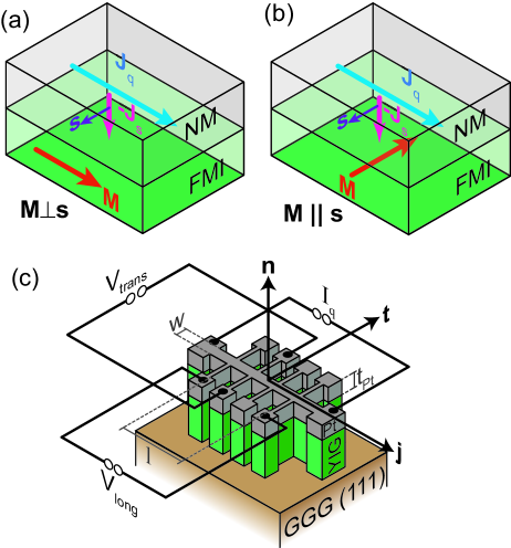
We consider first a charge current density flowing along (Fig. 2(c)) through the NM layer as indicated by the blue arrow in Fig. 2(a). This charge current induces a spin current due to the SHE in the NM layer, which flows across the NM/FMI interface, depicted as the magenta arrow in Fig. 2(a). The spin orientation of is oriented perpendicular to and because of the SHE (cf. Eq.(1)). At the FMI/NM interface, this spin current can exert a torque on and thus be absorbed by the ferromagnet if is not parallel to the magnetization of the ferromagnet. This absorption can only occur in a non-collinear configuration of and , since it only then is possible to transfer spin angular momentum from the spin current in the NM onto the magnetization of the FMI. In the Cartesian coordinate system defined by the unit vectors of the current direction (), the surface normal (), and the transverse direction (, see Fig. 2(c)) two different configurations are possible as illustrated by Fig. 2(a) and (b). In Fig. 2(a) the magnetization is oriented along and thus perpendicular to the spin polarization of such that the spin current is absorbed. Figure 2(b) illustrates the case when is oriented along and thus collinear to . In this case, the spin current cannot be absorbed by the FMI and is reflected at the interface. In the aforementioned Cartesian coordinate system, there is a third configuration where is oriented along . This case is analogous to Fig. 2(a), since and are again oriented perpendicular to each other, resulting in an absorption of the spin current. In this simple picture we expect a higher resistance of the NM layer if the spin current is absorbed at the FMI/NM interface, and a lower resistance if not, such that .
For a quantitative understanding of the SMR we need to calculate the spin diffusion process in a FMI/NM bilayer system and take into account the magnetization orientation dependence of the boundary conditions at the FMI/NM interface. Chen et al. (2013) These calculations are based on our first simplified theory presented in the supplements of our previous publication, Nakayama et al. (2012b) and show that the resulting steady state charge current density is composed of two contributions: one along the initial current direction and a second part along the transverse direction . This leads to a magnetoresistance effect in the NM, which is sensitive to the magnetization direction of the FMI. The effect can be parameterized as a longitudinal and transverse resistivity (cf. Fig. 2(c)) of the NM as a function of magnetization orientation of the FMI Limmer et al. (2006, 2008)
| (2) | ||||
| (3) |
According to the theoretical SMR model, . is the SMR effect. is a Hall-effect type resistivity. In addition to the conventional (ordinary) Hall effect of the Pt layer, also contains a Hall-type SMR contribution. Chen et al. (2013) While , , and are expected to be independent of the external magnetic field magnitude, the Pt OHE coefficient contribution to linearly changes Hall (1879) with , such that . The magnetization parameters , and are projections of the magnetization orientation unit vector onto the coordinate system given by the unit vectors , , and as illustrated in Fig. 2(c).
Following the calculations detailed in Ref. Chen et al., 2013, the relative magnitude of the SMR effect is given by the ratios
| (4) | ||||
| (5) |
Here, is the spin diffusion length in the NM, the resistivity of the NM, the thickness of the NM, and the real part and the imaginary part of the spin mixing interface conductance. The relative magnitude of this effect, i.e., the SMR magnitude , is essentially determined by . Taking the literature value for NM = Pt (Ref. Mosendz et al., 2010), one thus expects a relative resistance change for Pt. Moreover, the SMR effect will be large only if the thickness of the NM layer does not substantially exceed the spin diffusion length in the NM. Last but not least, the SMR magnitude also will characteristically depend on the resistivity and the spin mixing interface conductance , at least as long as .
It is important to compare Eqs.(2) and (3) to the anisotropic magnetoresistance (AMR) effect in conventional electrically conductive FMs Limmer et al. (2006):
| (6) | ||||
| (7) |
At first glance, AMR and SMR appear very similar. In particular, the SMR is not discernible from the AMR of a polycrystalline ferromagnetic conductor if the magnetization resides in the ferromagnetic film plane (i.e., the - plane). This directly follows from the unity relation , as we can rewrite into , for a magnetization oriented in the film plane (). In contrast, if has an out-of-plane component (), we expect a different behavior: the magnetization orientation dependence of the SMR vanishes for a rotation of the magnetization in the plane enclosed by and (oopt geometry, cf. Fig. 5(c)) since then . In contrast, the SMR depends on for a rotation of in the plane enclosed by and (oopj geometry in Fig. 5(b)) (). For the conventional AMR of a polycrystalline FM the situation is reversed: no dependence of the AMR in the - rotation plane (oopj geometry) and a clear dependence in the - rotation plane (oopt geometry). The SMR thus differs qualitatively from an AMR.
In our experiments we measure the magnetoresistance as a function of the magnetization orientation . More precisely, in these so-called angle-dependent magnetoresistance (ADMR) experiments, one records and as a function of the orientation of the externally applied magnetic field , while maintaining a fixed magnetic field magnitude . In the very same fashion as in ADMR experiments in (Ga,Mn)As thin films, Bihler et al. (2008); Limmer et al. (2008, 2006) we then use our SMR model equations to extract the , , , parameters from the experimental data. This requires the knowledge of for all field orientations and field strengths . To describe the magnetization orientation in the FMI we use the free enthalpy approach, with the expression
| (8) |
for the free enthalpy , which takes an effective shape anisotropy contribution () and the Zeeman energy with the external magnetic field direction into account. We intentionally neglect the (small) crystalline anisotropy of our YIG samples, since we only consider experimental data taken at magnetic fields much larger than the corresponding crystalline anisotropy fields. This allows to keep the number of free modeling parameters to a minimum. Using a numeric minimization algorithm, we determine the global minimum of the free enthalpy and assume that always points along this orientation. Please note that the free enthalpy in Eq.(8) is normalized to the saturation magnetization .
III Fabrication of FMI/NM hybrids
If not explicitly indicated otherwise, the samples used in the experiments are YIG/Pt or YIG/NM/Pt heterostructures grown on (111)-oriented gadolinium gallium garnet (GGG) or yttrium aluminium garnet (YAG) substrates (cf. Table 1). The YIG films were epitaxially grown via laser-MBE from a stoichiometric polycrystalline YIG target, utilizing a KrF excimer laser with a wavelength of at a repetition rate of . Gross et al. (2000); Opel (2012) A growth optimization yields the following optimum set of YIG growth parameters: substrate temperature during deposition, energy density at the target, and an oxygen atmosphere of . The NM layers were deposited in-situ, without breaking the vacuum, on top of the YIG film using electron beam evaporation, at room temperature.
After deposition, the structural and magnetic properties were investigated using high-resolution X-ray diffractometry (HRXRD) in a four circle diffractometer with monochromatic Cu K radiation, as well as superconducting quantum interference device (SQUID) magnetometry. The results obtained for YIG/Pt hybrids grown on GGG substrates are compiled in Fig. 3(a)-(d).
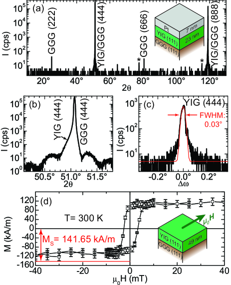
Figure 3(a) shows the sharp reflections of the GGG substrate and the laser-MBE grown YIG film in a --scan. The two low intensity reflections marked by asterisks () are due to substrate impurities. The YIG reflections, indicated by the arrow in Fig. 3(b) for the (444) plane, are only weakly discernible from the high intensity substrate reflection due to the small lattice mismatch of only between YIG and GGG. The high structural quality of the YIG layer is not influenced by the additional deposition of a Pt film as evident from Laue oscillations visible in the vicinity of the GGG (444) reflection in Fig. 3(b), which indicate a coherent, (111)-oriented growth of the YIG layer on GGG. From the position of the (444) reflection we calculate an interplane spacing of from the Bragg equation. Assuming an undistorted cubic lattice structure this leads to a lattice constant of , which is identical to the value of bulk YIG. Geller and Gilleo (1957) Our result is in contrast to published data on PLD grown YIG films. Manuilov et al. (2009); Krockenberger et al. (2008, 2009); Kahl and Grishin (2003) In these publications much larger lattice constants for the YIG layer have been reported, which result from a large rhombohedral distortion of the YIG lattice due to a deficiency of iron ions in the YIG structure. Manuilov et al. (2009); Dumont et al. (2005) The iron deficiency can be tuned by varying the oxygen partial pressure during deposition. Dumont et al. (2005) From this we conclude, that our growth parameters allow the deposition of highly stoichiometric YIG films from a stoichiometric polycrystalline target.
To evaluate the mosaic spread of the laser-MBE grown YIG films we recorded X-ray rocking curves of the YIG (444) reflection for our YIG film on GGG, one typical result is displayed in Fig. 3(c). From a Gaussian fit (red line) to the data we extract a FWHM of . This is an excellent value for laser-MBE grown thin films and confirms the high structural quality of our samples.
In the full range of the --scan (Fig. 3(a)) we do not observe any reflections which can be attributed to the Pt layer. We therefore assume that our Pt thin films are polycrystalline and grow without a preferential texture on YIG. We evaluated the surface roughness of the laser-MBE grown YIG/Pt hybrids on GGG substrates via X-ray reflectometry and obtain from a simulation on average for the surface roughness amplitude of the YIG film and for the Pt layer.
The YIG thin films deposited on diamagnetic, (111)-oriented YAG substrates (lattice mismatch: ) show similar structural properties. The --scans do not reveal any secondary phases. The FWHM of the YIG(444) rocking curves is about indicating a larger mosaic spread as compared to the films on lattice-matched GGG substrates. The X-ray reflectometry analysis gives on average a surface roughness amplitude of for the YIG film and for the Pt layer
Taken together, our laser-MBE grown YIG/Pt heterostructures exhibit excellent structural properties. Moreover, the structure of the YIG films is not influenced by the deposition of a Pt top layer.
The magnetic properties of our laser-MBE grown YIG films were analyzed using SQUID magnetometry. A hysteresis curve at is shown in Fig. 3(d), with the external magnetic field applied in the film plane. We subtracted the paramagnetic background signal of the GGG substrate and normalized the remaining magnetic moment to the volume of the 49 nm thick YIG layer to obtain the magnetization of the YIG film. The hysteresis curve exhibits a low coercive field and reaches a saturation magnetization , which is approximately 80% of the reported bulk value of YIG. Hansen, Röschmann, and Tolksdorf (1974) We note that due to the large paramagnetic background signal the error for the determination of the saturation magnetization is large (at least 10%) and thus alone might account for the measured difference to the bulk value (cf. error bars in Fig. 3(d)). Compared to the results reported by other groups, Krockenberger et al. (2008, 2009); Kahl and Grishin (2003); Manuilov et al. (2009); Dorsey et al. (1993); Sun et al. (2012) we can confirm that the saturation magnetization of YIG thin films on GGG substrates is close to the bulk value. However, the reported coercive fields in Refs. Kahl and Grishin, 2003; Manuilov et al., 2009; Dorsey et al., 1993 at are much lower (below ) than the one we observe in our YIG films (above ). On the other hand, the films described in Refs. Krockenberger et al., 2008, 2009 exhibit coercive fields as large as . From these variations in the literature values for coercive fields and keeping in mind that sensitively depends on the domain configuration, we conclude that the growth conditions greatly influence this quantity.
For the YIG layers on (111)-oriented, diamagnetic YAG substrates, we obtain a saturation magnetization of at , close to the bulk value of YIG. The extracted coercive field at for these samples is slightly larger than the values obtained for YIG films on GGG substrates. Nevertheless, these magnetic properties confirm the state-of-the-art quality of our laser-MBE grown YIG thin films.
An additional set of YIG/Pt heterostructures has been fabricated by sputtering a Pt layer on a commercially available (FDK Corporation), thick YIG layer deposited on (111)-oriented GGG substrates via liquid phase epitaxy. The YIG film was grown under a PbO-B2O3 flux at around . For our liquid phase epitaxy prepared YIG/Pt heterostructures we find in XRD studies a FWHM of the rocking curve for the YIG (444) reflection that is as narrow as the GGG (444) substrate reflection. Magnetization measurements on our liquid phase epitaxy YIG films yield at close to the reported bulk value of YIG. Hansen, Röschmann, and Tolksdorf (1974)
The Fe3O4/Pt hybrid structure used in our experiments was also fabricated by laser-MBE and electron beam evaporation. First the magnetite layer was grown via laser-MBE on a (001)-oriented MgO substrate using a polycrystalline Fe3O4 target, with the following set of deposition parameters: Reisinger et al. (2004); Venkateshvaran et al. (2009) substrate temperature during deposition, energy density at the target, and an argon atmosphere of . After the magnetite growth, the Pt layer was deposited in-situ on top of the Fe3O4 film using electron beam evaporation, at room temperature. Structural characterization via HRXRD showed that no secondary phases were present in the samples. Satellites due to Laue oscillations around the Fe3O4 (004) reflection and a narrow rocking curve of the (004) film reflection with a FWHM of indicate the excellent structural quality of these magnetite films. Reisinger et al. (2004); Venkateshvaran et al. (2009) SQUID magnetometry measurements Reisinger et al. (2004); Venkateshvaran et al. (2009) on these samples yield close to the bulk value of at (Ref. Landolt-B rnstein, 1970). A Verwey transition at is visible indicating the perfect stoichiometry of the Fe3O4 thin film.
The nickel ferrite (NiFe2O4) layer was grown via direct liquid injection chemical vapor deposition on (001)-oriented MgAl2O4 Li et al. (2011) at a substrate temperature of using Ni(acac)2 and Fe(acac)3 (acac=acetylacetonate) as precursors. The Pt layer was sputtered ex-situ, after cleaning the surface of the nickel ferrite by Ar ion beam milling, at room temperature. The rocking curve of the NiFe2O4 (004) reflection exhibited a FWHM of measured via HRXRD. The magnetic properties were evaluated via an alternating gradient magnetometer and yield a saturation magnetization Li et al. (2011) of (bulk value McGuire and Boyd (1970) ).
IV ADMR experiments on YIG/Pt hybrids
For the magnetotransport experiments we patterned Hall bar mesa structures out of the plain, laser-MBE grown YIG/Pt films using photolithography and argon ion beam milling. The width and length of the Hall bar were and , respectively (Fig. 2(c)). We measure the magnetotransport at temperatures between 5 K and 300 K in a liquid He magnet cryostat system in magnetic fields of up to . The magnetoresistance was studied by applying a constant dc bias current density in the range of to along the Hall bar while recording the longitudinal and transverse voltage signals (Fig. 2(c)) of the Hall bar as a function of the external magnetic field magnitude or orientation . For the further evaluation we calculated the longitudinal and transverse resistivity , where is the separation between the longitudinal voltage contacts and the width of the Hall bar. Within the range of charge current densities quoted above, the resistivities were independent of . We note that a reference sample consisting of a single, laser-MBE grown YIG () layer on a GGG substrate was found to be electrically insulating within our experimental limits. This gives a lower limit for the resistivity of our YIG layers , which is in agreement with the reported resistivity values for bulk YIG Sirdeshmukh et al. (1998) ().
In a first set of experiments we verified the existence of a magnetoresistance effect in our hybrids Weiler et al. (2012a); Nakayama et al. (2012a); Huang et al. (2012); [Shortlybeforesubmissionofthemanuscript; webecameawareofthispublicationonthearXiv:]vlietstra_spin-hall_2013 by recording the resistance evolution as a function of the applied external magnetic field strength ( measurements).
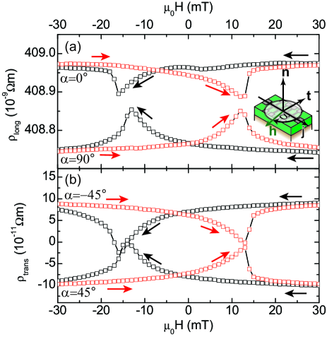
Figure 4(a) and (b) show the results obtained at from YIG()/Pt() bilayer grown on a (111)-oriented GGG substrate via laser-MBE. For the external -field oriented parallel to the current direction () we observe characteristic hysteretic changes of around magnetic field values, that are larger than the coercive field values (cf. Fig. 3(d)). We attribute these differences to the Hall bar structuring process of the YIG/Pt hybrids. Upon changing the in-plane field orientation such that is oriented perpendicular to (), the hysteretic behavior is inverted. Moreover, the resistivity values for are clearly different for and . This dependence of the magnetoresistance on the external field orientation is expected from our theoretical model of the SMR (cf. Eq.(2)) and reflects the evolution of the magnetization orientation as a function of the external magnetic field magnitude in close analogy to the AMR effect. A similar behavior is expected for the transverse resistivity . From Eq.(3) the characteristic inversion should be most prominent for magnetic field orientations and . Our measurements in Fig. 4(b) clearly confirm these expectations. Unfortunately, it is not straightforward to distinguish directly between the polycrystalline AMR (Eqs.(6), (7)) and the SMR (Eqs.(2), (3)) effect from single measurements. Moreover, a quantitative evaluation of the MR effect from these type of measurements is difficult, since magnetic domain formation around influences the observed MR signal, while domain configurations are not taken into account in Eqs.(2), (3) or Eqs.(6), (7).
ADMR measurements are not hampered by domain configuration issues. In an ADMR measurement an external magnetic field of constant magnitude is rotated in a given plane with respect to the sample, while and are recorded as a function of this external magnetic field orientation. We here performed ADMR experiments in 3 rotation planes: ip, oopj, oopt. Herby, ip stands for a rotation of around (angle ), oopj for a rotation of around (angle ), and oopt for a rotation of around (angle ). For the definitions of , , and see the illustrations in Fig. 5(a),(b), and (c), respectively, in which the field orientation is also shown. Prior to the angular variation we initialize the magnetization by applying along (ip), (oopj, oopt). In our measurements we choose to be at least one order of magnitude larger than the coercive field of YIG, such that the FMI is in a single domain state.
We begin the evaluation of the SMR with the analysis of the ADMR results obtained from a laser-MBE grown YIG ()/Pt () hybrid structure at . The experimental results are summarized in Fig. 5(a)-(c).
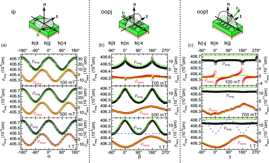
For the ADMR experiments with an ip magnetic field rotation at , , and , depicted in Fig. 5(a), we observe an angular dependence with a period of and a maximum in for parallel () or antiparallel () to and a minimum for parallel () or antiparallel () to for every magnitude . Due to the small in-plane magnetic anisotropy of the YIG layer its magnetization is oriented parallel to the external magnetic field in good approximation for all . This allows to directly use to determine the magnetization orientation. Thus is expected to follow a dependence in accordance to Eq.(2), which is nicely reproduced by our ADMR data for all magnetic fields (lines in Fig. 5(a)). In addition, the transverse resistance exhibits a dependence. We observe a maximum in at and , while the minimum is located at and . For both and the amplitude of the angular dependence is not influenced by the external magnetic field strength, and as expected.
In case of the oopj rotation plane (Fig. 5(b)) we observe maxima in at and located at () and (). The minima in occur at () and (). At the longitudinal resistivity again exhibits a dependence. Upon reducing the shape anisotropy increasingly influences the orientation of the magnetization in YIG, which results in deviations from the dependence. Limmer et al. (2006) For the transverse resistivity we now observe a completely different angular dependence with a period of . has a minimum at () and a maximum at (). The amplitude of this dependence of strongly dependens on the external magnetic field strength (cf. Fig. 7). This is the signature of the ordinary Hall effect of the Pt layer. The abrupt changes at , visible in and , originate from the in-plane reorientation of the magnetization forced by the demagnetization energy, if the field is rotated near or .
Interestingly, the angular dependence of vanishes for the oopt rotation plane (Fig. 5(c)). This is in contrast to the expected angular dependence of an AMR of a polycrystalline FM (cf. Eq.(6)), but is fully consistent with our SMR model (cf. Eq.(2)). Thus, we can exclude an AMR effect as the source of the observed MR. For we again find a angular dependence, which dominantly stems from the ordinary Hall effect in Pt. The abrupt changes in and visible at are explained by the abrupt in-plane reorientation of the magnetization, when the field orientation is rotated near or .
Huang et al. also observed a MR in YIG/Pt bilayers Huang et al. (2012) and attributed it to an AMR effect originating from an induced magnetism (static magnetic proximity effect) in the Pt layer. As discussed in the context of Fig. 5, our results suggest that systematic measurements as a function of orientation in out-of-plane geometries allow to distinguish between SMR and AMR. The angular dependence we observe in our samples (Fig. 5(c)) can be consistently explained by the SMR model presented in Sect. II, while conventional AMR can be ruled out as an explanation for the observed magnetoresistance.
For a quantitative analysis, we now employ the simulation technique successfully used for ADMR in (Ga,Mn)As Bihler et al. (2008); Limmer et al. (2008, 2006) and Heusler compounds Muduli et al. (2005). First we choose a starting value for the anisotropy constant and determine the magnetization direction for every magnetic field orientation by numerically minimizing the free enthalpy given by Eq.(8). We then calculate and using and a set of parameters via Eqs.(2), (3). An iterative optimization process of and the parameters is carried out, until we achieve a satisfactory agreement () between experiment and simulation for all rotation planes and magnitudes with a single set of and . For the simulation, all parameters except were taken to be independent of the external magnetic field strength. The simulation curves obtained in this way are depicted as green lines in Fig. 5(a)-(c) and reproduce the experimental data very well. The respective parameters are summarized in Table 1 and we obtained from the simulation.
| sample | [K] | [m] | [m] | ||
|---|---|---|---|---|---|
| GGG/YIG(54)/Pt(7) | 300 | 406.5 | |||
| GGG/YIG(54)/Pt(7) | 30 | 283.5 | |||
| GGG/YIG(54)/Pt(7) | 5 | 208.7 | |||
| GGG/YIG(61)/Pt(1.1) | 300 | 1895.9 | |||
| GGG/YIG(55)/Pt(1.2) | 300 | 1857.3 | |||
| GGG/YIG(57)/Pt(1.3) | 300 | 1089.9 | |||
| GGG/YIG(29)/Pt(1.8) | 300 | 487.4 | |||
| GGG/YIG(58)/Pt(2.2) | 300 | 761.7 | |||
| GGG/YIG(69)/Pt(2.7) | 300 | 453.6 | |||
| GGG/YIG(53)/Pt(2.5) | 300 | 719.0 | |||
| GGG/YIG(46)/Pt(3.5) | 300 | 306.6 | |||
| GGG/YIG(65)/Pt(6.6) | 300 | 582.6 | |||
| GGG/YIG(50)/Pt(7) | 300 | 409.4 | |||
| GGG/YIG(53)/Pt(8.5) | 300 | 348.3 | |||
| GGG/YIG(61)/Pt(11.1) | 300 | 334.5 | |||
| GGG/YIG(52)/Pt(16.9) | 300 | 339.2 | |||
| GGG/YIG(55)/Pt(17.2) | 300 | 331.7 | |||
| YAG/YIG(45)/Pt(1.9) | 300 | 1331.3 | |||
| YAG/YIG(60)/Pt(2.5) | 300 | 358.4 | |||
| YAG/YIG(64)/Pt(3) | 300 | 622.2 | |||
| YAG/YIG(50)/Pt(3) | 300 | 539.3 | |||
| YAG/YIG(63)/Pt(6.5) | 300 | 412.0 | |||
| YAG/YIG(59)/Pt(6.8) | 300 | 487.7 | |||
| YAG/YIG(60)/Pt(9.7) | 300 | 429.0 | |||
| YAG/YIG(60)/Pt(12.8) | 300 | 434.9 | |||
| YAG/YIG(61)/Pt(19.5) | 300 | 361.3 | |||
| YAG/YIG(46)/Pt(21.7) | 300 | 358.7 | |||
| GGG/YIG(15)/Au(8)/Pt(7) | 300 | 143.0 | |||
| GGG/YIG(34)/Cu(9)/Pt(6) | 300 | 111.0 | |||
| MgO/Fe3O4(20)/Pt(7) | 5 | 202.6 | |||
| MgAl2O4/NiFe2O4(620)/Pt(10) | 300 | 242.0 |
The parameters extracted from our simulation show . This corroborates the prediction based on the qualitative description of the SMR effect.
The MR of the laser-MBE grown YIG/Pt heterostructure only changes slightly with temperature. At , is reduced by 34% as compared to . This decrease can be caused by a temperature dependence of the spin mixing conductance Czeschka et al. (2011), the spin diffusion length, and the spin Hall angle. However, more experiments are required to further clarify this issue. Moreover, is independent of the current density in the sample, such that thermal gradients generated via Joule heating can be excluded as a source of the MR effect.
From the quantitative description of the SMR effect (Eq.(4)) it is evident that the SMR sensitively depends on the Pt layer thickness. We have thus used a set of samples with different Pt thicknesses and evaluated the SMR effect from ADMR experiments to extract the parameters in an iteration process as described above. The results of this procedure are compiled in Table 1. The ratio is plotted as a function of the Pt thickness in Fig. 6(a).
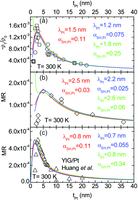
We clearly observe a maximum of the SMR in our samples (black symbols) at a Pt thickness of around with a ratio of . A simulation of the experimental data using Eq.(4) allows us to extract the relevant material parameters from this film thickness dependence of the SMR. We however would like to emphasize that the parameter values thus obtained sensitively depend on and the value used for . In the analysis, we explicitly took the film thickness dependence of into account by fitting Eq.(9) to the Pt thickness dependence of (see Fig. 9(a)) in the simulation. Note also that for values of that are smaller than the surface roughness , Eq.(9) is no longer applicable, which puts a lower limit on the range of Pt thicknesses considered in the simulation. We note that is the charge transport mean free path for an infinitely thick film (see Appendix A); for a finite thickness the charge transport mean free path decreases with decreasing thickness. Fischer, Hoffmann, and Vancea (1980). When surface roughness limits transport () our SMR model based on the spin diffusion equation is no longer applicable. We can model such a regime by introducing a spin diffusion length or spin-flip relaxation time that depends on thickness of the metal layer. Valenzuela and Tinkham (2006); Erekhinsky et al. (2010); Poli et al. (2006); Vila, Kimura, and Otani (2007) A transport theory based on Boltzmann equations is better suited to treat the thickness dependence of the SMR in the presence of significant surface roughness scattering. However, such a more elaborate theoretical description is way beyond the scope of the present paper. In particular, the solutions of a Boltzmann-type spin transport approach most likely will not be analytical anymore. In contrast, the simple spin diffusion model we use here does yield analytical expressions, which allows to pinpoint the microscopic nature of the physical mechanisms. Realizing the limitations of our model, we focus on samples with for the parameter optimization, since in this limit, the spin diffusion approach should yield a reasonable description of the spin transport processes. To capture the impact of we use three different typical values to show the influence of this parameter on the extracted and . For (cf. Jia et al. Jia et al. (2011)) we obtain a satisfactory agreement between simulation and experiment (red line in Fig. 6(a)) for , . For a lower value , , yield the best agreement between experiment and simulation (green line in Fig. 6(a)). By choosing a higher value , we achieve for , the lowest deviation between experiment and simulation (blue line in Fig. 6(a)). However, the simulated SMR thickness dependence for diverges for small , while the simulation for and nicely reproduces also the thickness dependence of the experimental data for small . Since the value appears unreasonably high, when compared to the theoretical calculations by Jia et al.. Jia et al. (2011), we conclude that is most appropriate for our samples. The modeling for what we perceive to be reasonable values nicely reproduce the experimentally observed thickness dependence also in the limit of very thin Pt films (). While the validity of the diffusive model is questionable in this limit, the Boltzmann corrections appear to be small. Nevertheless, a more elaborate theoretical evaluation is needed to clarify this point.
In an independent set of experiments we investigated the Pt thickness dependence of the SMR in YIG/Pt heterostructures fabricated via liquid phase epitaxy (YIG) and sputtering (Pt) on (111)-oriented GGG substrates Nakayama et al. (2012a). These samples were structured into Hall bars with and . In this measurement series the longitudinal MR was determined from curves for each sample. The results of this analysis are shown in Fig. 6(b). For these samples we observe a maximum of the MR for a Pt thickness of around with a MR ratio of . Following the same procedure as above, we included the thickness dependence of via a fit of Eq.(9) to the Pt thickness dependence of (see Fig. 9(b)). For (red line in Fig. 6(b)) we obtain , , with satisfactory agreement between simulation and experiment. For a smaller (green line in Fig. 6(b)) the parameters change to , . A higher (blue line in Fig. 6(b)) yields , . Again, the simulation for reproduces the experimental thickness dependence very well and is consistent with the theoretical calculations of for YIG/noble metal interfaces.
In the publication of Huang et al. Huang et al. (2012) the thickness dependence of the longitudinal MR in YIG/Pt heterostructures has also been investigated, the data taken from their publication are depicted in Fig. 6(c). Their MR thickness dependence has a maximum located also at a Pt thickness of with a value of . A simulation of their data set with Eq.(4) using (we use an average Pt sheet resistivity as no data on the thickness dependence is given in this publication) yields and for , with an excellent agreement between data and simulation (red line in Fig. 6(c)). For the parameters in the simulation change to and (green line in Fig. 6(c)). (blue line in Fig. 6(c)) gives and . As we now used a thickness independent for the simulation in Fig. 6(c), the simulation does not diverge for small . While we anticipate that an inclusion of a thickness dependent will affect the values for and to some extent, the good agreement between the experimental data of Huang et al. Huang et al. (2012) and our SMR simulation suggest that the SMR effect also plays a crucial role in their experiment.
The spin diffusion lengths extracted from the three independent data sets in Fig. 6 compare reasonably well. The extracted depends on the assumed and changes for our 3 evaluated values by . While for a fixed the relative error for is less than . Moreover, the spin diffusion length is comparable with the value of the charge transport mean free path in Pt (see Appendix A). For we find , while is obtained for . A Boltzmann theory for the SMR at least at the level of the Fuchs-Sondheimer model will yield more insight into this problem. Also is strongly correlated with and it is currently unclear whether size effects enhance or reduce the SMR effect magnitude, leading to an effective, thickness dependent . The parameter values extracted from our analysis thus should be considered with this caveat in mind. We attribute the differences in and obtained for the different sets of samples to the different deposition techniques for the Pt layer. Nevertheless, the values obtained from Fig. 6 deviate from those by Mosendz et al. Mosendz et al. (2010) for Pt. Calculations Gradhand et al. (2010) suggest that impurities can substantially change the magnitude of the spin Hall angle, while they only slightly alter the spin diffusion length in Pt. In one of our recent publications we investigated the spin pumping effect in various conductive ferromagnet/Pt heterostructures Czeschka et al. (2011) and obtained a scaling relation, using the material constants quoted by Mosendz et al. Mosendz et al. (2010) for Pt. We would like to note that the scaling relation also holds for the Pt parameter values we extracted from the SMR experiments in Fig. 6. Using and we obtain a spin mixing conductance in conductive ferromagnet/Pt bilayers of , corroborating the analysis of the SMR experiments above.
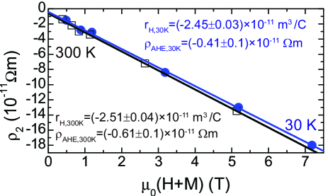
We now address the Hall effect in our laser-MBE grown YIG/Pt hybrids in more detail. The field dependence of for and extracted from the simulation of our ADMR data is shown in Fig. 7 for the very same sample as shown in Fig. 5 (YIG ()/Pt ()). We here plot versus the magnetic inductance to take into account the additional magnetic field in the Pt layer due to the magnetization of the YIG. The analysis is only conducted for as only then the magnetization of the YIG layer is saturated and oriented along the external magnetic field direction. For we use determined from SQUID magnetometry (Fig. 3(d)). For we extrapolated the saturation magnetization from using the temperature dependence of bulk YIG Hansen, Röschmann, and Tolksdorf (1974) and obtain . A direct determination of the saturation magnetization via SQUID magnetometry at this temperature is not possible because of the paramagnetism of the GGG substrate. At both temperatures increases linearly with increasing magnetic field (), as one would expect for an OHE. Hall (1879) A linear fit to the data to extract the Hall coefficient of our Pt yields for both temperatures. This value is close to reported in Ref. Greig and Livesey, 1972 for evaporated Pt films. Moreover, we find a non vanishing abscissa at and at . This effect can be understood within our theoretical model Chen et al. (2013) of the SMR effect, which predicts an anomalous Hall-like SMR contribution due to the imaginary part of the spin mixing conductance (cf. Eq(5)). From our experiment we obtain for a ratio at . Using the parameters , , and Eq.(5) we extract from the experiment. This gives which nicely agrees with theoretical calculations Jia et al. (2011) (). The quantitative agreement between theory and experiment for both magnetoresistance and Hall-type measurements confirms the existence of the SMR effect. Note that an induced ferromagnetism at the YIG/Pt interface Geprägs et al. (2012); Huang et al. (2012); Jaouen et al. (2005); Wilhelm et al. (2000); Poulopoulos et al. (2003) might also contribute an AHE signal. However, our quantitative analysis of the Hall data, together with the MR data with out-of-plane magnetization have little room for such a static, magnetic proximity induced MR effect.
While the magnetoresistive behavior observed in our YIG/Pt samples is not consistent with an induced magnetization (static magnetic proximity effect) in the Pt close to the YIG/Pt interface, an experiment to rule out magnetic proximity as the origin of the SMR is desirable. In a recent publication, Geprägs et al. (2012) we employed XMCD measurements to detect element-specific magnetic moments at the Pt -edge in the very same laser-MBE grown samples also used for SMR measurements presented here. The XMCD measurements showed that the induced magnetic proximity moment in Pt – if present at all – is small in our samples. However, the available XMCD data do not allow to exclude a static proximity effect in Pt, only an upper limit can be put on the induced Pt moment. Therefore, another set of experiments addressing the magnetic proximity effect in Pt is desirable.
Following the same line of argument as in our previous publication on the SMR, Nakayama et al. (2012a) we also investigated the impact of a NM layer between YIG and Pt on the SMR. In Fig. 8(a)-(d) we show the ADMR signals of a laser-MBE grown YIG ()/Au ()/Pt () and a laser-MBE grown YIG ()/Cu ()/Pt () heterostructure. We note that the discrepancy between the green simulation curve and the experimental data in the ip rotation for both samples arises from a small out-of-plane external field component caused by a slightly tilted rotation plane (). This experimental misalignment leads to a superimposed dependence. As the OHE and AHE contribution is comparable to in these samples, a slight tilting in the experiment from the ideal ip rotation plane already leads to a considerable deviation between experiment and simulation.
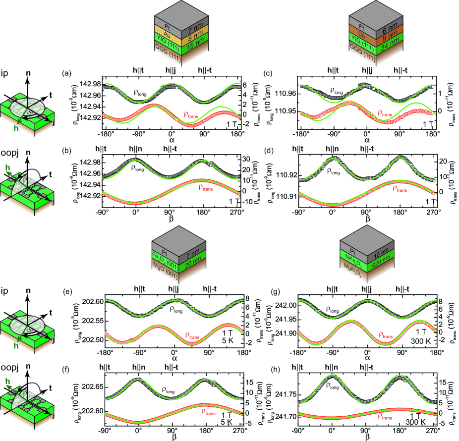
The ADMR signal (Fig. 8(a)-(d)) from the laser-MBE grown YIG/NM/Pt samples is qualitatively identical to the ADMR from YIG/Pt (Fig. 5). ADMR experiments in YIG (45 nm)/Au (7 nm) and YIG (45 nm)/Cu (7 nm) samples without Pt top layers did not reveal any variation of the resistance with oriented in-plane within our experimental resolution. From these experiments, we obtain an upper limit of for YIG/NM samples without Pt (data not shown here). As mentioned in Sec. II the maximum is strictly smaller than . Assuming for Au (Ref. Mosendz et al., 2010), one estimates , which presently is below our experimental resolution. Thus, we are currently unable to resolve the SMR in FMI/Au hybrids. These results demonstrate that the MR effect observed in FMI/Pt and FMI/NM/Pt samples indeed is related to spin currents. In particular, a static magnetic proximity effect, i.e., an induced magnetic moment in the Pt layer, can be ruled out based on these experiments, since a magnetic proximity effect can not persist over 8 to 9 nm of Cu or Au. Bailey et al. (2012) For the SMR, only the conversion of a charge current into a spin current and back into a charge current via the SHE/ISHE in the Pt and the transport of spin current from the Pt to the YIG are necessary. Thus, the SMR persists even when a NM layer is inserted, provided that the spin current can propagate through this NM layer. The extracted quantitative data for all heterostructures from the ADMR simulation are summarized in Table 1. decreases with increasing total NM/Pt layer thickness, since in these double NM structures the two parallel conducting layers both contribute to the total resistivity and since the Au and Cu layer have higher conductivity. The two-layer parallel conductance is also evidenced by the increase in compared to the YIG/Pt hybrid structure, due to the larger absolute Hall constant of Cu and Au. Henriquez et al. (2010); Schindler and Pugh (1953) The ratio decreases by a factor of 3 for the YIG/Au/Pt heterostructure compared to the YIG/Pt reference sample. For the YIG/Cu/Pt heterostructure the ratio even decreases by a factor of 7. This decrease in the SMR effect can be rationalized in terms of the exponential decay of the spin current determined by the spin diffusion length in the NM and the parallel conduction channel which NM represents. A quantitative theoretical description would be highly desirable, since it would possibly allow to use SMR experiments in YIG/NM/Pt hybrids with varying NM thickness to extract the spin diffusion length in more complex structures using simple ADMR experiments in the future.
Finally, we show that the SMR effect is not limited to FMI/NM heterostructures based on the ferromagnetic insulator YIG. According to our model any FMI/NM bilayer in which the resistance of the FMI is several orders of magnitude larger than the resistance of the NM layer (such that the resistance of the NM dominates) should exhibit a SMR. To verify this conjecture we also investigated samples based on other ferromagnetic insulators and semiconductors. One sample consists of a thick, (001)-oriented magnetite (Fe3O4) layer on a (001)-oriented MgO substrate covered in-situ by an electron beam evaporated, thin, Pt film. We note that the resistivity Reisinger et al. (2004) of Fe3O4 is of the order of at , which is two orders of magnitude larger than the sheet resistivity of the Pt layer. Therefore, we performed the ADMR measurements at below the Verwey transition, where Fe3O4 becomes semi-insulating, Venkateshvaran et al. (2009) such that the conductance is dominated by the Pt layer (Fig. 8(e,f)). We note that the observed SMR ratio and the respective parameters for our Fe3O4/Pt heterostructure depend on the externally applied magnetic field, which is caused by the high saturation field of Fe3O4 due to antiphase boundaries in the film. Reisinger et al. (2004) 111At we still observe the ADMR signature of the SMR superimposed on a weak AMR signal of the Fe3O4 layer, as the resistance of the Pt layer is still 2 orders of magnitude smaller than the resistance of the magnetite layer. Another independent sample consists of a semiconducting, thick nickel ferrite (NiFe2O4) layer on a (001)-oriented MgAl2O4 substrate with an ex-situ, sputter deposited thick Pt layer (Fig. 8(g,h)). The resistivity of these NiFe2O4 films is at with a bandgap of . We then performed ADMR experiments in ip, oopj, and oopt geometry as described above. In Fig. 8(e)-(h) we show the corresponding results for the ip and oopj geometry. The parameters of the fits extracted from the experiments at are summarized in Table 1. In all cases the fits reproduce very well the angular evolution of the data. The MR observed in experiment thus is consistent with SMR, but inconsistent with AMR. Taken together, we thus have observed the SMR effect in all FMI/Pt and FMI/NM/Pt samples studied.
V Conclusions
In summary, we have quantitatively investigated the SMR effect in FMI/Pt and FMI/NM/Pt heterostructures. The SMR effect is based on the conversion of a charge to a spin current via the spin Hall effect, and back to a charge current via the inverse spin Hall effect in the NM (Pt) layer. The SMR effect characteristically depends on the absorption of the spin current at the FMI/Pt or FMI/NM interface, which in turn can be tuned via the orientation of the magnetization of the FMI with respect to the spin polarization of the spin current. Thus, the SMR effect enables a remote sensing of the magnetization direction in the FMI by simply measuring the resistance of the adjacent NM layer. We have shown that the signature of SMR is qualitatively different from conventional AMR, in particular when the magnetization has a component perpendicular to the Pt film plane. Magnetotransport measurements as a function of the magnetization orientation, rotating the magnetization from within the sample plane to a perpendicular-to-plane orientation, thus allow to disentangle AMR and SMR. We have observed SMR in YIG/Pt hybrids, as well as in YIG/Au/Pt, YIG/Cu/Pt, Fe3O4/Pt and NiFe2O4/Pt heterostructures. These results confirm the SMR thus as a universal and robust effect, that is not limited to certain material combinations. This allows to use the SMR in a wide variety of material combinations. Moreover, the excellent quantitative agreement between theory and experiment clearly show that a static magnetic proximity effect is not the origin of the observed MR in FMI/NM hybrids. We demonstrated that our quantitative model for the SMR effect allows us to extract the spin Hall angle and the spin diffusion length of Pt from SMR experiments, by examining the thickness dependence of the SMR effect. This enables to use the SMR for the determination of the spin diffusion length and spin Hall angle in various NMs. The SMR is a novel, simple to measure magnetoresistance effect, which paves the way for new spin current related experiments. Last but not least, our SMR theory predicts a small AHE-like SMR contribution to the transverse resistivity due to the imaginary part of the spin mixing conductance. In our experiments we find at for .
Acknowledgements.
Financial support via SPP 1538 ”Spin-Caloric Transport” (project no. GO 944/4-1 and RE 1052/24-1), FOM (Stichting voor Fundamenteel Onderzoek der Materie), EU-ICT-7 ”MACALO”, the ICC-IMR, a Grant-in-Aid for JSPS Fellows, and the Nanosystems Initiative Munich (NIM) is gratefully acknowledged. The work at the University of Alabama was supported by NSF-ECCS Grant No. 1102263. M.A., S.M., M.S., S.A., M.W., H.H., S.G., M.O., R.G., and S.T.B.G. thank A. Erb for the preparation of the polycrystalline laser-MBE targets and T. Brenninger for technical support.Appendix A Thickness dependence of Pt resistivity
For the simulation of the thickness dependence of the SMR ratio it is necessary to also include the thickness dependence of . The thickness dependence of the resistivity for thin films has already been extensively studied in experiment and theory. Sondheimer (1952); Fuchs (1938); Hoffmann, Vancea, and Jacob (1985); Reiss et al. (1989); Namba (1970) For our analysis we use the expanded version of the Fuchs-Sondheimer theory, Sondheimer (1952); Fuchs (1938) that includes a surface roughness amplitude described by the parameter . In the limit that , the thickness dependence of can be written as: Fischer, Hoffmann, and Vancea (1980)
| (9) |
where is the resistivity, and the mean free path for an infinitely thick film. The parameter describes the scattering at the interfaces, for our analysis we strictly use the diffusive limit ().
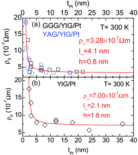
In Fig.9(a) we plotted the for different laser-MBE grown YIG/Pt () samples (cf. Table 1). As expected the resistivity increases with decreasing film thickness. By fitting the experimental data by Eq.(9) we obtain the following set of parameter: , , . Some experimental values deviate from the fitted theoretical curve as the assumption of a thickness independent surface roughness might be to simplistic. Nevertheless, the fitted curve reproduces the trend from our experiment and thus should be sufficient enough for the simulation of the SMR ratio. Moreover, the value for agrees nicely with the average surface roughness amplitude extracted from X-ray reflectometry measurements (cf. Section III). The results we find for the LPE grown YIG/Pt hybrids are depicted in Fig.9(b). Here a fit to the experimental data gives: , , . These two sets of parameter enable us to insert Eq.(9) into Eq.(4) to describe the thickness dependence of in our simulation in Fig. 6(a) and (b). Taking into account the different deposition techniques, these values compare reasonably well to published values by Fischer et al. Fischer, Hoffmann, and Vancea (1980) (, ) for Pt thin films evaporated onto glass substrates.
References
- Uchida et al. (2011a) K. Uchida, T. Ota, Y. Kajiwara, H. Umezawa, H. Kawai, and E. Saitoh, “Electric detection of the spin-Seebeck effect in magnetic insulator in the presence of interface barrier,” Journal of Physics: Conference Series 303, 012096 (2011a).
- Adachi et al. (2011) H. Adachi, J. Ohe, S. Takahashi, and S. Maekawa, “Linear-response theory of spin Seebeck effect in ferromagnetic insulators,” Physical Review B 83, 094410 (2011).
- Adachi et al. (2010) H. Adachi, K. Uchida, E. Saitoh, J. Ohe, S. Takahashi, and S. Maekawa, “Gigantic enhancement of spin Seebeck effect by phonon drag,” Applied Physics Letters 97, 252506 (2010).
- Uchida et al. (2009) K. Uchida, S. Takahashi, J. Ieda, K. Harii, K. Ikeda, W. Koshibae, S. Maekawa, and E. Saitoh, “Phenomenological analysis for spin-Seebeck effect in metallic magnets,” Journal of Applied Physics 105, 07C908 (2009).
- Xiao et al. (2010) J. Xiao, G. E. W. Bauer, K. Uchida, E. Saitoh, and S. Maekawa, “Theory of magnon-driven spin Seebeck effect,” Physical Review B 81, 214418 (2010).
- Uchida et al. (2010a) K. Uchida, T. Nonaka, T. Ota, and E. Saitoh, “Longitudinal spin-Seebeck effect in sintered polycrystalline (Mn,Zn)Fe2O4,” Applied Physics Letters 97, 262504 (2010a).
- Uchida et al. (2010b) K. Uchida, H. Adachi, T. Ota, H. Nakayama, S. Maekawa, and E. Saitoh, “Observation of longitudinal spin-Seebeck effect in magnetic insulators,” Applied Physics Letters 97, 172505 (2010b).
- Uchida et al. (2008) K. Uchida, S. Takahashi, K. Harii, J. Ieda, W. Koshibae, K. Ando, S. Maekawa, and E. Saitoh, “Observation of the spin Seebeck effect,” Nature 455, 778 (2008).
- Jaworski et al. (2010) C. M. Jaworski, J. Yang, S. Mack, D. D. Awschalom, J. P. Heremans, and R. C. Myers, “Observation of the spin-Seebeck effect in a ferromagnetic semiconductor,” Nature Materials 9, 898 (2010).
- Uchida et al. (2010c) K. Uchida, J. Xiao, H. Adachi, J. Ohe, S. Takahashi, J. Ieda, T. Ota, Y. Kajiwara, H. Umezawa, H. Kawai, G. E. W. Bauer, S. Maekawa, and E. Saitoh, “Spin Seebeck insulator,” Nature Materials 9, 894 (2010c).
- Jaworski et al. (2011) C. M. Jaworski, J. Yang, S. Mack, D. D. Awschalom, R. C. Myers, and J. P. Heremans, “Spin-Seebeck effect: A phonon driven spin distribution,” Physical Review Letters 106, 186601 (2011).
- Le Breton et al. (2011) J. Le Breton, S. Sharma, H. Saito, S. Yuasa, and R. Jansen, “Thermal spin current from a ferromagnet to silicon by Seebeck spin tunnelling,” Nature 475, 82 (2011).
- Slachter et al. (2010) A. Slachter, F. L. Bakker, J. Adam, and B. J. van Wees, “Thermally driven spin injection from a ferromagnet into a non-magnetic metal,” Nature Physics 6, 879 (2010).
- Weiler et al. (2012a) M. Weiler, M. Althammer, F. D. Czeschka, H. Huebl, M. S. Wagner, M. Opel, I. Imort, G. Reiss, A. Thomas, R. Gross, and S. T. B. Goennenwein, “Local charge and spin currents in magnetothermal landscapes,” Physical Review Letters 108, 106602 (2012a).
- Qiu et al. (2012) Z. Qiu, Y. Kajiwara, K. Ando, Y. Fujikawa, K. Uchida, T. Tashiro, K. Harii, T. Yoshino, and E. Saitoh, “All-oxide system for spin pumping,” Applied Physics Letters 100, 022402 (2012).
- Saitoh et al. (2006) E. Saitoh, M. Ueda, H. Miyajima, and G. Tatara, “Conversion of spin current into charge current at room temperature: Inverse spin-Hall effect,” Applied Physics Letters 88, 182509 (2006).
- Ando et al. (2010a) K. Ando, M. Morikawa, T. Trypiniotis, Y. Fujikawa, C. H. W. Barnes, and E. Saitoh, “Direct conversion of light-polarization information into electric voltage using photoinduced inverse spin-Hall effect in Pt/GaAs hybrid structure: Spin photodetector,” Journal of Applied Physics 107, 113902 (2010a).
- Ando et al. (2011a) K. Ando, S. Takahashi, J. Ieda, H. Kurebayashi, T. Trypiniotis, C. H. W. Barnes, S. Maekawa, and E. Saitoh, “Electrically tunable spin injector free from the impedance mismatch problem,” Nature Materials 10, 655 (2011a).
- Ando et al. (2010b) K. Ando, M. Morikawa, T. Trypiniotis, Y. Fujikawa, C. H. W. Barnes, and E. Saitoh, “Photoinduced inverse spin-Hall effect: Conversion of light-polarization information into electric voltage,” Applied Physics Letters 96, 082502 (2010b).
- Ando et al. (2011b) K. Ando, S. Takahashi, J. Ieda, Y. Kajiwara, H. Nakayama, T. Yoshino, K. Harii, Y. Fujikawa, M. Matsuo, S. Maekawa, and E. Saitoh, “Inverse spin-Hall effect induced by spin pumping in metallic system,” Journal of Applied Physics 109, 103913 (2011b).
- Hoffmann (2007) A. Hoffmann, “Pure spin-currents,” physica status solidi (c) 4, 4236 (2007).
- Ando and Saitoh (2012) K. Ando and E. Saitoh, “Observation of the inverse spin Hall effect in silicon,” Nature Communications 3, 629 (2012).
- Czeschka et al. (2011) F. D. Czeschka, L. Dreher, M. S. Brandt, M. Weiler, M. Althammer, I. Imort, G. Reiss, A. Thomas, W. Schoch, W. Limmer, H. Huebl, R. Gross, and S. T. B. Goennenwein, “Scaling behavior of the spin pumping effect in Ferromagnet-Platinum bilayers,” Physical Review Letters 107, 046601 (2011).
- Uchida et al. (2011b) K. Uchida, T. An, Y. Kajiwara, M. Toda, and E. Saitoh, “Surface-acoustic-wave-driven spin pumping in Y3Fe5O12/Pt hybrid structure,” Applied Physics Letters 99, 212501 (2011b).
- Weiler et al. (2012b) M. Weiler, H. Huebl, F. S. Goerg, F. D. Czeschka, R. Gross, and S. T. B. Goennenwein, “Spin pumping with coherent elastic waves,” Physical Review Letters 108, 176601 (2012b).
- Brataas et al. (2002) A. Brataas, Y. Tserkovnyak, G. E. W. Bauer, and B. I. Halperin, “Spin battery operated by ferromagnetic resonance,” Physical Review B 66, 060404 (2002).
- Kajiwara et al. (2010) Y. Kajiwara, K. Harii, S. Takahashi, J. Ohe, K. Uchida, M. Mizuguchi, H. Umezawa, H. Kawai, K. Ando, K. Takanashi, S. Maekawa, and E. Saitoh, “Transmission of electrical signals by spin-wave interconversion in a magnetic insulator,” Nature 464, 262 (2010).
- Heinrich et al. (2011) B. Heinrich, C. Burrowes, E. Montoya, B. Kardasz, E. Girt, Y.-Y. Song, Y. Sun, and M. Wu, “Spin pumping at the magnetic insulator (YIG)/Normal metal (Au) interfaces,” Physical Review Letters 107, 066604 (2011).
- Nakayama et al. (2012a) H. Nakayama, M. Althammer, Y.-T. Chen, K. Uchida, Y. Kajiwara, D. Kikuchi, T. Ohtani, S. Geprägs, M. Opel, S. Takahashi, R. Gross, G. E. W. Bauer, S. T. B. Goennenwein, and E. Saitoh, “Spin Hall magnetoresistance induced by a non-equilibrium proximity effect,” (2012a), (accepted by PRL 2013), arXiv:1211.0098 [cond-mat.mtrl-sci] .
- Chen et al. (2013) Y.-T. Chen, S. Takahashi, H. Nakayama, M. Althammer, S. T. B. Goennenwein, E. Saitoh, and G. E. W. Bauer, “Theory of spin Hall magnetoresistance,” Physical Review B 87, 144411 (2013).
- Vlietstra et al. (2013) N. Vlietstra, J. Shan, V. Castel, J. B. Youssef, and B. J. van Wees, “Spin-Hall magnetoresistance in platinum on yttrium iron garnet,” (2013), arXiv:1301.3266 [cond-mat.mes-hall] .
- Dyakonov and Perel (1971) M. Dyakonov and V. Perel, “Current-induced spin orientation of electrons in semiconductors,” Physics Letters A 35, 459 (1971).
- Hirsch (1999) J. E. Hirsch, “Spin Hall effect,” Physical Review Letters 83, 1834 (1999).
- Takahashi and Maekawa (2008) S. Takahashi and S. Maekawa, “Spin current, spin accumulation and spin Hall effect,” Science and Technology of Advanced Materials 9, 014105 (2008).
- McGuire and Potter (1975) T. McGuire and R. Potter, “Anisotropic magnetoresistance in ferromagnetic 3d alloys,” IEEE Trans. Magn. 11, 1018 (1975).
- Meier et al. (2013) D. Meier, T. Kuschel, L. Shen, A. Gupta, T. Kikkawa, K. Uchida, E. Saitoh, J.-M. Schmalhorst, and G. Reiss, “Thermally driven spin and charge currents in thin NiFe2O4/Pt films,” Physical Review B 87, 054421 (2013).
- Ramos et al. (2013) R. Ramos, T. Kikkawa, K. Uchida, H. Adachi, I. Lucas, M. H. Aguirre, P. Algarabel, L. Morellon, S. Maekawa, E. Saitoh, and M. R. Ibarra, “Observation of the spin Seebeck effect in epitaxial Fe3O4 thin films,” Applied Physics Letters 102, 072413 (2013).
- Hall (1879) E. H. Hall, “On a new action of the magnet on electric currents,” American Journal of Mathematics 2, 287 (1879).
- Ashcroft and Mermin (1976) N. W. Ashcroft and N. D. Mermin, Solid State Physics (Cengage Learning Emea, 1976).
- Kato et al. (2004) Y. K. Kato, R. C. Myers, A. C. Gossard, and D. D. Awschalom, “Observation of the spin Hall effect in semiconductors,” Science 306, 1910 (2004).
- Dyakonov (2007) M. I. Dyakonov, “Magnetoresistance due to edge spin accumulation,” Physical Review Letters 99, 126601 (2007).
- Nakayama et al. (2012b) H. Nakayama, M. Althammer, Y.-T. Chen, K. Uchida, Y. Kajiwara, D. Kikuchi, T. Ohtani, S. Geprägs, M. Opel, S. Takahashi, R. Gross, G. E. W. Bauer, S. T. B. Goennenwein, and E. Saitoh, “Spin Hall magnetoresistance supplements,” (2012b), (accepted by PRL 2013), arXiv:1211.0098 [cond-mat.mtrl-sci] .
- Limmer et al. (2006) W. Limmer, M. Glunk, J. Daeubler, T. Hummel, W. Schoch, R. Sauer, C. Bihler, H. Huebl, M. S. Brandt, and S. T. B. Goennenwein, “Angle-dependent magnetotransport in cubic and tetragonal ferromagnets: Application to (001)- and (113)A-oriented (Ga,Mn)As,” Physical Review B 74, 205205 (2006).
- Limmer et al. (2008) W. Limmer, J. Daeubler, L. Dreher, M. Glunk, W. Schoch, S. Schwaiger, and R. Sauer, “Advanced resistivity model for arbitrary magnetization orientation applied to a series of compressive- to tensile-strained (Ga,Mn)As layers,” Physical Review B 77, 205210 (2008).
- Mosendz et al. (2010) O. Mosendz, V. Vlaminck, J. E. Pearson, F. Y. Fradin, G. E. W. Bauer, S. D. Bader, and A. Hoffmann, “Detection and quantification of inverse spin Hall effect from spin pumping in permalloy/normal metal bilayers,” Physical Review B 82, 214403 (2010).
- Bihler et al. (2008) C. Bihler, M. Althammer, A. Brandlmaier, S. Geprägs, M. Weiler, M. Opel, W. Schoch, W. Limmer, R. Gross, M. S. Brandt, and S. T. B. Goennenwein, “Ga1-xMnxAs/piezoelectric actuator hybrids: A model system for magnetoelastic magnetization manipulation,” Physical Review B 78, 045203 (2008).
- Gross et al. (2000) R. Gross, J. Klein, B. Wiedenhorst, C. Hoefener, U. Schoop, J. B. Philipp, M. Schonecke, F. Herbstritt, L. Alff, Y. Lu, A. Marx, S. Schymon, S. Thienhaus, and W. Mader, “Heteroepitaxial growth of transition metal oxides using UHV laser molecular beam epitaxy,” Proceedings of SPIE 4058, 278 (2000).
- Opel (2012) M. Opel, “Spintronic oxides grown by laser-MBE,” Journal of Physics D: Applied Physics 45, 033001 (2012).
- Geller and Gilleo (1957) S. Geller and M. Gilleo, “The crystal structure and ferrimagnetism of yttrium-iron garnet, Y3Fe2(FeO4)3,” Journal of Physics and Chemistry of Solids 3, 30 (1957).
- Manuilov et al. (2009) S. A. Manuilov, R. Fors, S. I. Khartsev, and A. M. Grishin, “Submicron Y3Fe5O12 film magnetostatic wave band pass filters,” Journal of Applied Physics 105, 033917 (2009).
- Krockenberger et al. (2008) Y. Krockenberger, H. Matsui, T. Hasegawa, M. Kawasaki, and Y. Tokura, “Solid phase epitaxy of ferrimagnetic Y3Fe5O12 garnet thin films,” Applied Physics Letters 93, 092505 (2008).
- Krockenberger et al. (2009) Y. Krockenberger, K. Yun, T. Hatano, S. Arisawa, M. Kawasaki, and Y. Tokura, “Layer-by-layer growth and magnetic properties of Y3Fe5O12 thin films on Gd3Ga5O12,” Journal of Applied Physics 106, 123911 (2009).
- Kahl and Grishin (2003) S. Kahl and A. M. Grishin, “Pulsed laser deposition of Y3Fe5O12 and Bi3Fe5O12 films on garnet substrates,” Journal of Applied Physics 93, 6945 (2003).
- Dumont et al. (2005) Y. Dumont, N. Keller, E. Popova, D. S. Schmool, S. Bhattacharya, B. Stahl, M. Tessier, and M. Guyot, “Superexchange and iron valence control by off-stoichiometry in yttrium iron garnet thin films grown by pulsed laser deposition,” Journal of Applied Physics 97, 10G108 (2005).
- Hansen, Röschmann, and Tolksdorf (1974) P. Hansen, P. Röschmann, and W. Tolksdorf, “Saturation magnetization of gallium-substituted yttrium iron garnet,” Journal of Applied Physics 45, 2728 (1974).
- Dorsey et al. (1993) P. C. Dorsey, S. E. Bushnell, R. G. Seed, and C. Vittoria, “Epitaxial yttrium iron garnet films grown by pulsed laser deposition,” Journal of Applied Physics 74, 1242 (1993).
- Sun et al. (2012) Y. Sun, Y.-Y. Song, H. Chang, M. Kabatek, M. Jantz, W. Schneider, M. Wu, H. Schultheiss, and A. Hoffmann, “Growth and ferromagnetic resonance properties of nanometer-thick yttrium iron garnet films,” Applied Physics Letters 101, 152405 (2012).
- Reisinger et al. (2004) D. Reisinger, P. Majewski, M. Opel, L. Alff, and R. Gross, “Hall effect, magnetization, and conductivity of Fe3O4 epitaxial thin films,” Applied Physics Letters 85, 4980 (2004).
- Venkateshvaran et al. (2009) D. Venkateshvaran, M. Althammer, A. Nielsen, S. Geprägs, M. S. Ramachandra Rao, S. T. B. Goennenwein, M. Opel, and R. Gross, “Epitaxial ZnxFe3-xO4 thin films: A spintronic material with tunable electrical and magnetic properties,” Physical Review B 79, 134405 (2009).
- Landolt-B rnstein (1970) Landolt-B rnstein, Magnetic and Other Properties of Oxides and Related Compounds, edited by K.-H. Hellwege and A. M. Hellwege, New Series, Vol. Group III, Vol. 4, Pt. b (Springer, Berlin, 1970).
- Li et al. (2011) N. Li, Y.-H. A. Wang, M. N. Iliev, T. M. Klein, and A. Gupta, “Growth of atomically smooth epitaxial nickel ferrite films by direct liquid injection CVD,” Chemical Vapor Deposition 17, 261 (2011).
- McGuire and Boyd (1970) T. R. McGuire and E. L. Boyd, “6.1.2.1 Ni ferrite NiFe2O4,” in Part B, Vol. 4b, edited by K.-H. Hellwege and A. M. Hellwege (Springer-Verlag, Berlin/Heidelberg, 1970) pp. 75–82.
- Sirdeshmukh et al. (1998) L. Sirdeshmukh, K. K. Kumar, S. B. Laxman, A. R. Krishna, and G. Sathaiah, “Dielectric properties and electrical conduction in yttrium iron garnet (YIG),” Bulletin of Materials Science 21, 219 (1998).
- Huang et al. (2012) S. Y. Huang, X. Fan, D. Qu, Y. P. Chen, W. G. Wang, J. Wu, T. Y. Chen, J. Q. Xiao, and C. L. Chien, “Transport magnetic proximity effects in platinum,” Physical Review Letters 109, 107204 (2012).
- Muduli et al. (2005) P. Muduli, K. Friedland, J. Herfort, H. Schönherr, and K. Ploog, “Antisymmetric contribution to the planar Hall effect of Fe3Si films grown on GaAs(113)A substrates,” Physical Review B 72, 104430 (2005).
- Fischer, Hoffmann, and Vancea (1980) G. Fischer, H. Hoffmann, and J. Vancea, “Mean free path and density of conductance electrons in platinum determined by the size effect in extremely thin films,” Physical Review B 22, 6065 (1980).
- Valenzuela and Tinkham (2006) S. O. Valenzuela and M. Tinkham, “Direct electronic measurement of the spin Hall effect,” Nature 442, 176–179 (2006).
- Erekhinsky et al. (2010) M. Erekhinsky, A. Sharoni, F. Casanova, and I. K. Schuller, “Surface enhanced spin-flip scattering in lateral spin valves,” Applied Physics Letters 96, 022513 (2010).
- Poli et al. (2006) N. Poli, M. Urech, V. Korenivski, and D. B. Haviland, “Spin-flip scattering at al surfaces,” Journal of Applied Physics 99, 08H701 (2006).
- Vila, Kimura, and Otani (2007) L. Vila, T. Kimura, and Y. Otani, “Evolution of the spin Hall effect in pt nanowires: Size and temperature effects,” Physical Review Letters 99, 226604 (2007).
- Jia et al. (2011) X. Jia, K. Liu, K. Xia, and G. E. W. Bauer, “Spin transfer torque on magnetic insulators,” EPL (Europhysics Letters) 96, 17005 (2011).
- Gradhand et al. (2010) M. Gradhand, D. V. Fedorov, P. Zahn, and I. Mertig, “Spin Hall angle versus spin diffusion length: Tailored by impurities,” Physical Review B 81, 245109 (2010).
- Greig and Livesey (1972) D. Greig and D. Livesey, “The Hall coefficient of dilute palladium and platinum alloys,” Journal of Physics F: Metal Physics 2, 699 (1972).
- Geprägs et al. (2012) S. Geprägs, S. Meyer, S. Altmannshofer, M. Opel, F. Wilhelm, A. Rogalev, R. Gross, and S. T. B. Goennenwein, “Investigation of induced Pt magnetic polarization in Pt/Y3Fe5O12 bilayers,” Applied Physics Letters 101, 262407 (2012).
- Jaouen et al. (2005) N. Jaouen, F. Wilhelm, A. Rogalev, J. Tonnerre, T. Johal, and G. van der Laan, “Ag- and W-induced magnetic moment in 3d multilayer,” IEEE Transactions on Magnetics 41, 3334 (2005).
- Wilhelm et al. (2000) F. Wilhelm, P. Poulopoulos, G. Ceballos, H. Wende, K. Baberschke, P. Srivastava, D. Benea, H. Ebert, M. Angelakeris, N. K. Flevaris, D. Niarchos, A. Rogalev, and N. B. Brookes, “Layer-Resolved magnetic moments in Ni/Pt multilayers,” Physical Review Letters 85, 413 (2000).
- Poulopoulos et al. (2003) P. Poulopoulos, M. Angelakeris, E. T. Papaioannou, N. K. Flevaris, D. Niarchos, M. Nyvlt, V. Prosser, S. Visnovsky, C. Mueller, P. Fumagalli, F. Wilhelm, and A. Rogalev, “Structural, magnetic, and spectroscopic magneto-optical properties aspects of Pt–Co multilayers with intentionally alloyed layers,” Journal of Applied Physics 94, 7662 (2003).
- Bailey et al. (2012) W. E. Bailey, A. Ghosh, S. Auffret, E. Gautier, U. Ebels, F. Wilhelm, and A. Rogalev, “Pd magnetism induced by indirect interlayer exchange coupling,” Physical Review B 86, 144403 (2012).
- Henriquez et al. (2010) R. Henriquez, S. Oyarzun, M. Flores, M. A. Suarez, L. Moraga, G. Kremer, C. A. Gonzalez-Fuentes, M. Robles, and R. C. Munoz, “Size effects on the Hall constant in thin gold films,” Journal of Applied Physics 108, 123704 (2010).
- Schindler and Pugh (1953) A. I. Schindler and E. M. Pugh, “The Hall effect of copper-nickel alloys,” Physical Review 89, 295 (1953).
- Note (1) At we still observe the ADMR signature of the SMR superimposed on a weak AMR signal of the Fe3O4 layer, as the resistance of the Pt layer is still 2 orders of magnitude smaller than the resistance of the magnetite layer.
- Sondheimer (1952) E. Sondheimer, “The mean free path of electrons in metals,” Advances in Physics 1, 1 (1952).
- Fuchs (1938) K. Fuchs, “The conductivity of thin metallic films according to the electron theory of metals,” Mathematical Proceedings of the Cambridge Philosophical Society 34, 100 (1938).
- Hoffmann, Vancea, and Jacob (1985) H. Hoffmann, J. Vancea, and U. Jacob, “Surface scattering of electrons in metals,” Thin Solid Films 129, 181 (1985).
- Reiss et al. (1989) G. Reiss, K. Kapfberger, G. Meier, J. Vancea, and H. Hoffmann, “Resistivity and the Hall effect in polycrystalline ni-cu and ta-cu multi-layered thin films,” Journal of Physics: Condensed Matter 1, 1275 (1989).
- Namba (1970) Y. Namba, “Resistivity and temperature coefficient of thin metal films with rough surface,” Japanese Journal of Applied Physics 9, 1326 (1970).