Nonlinear-optical up and down frequency-converting backward-wave metasensors and metamirrors
Abstract
A concept of a family of unique backward-wave photonic devices, such as frequency up and down converting nonlinear-optical mirrors, sensors, modulators, filters and amplifiers is proposed. Novel materials are considered, which support coexistence of ordinary and backward waves and thus enable enhanced nonlinear-optical frequency-conversion processes. Particular properties of short-pulse regime are investigated.
I INTRODUCTION
Optical electromagnetic radiation plays important role in pollution, chemical and image sensing. Hence, improvement of optical sensors is important for the indicated branches of sensing. This work is to further develop a concept of all-optically controlled, remotely actuated and interrogated sensor that can be employed for environmental probing in remote or hostile locations SPIEDSS11 . Extraordinary frequency-conversion processes in novel type of nonlinear-optical (NLO) materials are proposed and investigated that enable great enhancement and frequency conversion of signals, which carry important information, to the range of maximum sensitivity of detectors. Concurrently, the signals can be redirected towards the detectors. Particularly, extraordinary properties of coherent NLO energy exchange between ordinary and backward waves (BWs) in short pulse regime are investigated.
The possibilities of enhanced coherent energy exchange between electromagnetic waves and amplification of signals originate from backwardness, the extraordinary property that electromagnetic waves acquire in negative index metamaterials (NIMs). Unlike ordinary waves propagating in positive-index materials, the energy flow, , and the wave-vector, , become counter-directed in BWs, which determines their unique linear and NLO propagation properties. Usually, NIMs are nanostructured metal-insulator composites with a special design of their building blocks at the nanoscale. Metal component imposes strong absorption of optical radiation in NIMs, which presents a major obstacle towards their numerous prospective exciting applications. Extraordinary features of coherent NLO energy conversion processes in NIMs that stem from wave-mixing of ordinary and backward electromagnetic waves (BEMWs) and the possibilities to apply them for compensating the outlined losses have been predicted (for a review, see EPJD ; SPIE and references therein). Most remarkable feature is distributed feedback behavior of output amplified and generated beams which allows for sharp resonance increase of the conversion efficiency for the appropriate intensity of fundamental beam. Essentially different properties of three-wave mixing (TWM) and second harmonic generation have been shown. Here, we propose two different classes of such materials: metamaterials (MM) with specially engineered spatial dispersion of their nanoscopic structural elements and crystals that support optical phonons with negative group velocity. Both do not rely on nanoresonators which provide negative optical magnetism and constitute current mainstream in fabricating NIMs. The appearance of BEMWs in metaslabs made of standing carbon nanotubes is shown. Uncommon phenomenon of generating of a contra-propagating wave at appreciably different frequency in the direction of reflection is investigated in the first class of MM. The possibility to replace plasmonic NLO MMs, which are very challenging to fabricate, by the ordinary, readily available crystals is another proposed option. The possibility to mimic unparallel NLO frequency-conversion propagation processes attributed to NIMs is shown for some of such crystals whereby optical phonons with negative group velocity and a proper phase-matching geometry are implemented. Here, optical phonons are employed instead of BEMWs. The focus is on specific properties of amplification and nonlinear-optical energy exchange between the contra-propagating short pulses.
II Basic Idea
II.1 Huge Enhancement of Nonlinear Optical Energy Conversion and Signal Amplification through Three-wave Mixing of Ordinary and Backward Electromagnetic Waves
An exotic electromagnetic property of NIMs stems from the fact that energy flow and phase velocity of electromagnetic waves become counter-directed inside the NIM slab. Such phenomenon of backwardness of electromagnetic waves does not exist in naturally occurring materials. The appearance of BEMW can be explain as follows. The direction of the wave-vector with respect to the energy flow (Poynting vector) depends on the signs of electrical permittivity and magnetic permeability :
| (1) |
If and , refractive index becomes negative, , and vectors and become contradirected, which is in striking contrast with the electrodynamics of ordinary, positive index (PI) media (PIM). Hence, magnetic response at optical frequencies, including magnetic nonlinear polarization, opens new avenues in electromagnetics and for its numerous revolutionary breakthrough applications. Such property does not exist in naturally occurring materials but becomes achievable in the plasmonic metamaterials. Nonlinear-optical propagation processes intrinsic to mixing of ordinary and backward electromagnetic waves have been shown to possess unprecedented properties 1 ; 2 ; SHG ; 3 ; 4 ; 6 .
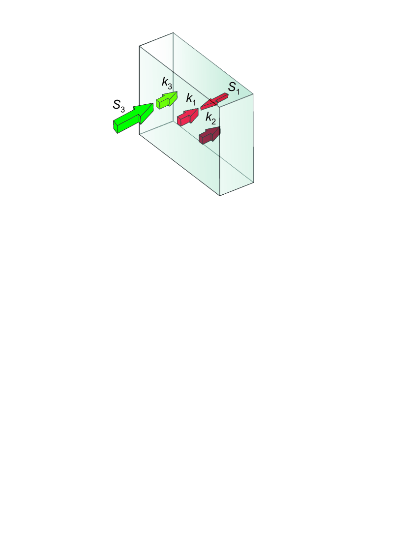
Unusual features of NLO coupling of the ordinary and backward EM waves that enable compensating losses for NI signal through optical parametric amplification (OPA) can be summarized as follows. Usually, plasmonic metamaterials possess NI properties only within a certain frequency band and ordinary, PI properties beyond such a band. Figure 1(a) depicts a slab of thickness with quadratic magnetic NLO response . The medium with quadratic electric response would exhibit similar behavior. A NI (signal) wave at enters the slab at its rear interface and a strong PI control field, at , enters the slab at its front interface. The control field at and weak signal at then generate a difference-frequency idler at which falls in the PI frequency domain. The idler contributes back to the signal through the similar TWM process, , and thus provides OPA of the signal. Such choice of the propagation directions ensures all wave vectors to appear co-directed.
(a) (b)
(c) (d)
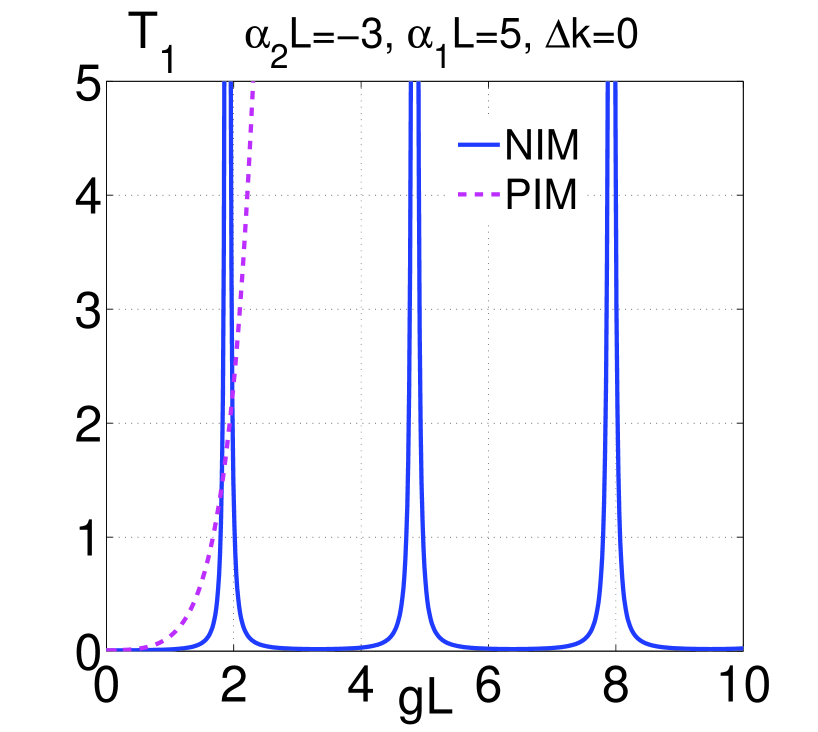
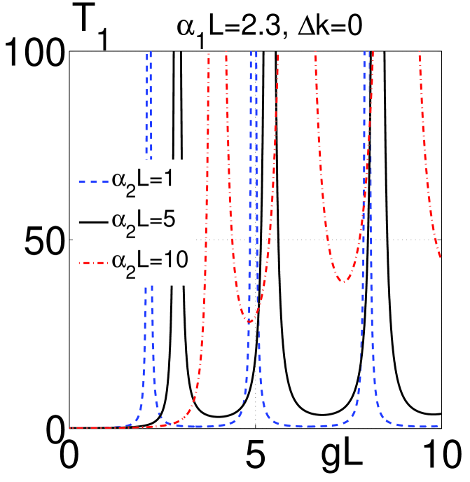
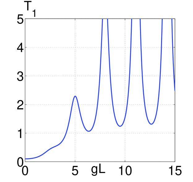
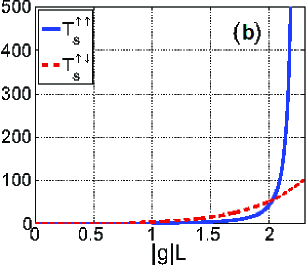
Crucial importance of the outlined geometrical resonances and striking difference of NLO propagation processes in negative index double domain NIM compared with their counterparts in ordinary materials are illustrated in Fig. 1 adopted from our paper SPI . Besides the factor , the local NLO energy conversion rate for the signal is proportional to the amplitude of the idler (and vice versa) and depends on the phase mismatch . Hence, the fact that the waves decay in opposite directions causes a specific, strong dependence of the entire propagation process and, consequently, of the transmission properties of the slab on the ratio of the signal and the idler decay rates. Such extraordinary resonance behavior, which occurs due to the backwardness of the light waves in NIMs, is explicitly seen when compared with similar distribution in ordinary, PI materials depicted in Fig. 1(b). Basically, such induced transparency resonances are narrow, like those depicted in Fig. 1(b) and by the plot in Fig. 1(c) corresponding to . This indicates that the sample remains opaque anywhere beyond the resonance values of the control field and of the sample thickness. Any sharp frequency dependence of nonlinear susceptibility or absorption indices translates into frequency narrow-band filtering. The slab becomes transparent within the broad range of the slab thickness and the control field intensity if the transmission in all of the minimums is about or more than 1. Figures 1(c,d) show the feasibility of achieving robust transparency and amplification in a NIM slab at the signal frequency through a wide range of the control field intensities and slab thicknesses by the appropriate adjustment of the absorption indices . Oscillation amplitudes grow sharply near the resonances, which indicates the possibility of cavity-less self-oscillations. The distribution of the signal and the idler inside the slab would also dramatically change. These simulations prove that, unless optimized, the signal maximum inside the slab may appear much greater than its output value at . Giant enhancement in the resonances indicates that strong absorption of the left-handed, negative-phase wave and of the idler can be turned into transparency, amplification and even into cavity-free self-oscillation. Self-oscillations would provide for the generation of entangled counter-propagating left-handed, , and right-handed, , photons without a cavity. The outlined features can be employed for design of ultracompact optical sensors, selective filters, amplifiers and oscillators generating beams of counterpropagating entangled photons.
II.2 Three Alternative Coupling Schemes – Three Sensing Options
Figure 2 depict three possible options for the phase matched NLO coupling of the ordinary and backward waves.
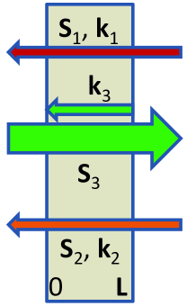
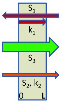
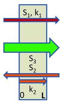
(a) (b) (c)
Consider the example depicted in panel (c). Assume that the wave at with the wave-vector directed along the -axis is a PI () signal. Usually it experiences strong absorption caused by metal inclusions. The medium is supposed to possess a quadratic nonlinearity and is illuminated by the strong higher frequency control field at , which also falls into the PI domain. Due to the three-wave mixing (TWM) interaction, the control and the signal fields generate a difference-frequency idler at , which is a NI wave (). The idler, in cooperation with the control field, contributes back into the wave at through the same type of TWM interaction and thus enables optical parametric amplification (OPA) at and enhanced reflected beam at by converting the energy of the control fields into the signal and the idler. In order to ensure effective energy conversion, the traveling wave of nonlinear polarization of the medium and the coupled electromagnetic wave at the same frequency must be phase matched, i.e., must meet the requirement of . Hence, all phase velocities (wave vectors) must be co-directed. Since , the idler is a BW, i.e., its energy flow appears directed against the -axis. This allows to conveniently remotely interrogate the NLO chip and to actuate amplification and frequency up-conversion of the signal. Transmitted and upconverted waves are sent in the opposite directions towards the remote detectors. Such a signal can be, e.g., infrared thermal radiation emitted by the object of interest, or signal that carries important spectral information about the chemical composition of the environment. The schemes depicted in Fig. 2(a),(b) offer two other options with different operational properties for nonlinear-optical sensing. The research challenge is that such unprecedented NLO coupling schemes lead to changes in the set of coupled nonlinear propagation equations and boundary conditions as compared with the standard ones known from the literature. This, in turn, results in dramatic changes in their solutions and in multiparameter dependencies of the operational properties of the proposed sensor.
III Coherent Nonlinear Optical Coupling of Ordinary and Backward Electromagnetic Waves in Metamaterial made of Carbon Nanotubes
Exciting unparallel avenues for nonlinear electromagnetics can be open by the metamaterials where formation of BWs becomes possible due to specific spatial dispersion of their structural elements. Basic idea is as follows. As outlined above, according to currently commonly adopted concept, negative refractive index and associated backwardness of optical waves require negative permeability and therefore magnetism at optical frequencies. However, a different approach is possible Agr ; AgGa . In a loss-free isotropic medium, energy flux is directed along the group velocity : , . Here, is energy density attributed to EMW. It is seen that the group velocity may become directed against the wavevector depending on sign of dispersion . Basically, negative dispersion can appear in fully dielectric materials with particular dispersion of its structural elements. This opens an entirely novel research and application avenue. In the next subsection, we show a possibility to engineer such a dispersive medium which supports coexistence of both ordinary and BEMWs which can be phase matched. An example of enhanced coherent energy exchange between ordinary fundamental EMW and its second harmonic is considered in a lossless NLO slab for the sake of simplicity.
III.1 Carbon “Nanoforest” and Phase Matching of Ordinary and Backward EM Waves.
Appearance of BEM modes in nanoarrays and layered structures has been predicted recently in Ref. Nef ; Bel ; IgorPRB . Obviously, many other options should have existed. Below, we propose such an option that seems promising in the context of nonlinear propagation and coherent energy conversion processes. Namely, the possibility of conversion of ordinary EMW to the contrapropagating BEMW at its doubled frequency. Hence, such metaslab can be viewed as a frequency-doubling NLO metamirror.
(a)
(b)
(c)
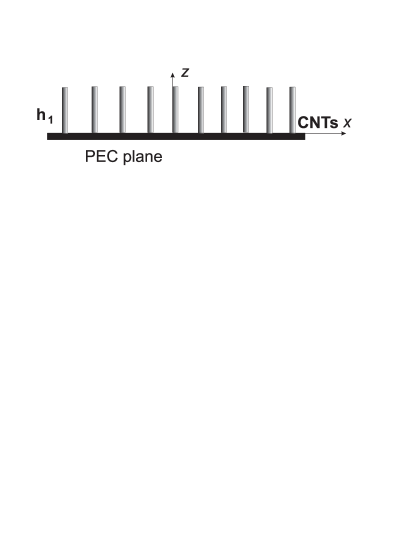
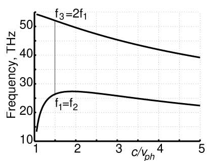
Figure 3(a) depicts a periodic array of carbon nanotubes (CNT) vertically standing on the surface of a perfect electric conductor (PEC) with the CNT ends open to air, which can be seen as perfect magnetic conductor (PMC). As shown in Ref. IgorPRB , EM waves travelling through such CNT “nanoforest,” along x or y directions, posses a hyperbolic dispersion and relatively low losses in the THz and mid-IR ranges. One of the most important consequences from the hyperbolic-type dispersion law is the possibility for propagation of both forward and backward EM waves. Consider EMW propagating along the x-axis. We also introduce group and phase slow-wave factors. The latter one is refractive index. For the given case of surface waves propagating in the slab of CNTs with open ends, whose fields attenuate in air, the dispersion is given by the equation:
| (2) |
Such a dependence can be understood from considering a planar waveguide formed by perfect PEC and PMC planes and tampered with a CNT array. The array axis is orthogonal to the walls of the waveguide. Then, the propagation constant along the waveguide is , where is a positive integer, is the height of the waveguide (CNT) and is the wavenumber in free space. If , BW propagation is allowed when and forbidden for . The relation between the wavevector component and wavenumber is: , where , is the integer determining a number of field variations along CNT, is plasma wavevector. One can show that , if and .
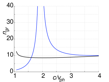
Numerical analysis of Eq. (2) is depicted in Fig. 3(b) for the case of CNT radius nm, the lattice period nm and EM modes with and . Slow-wave factor is proportional to the wave vector: , where is the wave vector in the vacuum. The appearance of positive dispersion for small slow-wave factors is caused by interaction of BW in the CNT slab with the plane wave in air. Indeed, coexistence of the positive (ascending dependence) and negative (descending dependence) dispersion for different frequencies proves that such a metamaterial supports both ordinary and backward EMW. It also proves that resonant plasmonic structures, like split-ring resonators, exhibiting negative and are not the necessary requirement for the realization of BW regime in mid-IR range. The possibility of considerable increased bandwidth of BEMW compared to most plasmonic MM made of nanoscopic resonators is seen that gives the ground to consider CNT arrays as a promising perfect backward-wave metamaterial. The slow-wave factor for both modes is shown in Fig. 3(c). The magnitude of goes to infinity at , which indicates the stop-light regime for the low-frequency mode. Particularly, Fig. 3(b) shows the possibility of phase matching of ordinary fundamental and backward second harmonic EMWs.
III.2 Coherent Energy Exchange Between Short Contrapropagating Pulses in the Carbon Nanoforest
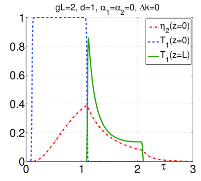
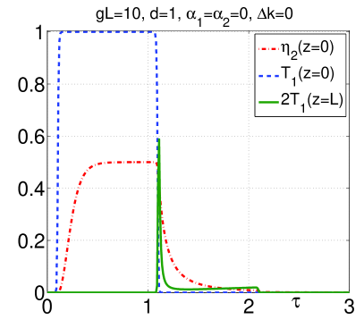
Here, we demonstrate unusual dependence of pulse shape and overall efficiency of SHG on the ratio of input fundamental pulse length and metamaterial slab thickness. Consider a double domain positive/negative index slab of thickness that supports ordinary EMW at fundamental frequency (FH) and BEMW at SH frequency. To ensure phase matching, wavevectors of the FH and SH must be co-directed and, hence, their energy fluxes - counter-directed. The slab operates as a frequency up-converting nonlinear-optical mirror with controllable reflectivity. The equations for amplitudes of FH, , and SH, , can be written as
| (3) | |||
| (4) |
Here, are slowly varying amplitudes proportional to the instant photon numbers in the energy fluxes, are absorption indices, is phase mismatch, and are the group velocities for the corresponding pulses.
(a) (b)
(c) (d)
Note opposite signs in the equations and the requirement of the boundary conditions to be set at the opposite edges of the slab for FH and SH. These lead to cardinal changes in the solutions to the equations as compared to those in the ordinary nonlinear optical material. We have chosen the input pulse shape as being close to a rectangular form
| (5) |
where is the duration of the front and tail, and is the shift of the front relative to . All quantities are reduced by the pulse duration . The magnitudes and have been selected for numerical simulations.
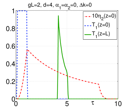
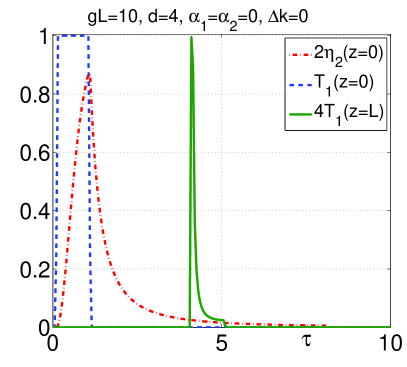
Unusual properties of BWSHG in NIMs in the pulsed regime stem from the fact that it occurs only inside the traveling pulse of FH. SHG begins on its leading edge, grows towards the back edge, and then exits the pulse with no further changes. Since the FH pulse propagates across the slab, the duration of the SH pulse is longer than the fundamental one. Depletion of the FH radiation along the pulse length and the conversion efficiency depend on its initial maximum intensity and phase matching. Ultimately, the overall properties of SHG, such as the pulse length, and the photon conversion efficiency, appear dependent on the ratio of the FH pulse and slab lengths. Such an extraordinary behavior is illustrated in Figs. 4(a)-(d). Here, is the slub thickness reduced by the input pulse length, , is proportional to product of nonlinear susceptibility and the input amplitude of FH. A rectangular shape of the input FH pulse is depicted at when its leading front enters the medium. The results of numerical simulations for the output FH pulse, when its tail passes the slab’s edge at , as well as for the shape and conversion efficiency of the output SH pulse, , when its tail passes the slab’s edge at , are shown. For clarity, here, the medium is assumed loss-free, group velocities of the fundamental and SH pulses assumed equal, . Panels (a) and (b) correspond to the fundamental pulse four time shorter than the slab thickness. Increase of the conversion efficiency with increase of the intensity of the input pulse is seen. It is followed by shortening of the SH pulse. The outlined properties satisfy to the conservation law: the number of annihilated pair of photons of FH radiation ( is equal to the number of output SH photons . Panels (c) and (d) display corresponding changes for a longer input pulse with the length equal to the slab thickness. Here, larger conversion efficiency can be achieved at a lower input intensity compared with the preceding case because of the longer conversion length. The changes in the SH pulse length and conversion efficiency with increase of input intensity appear less significant.
IV Fully Dielectric Backward-Wave NLO Material: Enhancing Coherent Energy Transfer Between Electromagnetic Waves in Ordinary Crystals by Coupling with Optical Phonons with Negative Phase Velocity
As above described, NLO with backward electromagnetic waves enables a great enhancement of energy-conversion rate at the otherwise equal nonlinearities and intensities of input waves. Herein, we propose fundamentally different scheme of TWM of ordinary and backward waves (BW). It builds on the stimulated Raman scattering (SRS) where two ordinary EM waves excite backward elastic vibrational wave in a crystal, which results in TWM. The possibility of such BWs was predicted by L. I. Mandelstam in 1945 Ma , who also had pointed out that negative refraction is a general property of the BWs. The idea underlying the proposed concept and its basic justification is described below. The goal is to show the possibility to replace the NI plasmonic composites, which are challenging to fabricate, with readily available ordinary crystals, some of which have been already extensively studied, and thus to mimic the unparallel properties of coherent NLO energy exchange between the ordinary and BW. The basic idea is as follows. In ph , stimulated Raman scattering (SRS) on optical phonon was investigated in continuous wave (CW) regime. The possibility of distributed-feedback type resonance enhancement of amplification has been shown that stem from negative dispersion of elastic waves. The effect appeared similar to that in three-wave mixing (TWM) of ordinary and BEMWs in NIMs, provided that special requirements are met. Yet, the required intensity of the fundamental field was found to be close to the optical breakdown threshold due to the high phonon damping rate. Here, we show that the indicated fundamental formidable obstacle can be removed by making use of short pulses, which opens the possibility to mimic TWM processes attributed to NIMs in readily available crystals. Besides that, we show that such mixing exhibits unparallel properties that allow for tailoring the shapes of the generated and transmitted pulses and for huge enhancement of the frequency conversion efficiency.
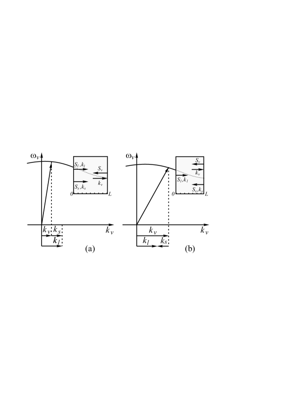
Typical dispersion curve for optical phonons, which exist in crystals containing more than one atom per unit cell, is depicted in Fig. 5. The dispersion is negative in the range from zero to the boundary of the first Brillouin’s zone. Hence, the group velocity of such phonons is antiparallel with respect to its wave-vector . The dispersion can be approximated as . Then, in the vicinity of , velocity is given by , where is the projection of the phase velocity of the vibrational wave on the z-axis and is the dispersion parameter for the given crystal. eq1Optical elastic vibrations can be excited by the light waves through the Raman scattering. The latter gives the ground to consider such a crystal as the analog of the medium with negative refractive index at the phonon frequency and to employ the processes of parametric interaction of three waves, two of which are ordinary EM waves and the third one is the backward wave of elastic vibrations. The coupled waves are described by the equations
| (6) | |||||
| (7) |
Here, , , and are the amplitudes, frequencies and wave-vectors of the fundamental, Stokes and vibrational waves; ; is displacement of the vibrating particles, is the medium density and the requirements , are supposed met. Partial differential equations for the slowly varying amplitudes in the approximation of the first order of in the polarization expansion are Bl :
| (8) | |||||
| (9) | |||||
| (10) |
Here, and are projections of the group velocities of the fundamental, Stokes and vibration waves on the z-axis, is the number density of the vibrating molecules, is the molecule polarizability, is phonon lifetime.
Equations (8)-(10) are similar to those describing TWM of contra-propagating waves in NIMs for the phase-matching scheme of co-propagating fundamental and Stokes waves, where vibration wave counter-directed to the Stokes wave, which is depicted in Fig. 5(a). In the case of continuous waves and neglected depletion of the fundamental wave, resonance enhancement becomes possible, similar to those, depicted in Fig. 1 . On the contrary, only standard exponential behavior is possible in the case of Fig. 5(b). Corresponding transmission factors in the vicinity of first “geometrical” resonance are shown in Fig. 6.
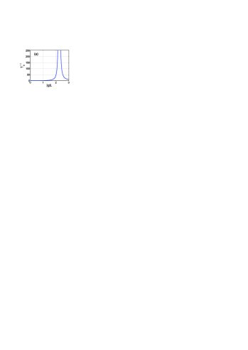
In the resonance, , which is due to the approximation of constant control field. Conversion of the control field to the Stokes one and excited molecule vibrations would lead to saturation of the control field which limits the maximum achievable amplification. Strong amplification in the maximums indicates the possibility of self-oscillations and thus creation of mirrorless optical parametrical oscillator with unparalleled properties. Figures 6(a,b) indicate the possibility to fit in the effective conversion length within the crystal of a given thickness and to significantly concentrate the generated Stokes field nearby its output facet. Such atypical extraordinary behavior in readily available crystals may find exciting applications. However, the estimates have shown that intensity of the fundamental field which is to attain such extraordinary amplification appears close to the optical breakdown threshold ph . It is because of fast phonon damping and corresponding high rate of energy conversion of the fundamental beam in heat.
Below, we show that such seemingly unavoidable obstacles can be overcome in short pulse regime. For the sake of simplicity, we consider model of a rectangular pulse of input fundamental radiation with the pulse duration . A seeding Stokes wave is assumed a weak continuous wave. In the moving coordinate frame associated with this pulse and within its range, complex amplitudes of two other interacting fields become time independent. Then the analytical solution to the equations can be found for amplification corresponding to negligible depletion of the pump due to the conversion. Numerical solution is found for the opposite case. Inside the crystal, the boundary conditions must be fulfilled not at the boundaries of the medium but at the boundaries of the fundamental pulse. The latter is correct for the period of time after the instant when the generated Stokes and vibration pulses reach the boundaries of the fundamental pulse. Such approximation becomes true after travailing a distance , where , and , is length of the fundamental pulse. Hereinafter, the waves are referred to as co-propagating if the Poynting vector of the Stokes wave is co-directed with that of fundamental wave [Fig. 5(a)], and as counter-propagating in the opposite case [Fig. 5(b)]. Note, that is negative for contra-propagating Stokes wave.
In the approximation of constant pump amplitude, in the coordinate frame locked to the pump pulse, and within the pulse, equations for the generated Stokes and backward vibration waves take the form:
| (11) |
Here, , is the phonon mean free path, , , , ; for co-propagating and for counter-propagating beams. Since the Stokes frequency is less than that of the fundamental one, and .
Equations (11) are similar to those describing CW TWM, ph except the boundary conditions. They correctly describe possible huge amplification of the Stokes signal until relatively small part of the strong input laser beam is converted. For co-directed laser and Stokes waves, the boundary conditions are:
| (12) |
In the opposite case, they are written as
| (13) |
The analysis of solution to Eqs. (11) shows that, in the given approximation of neglected depletion of the fundamental wave, amplification of co-directed signal tends to infinity, when the pulse energy approaches the resonance value corresponding to , where . This indicates the possibility of huge enhancement of the conversion efficiency. Respective intensity of the fundamental field is given by the equation
| (14) |
where, is refractive index at and is the wavelength in vacuum. From comparison with the corresponding value for the CW regime ph , one concludes
| (15) |
For the crystal parameters, which are characteristic for calcite Alf and diamond G ; An ; Chen , Eq. (15) yields and, hence, suggests a decreases of down to W/cm2. The latter is achievable with commercial femtosecond lasers and falls below the optical breakdown threshold for most transparent crystals.
Equation (15) displays two factors that determine substantial decrease of in pulsed regime compared to that in CW one. First factor is the ratio of group velocity of the elastic wave to that of the fundamental one, , which is on the order of . This factor is attributed to the fact that phonons generated on the front edge of the laser pulse propagate in the opposite direction and, hence, exit very fast, practically with the optical group velocity, from the fundamental pulse zone before it is dissipated. Hence, effective phonon mean free pass becomes commensurable with the fundamental pulse length. This mitigates the detrimental effect of phonon damping. With increase of , phonon mean free path grows, which decreases both and in a way that the advantage of pulse regime over CW regime diminishes. The second factor in Eq. (15) determines further decrease of due to small optical dispersion in the transparency region of the crystals. The fact that the Stokes pulse surpasses the fundamental one slowly increases significantly the effective NLO coupling length.
To investigate the regimes of significant energy conversion, a set of partial differential Eqs. (8)-(10) was solved numerically in three steps: TWM in the vicinity of the entrance, inside and in the vicinity of the exit from the Raman slab. Simulations for the first and third intervals were made in the laboratory reference frame with the boundary conditions applied to the corresponding edges of the slab. The propagation process inside the slab was simulated in the moving frame of reference with the boundary conditions applied to the pulse edges. Such an approach allowed for significant reduction of the computation time because, for each given instant, the integration was required only through the space interval inside the fundamental pulse and not through the entire medium. Shape of the fundamental pulse was chosen nearly rectangular and symmetric with respect to its center
The slope , the pulse duration at half-maximum and its delay were scaled to the fundamental pulse width . The amplitude of input CW Stokes signal was chosen . Numerical investigations were done for the model with parameters typical for calcite Alf ( cm-1) and diamond G ; An ; Chen ( cm-1): carrying wavelength nm, pulse duration fs, cm-1, , cm/s, cm/s, cm/s for co-propagating and cm/s for counter-propagating waves, (g/cm)1/2, the crystal length L=1cm.
(a) (b)
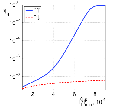
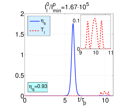
Figure 7(a) displays the output quantum conversion efficiency vs. input pulse intensity, both for co-propagating () and counter-propagating () geometries. Many orders increase of the conversion efficiency due to BW effect in the case of co-propagating waves is explicitly seen. Saturation at is due to depletion of fundamental radiation caused by conversion to Stokes radiation. Figure 7(b) displays a shortened Stokes output pulse that has surpassed the inhomogeneously depleted and broadened fundamental pulse (zoomed in the inset).
(a) (b)
(c) (d)
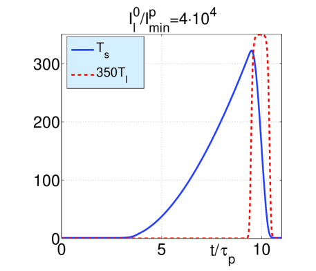
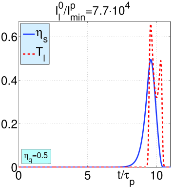
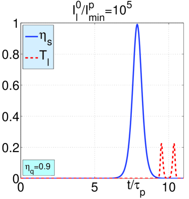
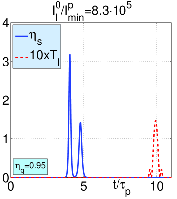
The simulations also show that shapes of the output Stokes and fundamental pulses differ and vary significantly depending on the intensity of the input fundamental wave. Figure 8(a) depicts amplified output pulse of Stokes radiation for relatively small depletion due to conversion of the fundamental beam. Here, shape of the fundamental pulse is unchanged. The shape of the amplified Stokes pulse is different and determined by the fact that and Stokes pulse has surpassed the fundamental one. In contrast, the quantum conversion becomes significant in Figs. 8(b)-(d). Corresponding depletion of the output fundamental pulse and changes in its shape are explicitly seen. Note that in the case depicted in Fig. 8(d), the output Stokes pulse significantly overtakes the pump pulse. In the latter case, major conversion occurred inside, far from the crystal edges, and then both pulses propagated without interaction. It is seen that output Stokes pulse narrows with the increase of energy of the fundamental pulse. Here, crystal length of 1cm fits L/lp = 1357 input pulse lengths. The threshold intensity W/cm2 corresponds to 60 fs pulse of about 5 J energy focused to the spot of diameter D = 100 m. Intensity of the seeding Stokes signal was chosen .
Note, that the described NLO propagation process is in a striking contrast with their positive group velocity counterparts ShB ; Boy , including acoustic waves with energy fluxes directed against that of EM waves Bob . The proposed here concept is different from the one earlier proposed in Har and does not require periodic poling of quadratic nonlinear susceptibility of crystals at the nanoscale as described in Kh (and in the references therein).
V Conclusion
The possibility of creation of remotely all-optical controlled frequency up-converting and amplifying nonlinear optical sensor (image and data processing chips) is investigated and proved with numerical simulations. Novel photonic materials are proposed which support coexistence of ordinary and backward waves that can be phase matched. Such nonlinear-optical materials enable greatly enhanced nonlinear-optical frequency-conversion processes that can be employed for creation of optical sensors with unparallel operational properties. Two different classes of such materials are proposed: metamaterials with specially engineered spatial dispersion and crystals that support optical phonons with negative phase velocity. Unlike current mainstream in fabricating negative index metamaterials, both options do not rely on nanoresonators that provide negative optical magnetism and thus constitute current mainstream in fabricating negative index metamaterials. Extraordinary properties of coherent frequency conversion processes in the proposed materials are numerically simulated both in continuous wave and in short pulse regimes.
As an example of dispersion engineering, a metamaterial made of standing carbon nanotubes is described which supports coexistence of ordinary fundamental and backward second harmonic electromagnetic waves that can be phase matched. Extraordinary properties of such frequency-doubling metamirror operating in short-pulse regime appear in striking contrasts with second harmonic generation in ordinary materials.
Fabrication of specially shaped nanostructures which enable negative optical magnetism is challenging task that relies on sophisticated methods of nanotechnology. Engineering a strong fast quadratic NLO response by such mesoatoms also presents a challenging goal not yet achieved. This work proposes a different paradigm, which is to mimic similar extraordinary backward-wave frequency conversion processes through making use of readily available Raman active crystals. Basic underpinning idea is to replace one of the coupled backward optical electromagnetic mode, which existence is commonly attributed to negative-index metamaterials, by optical phonons - the elastic wave with negative group velocity. Operation in short pulse regime is proposed to remove a severe detrimental factor imposed by fast phonon damping. Significant decrease of the required minimum intensity of fundamental radiation, as compared with that in the continuous-wave regime, is predicted down to that provided by commercial lasers. Unparallel properties of the proposed short-pulse process are numerically simulated and the possibility of huge enhancement of quantum conversion efficiency as well as of tailoring duration and shapes of the generated and transmitted fundamental pulses are predicted.
Further elaboration of the proposed concept allows to utilize the revealed extraordinary features for creation of a family of unique photonic devices with advanced functional properties such as nonlinear-optical mirrors with frequency-dependent controllable reflectivity, unidirectional optical amplifiers, frequency narrow band filters, switches and cavity-free optical parametric oscillators, which can be exploited for optical sensing. There exist many dispersive materials and readily available Raman-active transparent crystals that support electromagnetic and elastic waves with negative group velocity which can be utilized for the given purpose. Some of them may offer the opportunities for further optimization of unparallel operational characteristics of the proposed photonic devices.
VI Acknowledgments
This work was supported in parts by the Air Force Office of Scientific Research (Contract No FA950-12-1-298), by the National Science Foundation (Grant No ECCS-1028353), by the Academy of Finland and Nokia through the Center-of- Excellence program, by the Presidium of the Russian Academy of Sciences (Grant No 24-31), and by the Russian Federal Program on Science, Education and In- novation ( Grant No 14.A18.21.1942).
References
- (1) Popov, A.K., “Frequency-tunable nonlinear-optical negative-index metamirror for sensing applications”, Proc. SPIE 8034, Photonic Microdevices/Microstructures for Sensing III, 80340L (May 16, 2011); doi:10.1117/12.884127.
- (2) Popov, A. K., “Nonlinear optics of backward waves and extraordinary features of plasmonic nonlinear-optical microdevices,” Eur. Phys. J. D 58, 263–274 (2010).
- (3) Popov, A. K., and Shalaev, V. M., “Merging nonlinear optics and negative-index metamaterials,” Proc. SPIE 8093, Metamaterials: Fundamentals and Applications IV, 809306 (September 09, 2011); doi:10.1117/12.896526; arXiv:1108.0867.
- (4) Shadrivov, I. V., Zharov, A. A. and Kivshar, Y. S., “Second-harmonic generation in nonlinear left-handed metamaterials,” J. Opt. Soc. Am. B 23, 529–534 (2006).
- (5) Scalora, M., D’Aguanno, G., Bloemer, M., Centini, M., Mattiucci, N., de Ceglia, D. and Kivshar, Yu. S., “Dynamics of short pulses and phase matched second harmonic generation in negative index materials, Opt. Express 14, 4746–4756 (2006).
- (6) Popov, A. K., Slabko, V. V. and Shalaev, V.M., “Second harmonic generation in left-handed metamaterials,” Laser Phys. Lett 3, 293–297 (2006).
- (7) Popov, A. K. and Shalaev, V. M., “Compensating losses in negative-index metamaterials by optical parametric amplification,” Opt. Lett., 31, 2169–2171 (2006).
- (8) Elyutin, S. O., Maimistov, A. I. and Gabitov, I. R., “On the third harmonic generation in a medium with negative pump wave refraction,” JETP 111, 157–169 (2010).
- (9) Popov, A. K. and George, T. F., “Computational studies of tailored negative-index metamaterials and microdevices,” Chapter 13, in [ Computational Studies of New Materials II: From Ultrafast Processes and Nanostructures to Optoelectronics, Energy Storage and Nanomedicine], Edited by T. F. George, D. Jelski, R. R. Letfullin, and G. Zhang, World Scientific, Singapore (2011).
- (10) Popov, A. K., Myslivets, S. A., and Shalaev, V.M., “Plasmonics: nonlinear optics, negative phase, and transformable transparency,” Proc. SPIE 7395, Plasmonics: Nanoimaging, Nanofabrication, and their Applications V, 73950Z (September 02, 2009); doi:10.1117/12.824836.
- (11) Agranovich, V. M., Shen, Y. R., Baughman, R. H., and Zakhidov, A. A., “Linear and Nonlinear Wave Propagation in Negative Refraction Metamaterials,” Phys. Rev. B 69, 165112 (2004).
- (12) Agranovich, V. M., Gartstein, Yu. N., “Spatial dispersion and negative refraction of light,” Physics-Uspekhi (UFN) 176, 1051- 1068 (2006) (Also in [Physics of Negative Refraction] (Eds C.M. Krowne, Y. Zhang) (Springer, 2007).
- (13) Nefedov, I., and Tretyakov, S., “Ultrabroadband electromagnetically indefinite medium formed by aligned carbon nanotubes,” Pys. Rev. B 84, 113410-4 (2011).
- (14) Belov, P. A., Orlov, A. A., Chebykin, A. V., and Kivshar, Yu. S., “Spatial dispersion in layered metamaterials,” Proc. of The International Conference on Electrodynamics of complex Materials for Advanced Technologies PLASMETA’11, September 21-26, Samarkand, Uzbekistan, 30-31 (2011).
- (15) Nefedov, I. S., “Electromagnetic waves propagating in a periodic array of parallel metallic carbon nanotubes,” Phys. Rev. B 82, 155423(7) (2010).
- (16) Mandelstam, L. I., “Group velocity in a crystall lattice,” ZhETF 15, 475–478 (1945) [in Russian].
- (17) Shalaev, M. I., Myslivets, S. A., Slabko, V. V., and Popov, A. K., “Negative group velocity and three-wave mixing in dielectric crystals,” Opt. Lett. 36, 3861–3863 (2011).
- (18) Bloembergen, N., [Nonlinear Optics], W. A. Benjamin, Inc., New York, 1965, Ch. 4.
- (19) Alfano, R. R. and Shapiro, S. I., “Optical Phonon Lifetime Measured Directly with Picosecond Pulses,” Phys. Rev. Lett. 26, 1247–1250 (1971).
- (20) Gorelik, V. S., [Contemporary problems of Raman spectroscopy (in Russian)], Moscow, Nauka Publishing Co., 28–47 (1978).
- (21) Anastassakis, E., Iwasa, S., and Burstein, E., “Electric-Field-Induced Infrared Absorption In Diamond,” Phys. Rev. Lett. 17, 1051–1054 (1966).
- (22) Chen , Y., and Lee, J. D., “Determining material constants in micromorphic theory through phonon dispersion relations,” International J. of Engineering Science 41, 871–886 (2003).
- (23) Shen, Y. R., and Bloembergen, N., “Theory of stimulated brillouin and raman scattering,” Phys. Rev. 137, A1787–A1805 (1965).
- (24) Boyd, R. W., [Nonlinear Optics], Third Edition, Amsterdam: Academic Press, (2008).
- (25) Bobroff, D. L., “Coupled-modes analysis of the phonon-photon parametric backward-wave oscillator,” J. Appl. Phys. 36, 1760–1769 (1965).
- (26) Harris, S. E., “Proposed backward wave oscillations in the infrared,” Appl. Phys. Lett. 9, 114–117 (1966).
- (27) Khurgin, J. B., “Mirrorless magic,” Nat. Photonics 1, 446–448 (2007).