Arrayed Continuous-wave THz Photomixers
Abstract
We present both chip-scale and free space coherent arrays of continuous-wave THz photomixers. By altering the relative phases of the exciting laser signals, the relative THz phase between the array elements can be tuned, allowing for beam steering. The constructive interference of the emission of elements leads to an increase of the focal intensity by a factor of while reducing the beam width by , below the diffraction limit of a single source. Such array architectures strongly improve the THz power distribution for stand-off spectroscopy and imaging systems while providing a huge bandwidth at the same time. We demonstrate this by beam profiles generated by a free space 22 and a 41 array for a transmission distance of 4.2 meters. Spectra between 70 GHz and 1.1 THz have been recorded with these arrays.
Applications of Terahertz (THz, 100 GHz-10 THz) radiation in spectroscopy, security and imaging have gained strong interest in recent years due to the unique properties of matter and radiation in this spectral range. Many gases and substances show very narrow, unique spectral absorption features that allow for unambiguous identification Brown . THz spectra even allow for identifying different isotopologues of the same chemical compound D2O . Furthermore, THz radiation penetrates through common clothing and can reveal hidden objects underneath, even non-metallic threats ZhangSecurity ; Explosives . These properties are very attractive for security demands, particularly in terms of detection of explosives and drugs. Such applications, however, require both sensitive and fast detectors and powerful emitters. Different emitter concepts like frequency multiplied Gunn- or IMPATT-diodes Gunn1p7-1p9 , quantum cascade lasers QCL_lowf , Josephson junction superlattices LutfiSupST or backward wave oscillators BWOImaging04 have already been realized, but they are often limited in their tunability or require a cryogenic environment. For accessing a large frequency range, photomixing MeinReview ; RubenEL ; APL1 ; ITO_SST ; Book_THzGeneral is the method of choice, covering several octaves with a single setup at room temperature. In most cases, pulsed time domain systems GasMittleman98 ; Sartorius08 ; Schall_Helm_Keiding are used since they provide very high output power levels DekorsyNeu ; MeinLAE with up to a few mW average THz power. Continuous-wave (CW) systems operating with a single device are yet limited to the W range at 1 THz ITO_SST ; RenaudSeedsHighP .
A possible way to overcome the output power limitation of a single CW emitter utilizes a phased antenna array of individual, mutually coherent sources. Focal plane arrays focalPlaneArray are already used in the THz and sub-THz frequency range mmWTHzimaging for detection in both passive and active imaging. Phased emitter arrays are described in RF and microwave theory and are frequently used as directive elements to transmit electromagnetic radiation. In a similar manner, phase coherent THz sources can be set up in an array configuration and even be integrated on a chip ImagingArray ; Integrated .
In this paper, we show two versions of such an array: first, we show an on-chip array consisting of low-temperature grown GaAs (LT-GaAs) photoconductive mixers. Second, we show a free space array of individually packaged n-i-pn-i-p superlattice photomixers APL1 ; MeinReview . We discuss the advantages of both continuous-wave setups. All experiments were carried out at room temperature.
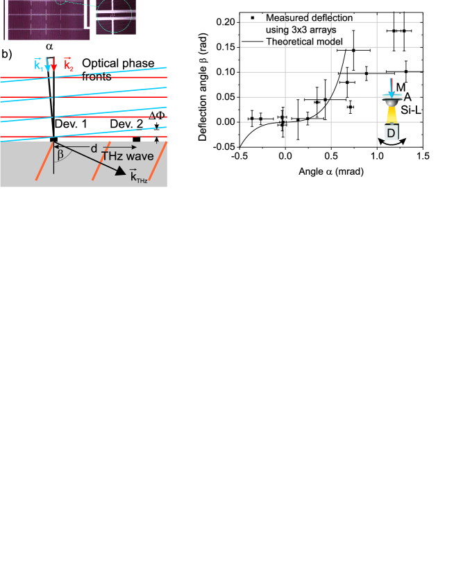
The on-chip version is illustrated in Fig. 1 a. It consists of LT-GaAs photoconductive switches with a finger electrode geometry (gap: 2m, width 1m, total area: 1010 m2) and resonant dipole antennas SPIE06 . The emitters are arrayed in a 33 configuration. DC bias lines connect the emitters. Two Ti-sapphire lasers, at frequencies and are heterodyned in order to provide a THz beat note at the difference frequency, . In order to adjust the THz phase between the emitters, we allow for a small angle, between the two free space laser beams (see Fig. 1 b). The total laser intensity becomes
| (1) |
where is a spatially varying phase due to the inclination of the laser beams; is the (angular) THz frequency, and are the wave vectors of the optical laser beams. is an (arbitrary) overall phase between the two laser signals, which can be chosen zero. The relative THz phase of two photomixers that are separated by a distance, , is
| (2) |
where the anlges refer to the angle between the laser beam and the surface normal. For simplicity, one beam incidence is chosen perpendicular to the device, i.e. and is the inclination angle of the other laser beam as shown in Fig. 1 b). This results in a phase difference of , where is the laser wavelength ( 850 nm). The THz phase is therefore “amplified” by the ratio of laser wavelength and the emitter spacing, , which is roughly a factor of 1000. Very small angles between the two heterodyned lasers are sufficient to achieve a large phase shift of the emitted THz beam. For example, an angle of is sufficient to achieve a phase shift for an emitter pitch of 250 m and a laser wavelength of 850 nm, as used in this experiment. For equidistant devices in the array, the single parameter is sufficient to adjust all phases correctly for coherent emission in one direction. This allows for rapid scanning of the THz beam by a small angular offset between the optical beams. The challenge of on-chip arrays is the distribution of the optical power on the individual elements, since the active device area ( m2) is only a very small fraction of the illuminated array area ( mm2). A microlens array, adapted to the pitch of 250 m is therefore used to distribute the heterodyned laser signals. For outcoupling of the THz beam, a hyperhemispherical silicon lens with a diameter of 10 mm was used. The lens focuses the THz beam due to the hyperhemisphericity. Both spherical aberrations and the focusing properties decrease the total deflection angle. Fig. 1 c) shows the deflection of the THz beam vs. inclination angle between the optical beams, , for 33 arrays with a pitch of m, demonstrating the steerability of the THz beam.
On the one hand, integrating photomixers on a single chip bears the advantages of small size and the integratability with a silicon lens. For large arrays with a huge number of elements, however, a silicon lens may not be necessary at all, since a high directivity ensures efficient outcoupling through the backside of the chip QuiqueGo . On the other hand, the distribution of the optical power on the very small sized photomixers (typically m2) requires careful alignment. Furthermore, cross-talk between the arrayed antennas is inevitable: Chip-integrated antenna elements are typically spaced on the same scale as the THz-wavelength. In addition, semiconductor based THz photomixer sources require electrical biasing that has to be integrated in the layout. The design of integrated arrays requires simulations. Optimum performance is typically only achievable in a narrow bandwidth and steerability is limited since phase shifts between devices affect the cross talk. Broadband operation with reduced cross talk would require larger spacing between the elements. If the array elements are too loosely spaced, the side lobes will gain strength QuiqueGo .
Another possibility to gain directivity and brightness is an array of mutually coherent free space sources, each with relatively small aperture. Fig. 2 shows a typical setup. There is no RF cross-talk since the emitters can be electrically isolated from each other. Both large bandwidth and high power are achieveable. Furthermore, the mutual coherence results in an interference pattern which can be optimized for small spot sizes at stand-off distances. Similar to the on-chip array, all photomixers are driven by the same pair of lasers. This assures the mutual coherence.
A small phase offset between the emitters allows for steering the spot without mechanical tilting, similar to the on-chip array. Here, the phase offset is simply achieved by delaying the photomixing laser signal for the individual emitters by a fraction of the THz wavelength. Furthermore, the mutual coherence of in-phase emitters, each with its own focusing optics, generates an intense central spot in the target plane. The peak intensity of an element array is higher than that generated by a single device SPIE08 . At the same time, the beam waist is reduced by , where the parameter takes the spacing and aperture size of the sources into account. For a linear array with equidistant emitters spaced by a distance, , as illustrated in Fig. 2 a), and focused to a target at a distance, , the interference of the individual beams generates an intense peak with a FWHM (full width half maximum) along the emitter axis of
| (3) |
The ideal diffraction-limited FWHM beam diameter of a single emitter in the target plane is
| (4) |
which is calculated by convoluting the emitted Gaussian beam with the circular aperture of the focusing lens (radius ). Dividing eq. 4 by eq. 3 yields for the parameter . is only dependent on the ratio of the source separation and the aperture diameter ().
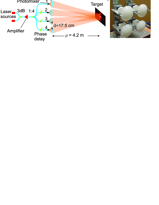
The photomixers used for the free space array are telecom-wavelength compatible n-i-pn-i-p superlattice photomixers MeinReview ; APL1 . They are operated with fiber-coupled 1550 nm lasers that are amplified by an erbium-doped fiber amplifier. The amplified light is split up and distributed in the array in an all-polarization maintaining fiber setup. Care is taken to ensure the same optical path length of all devices. The photomixers are equipped with broadband logarithmic-periodic antennas with an operation range from 60 GHz to 2 THz and mounted on a hyperhemispherical silicon lens with a diameter of 10 mm. The generated THz beams are pre-shaped by a pair of aspherical polyethylene lenses (aperture diameter cm of the focusing lens) in order to collimate the beam. The emitters are spaced by 17.5 cm in a 41 or a 22 array. The individual THz beams are combined and interfered at a distance of 4.2 m. We first examine the scaling law of eq. 3 using a linear array with up to 4 sources. The recorded cross sections of the beam patterns in the target plane along the array axis for 1-4 emitters are shown in Fig. 3 a) for a frequency of 0.23 THz. The measured peak width for these interference patterns are shown in table 1. The expected values from eq. (3), (4) are also shown for comparison. The measured scaling factor of is in very good agreement with the expected value of 1.6.

The data were obtained using a Golay cell detector with an aperture diameter of 6 mm. No focusing optics was used. The measured peaks are a convolution of the Golay cell aperture and the THz beam. The FWHM is therefore larger than prediced by theory. For 4 sources, the measured beam waist along the array axis is only 7.9 mm. This is well below the diffraction limit of a single device that features a FWHM beam waist of 47 mm. The same effect was verified at 0.81 THz. A slit aperture (width 2.25 mm) was used to scan the peak. A FWHM of 2.7 mm was recorded with 4 sources, again in the range of the slit size. The theoretical beam waist is 2 mm at this frequency.
The position of the central interference peak can be shifted within the envelope of the beam pattern of a single emitter by adjusting the relative phase of the individual photomixers. The strength of the zeroth order interference peak follows the envelope of the single source, resulting in reduced intensity for large shifts. Furthermore, higher interference orders (side lobes) gain strength once they approach the maximum of the single source beam pattern. The scan range should therefore be restricted to SPIESeb .
| # of emitters | (mm) | (mm) |
| 1 | 47 | 48 |
| 2 | 15 | 14 |
| 3 | 10 | 9.4 |
| 4 | 7.9 | 7.0 |
Fig. 3 b) shows a frequency sweep of the 41 array and of a single emitter measured with a Golay cell at 4.2 m distance in the laboratory without any additional focusing optics. The increase in intensity of almost a factor of persists over the whole frequency range. Water absorption lines are clearly visible.
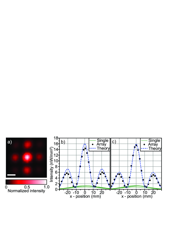
Fig. 4 a) shows the beam pattern of the 22 array at 0.4 THz. Fig. 4 b) and c) show the cross sections of the interference pattern at 0.32 THz. The intensity of the zeroth order (central peak) is almost times higher than that of an individual photomixer. The beam waist of the central peak of 11 mm is by a factor of 3.7 smaller than that of a single device (41 mm). Due to the small number of array elements, the side lobes are still very pronounced. They can be reduced by using more array elements. The side lobes along the array axis were suppressed by a factor of 2.4. The agreement between the theoretical expectation and the experiment is excellent.
In conclusion, we characterized on-chip arrays and free space arrays of THz photomixers. On-chip arrays are of small size and allow for integratability at the cost of bandwidth due to cross talk. Free space arrays offer large bandwidth and tunability, small spot size () at stand-off distances due to interference effects and high focal intensity () while using relatively small optics. The diameter of the interference peak for a linear array at a distance of 4.2 m was more than 5 times smaller than that of a single emitter using 12 cm optics. Both array concepts allow for steering the THz beam by controlling the phases of the optical beams illuminating the array elements. This was demonstrated with the on-chip array by implementing a tilted phase front of the heterodyned laser beams. Fiber delay stages could be used for the fiber-coupled free space array for beam scanning. The advantages of both free space and chip-scale arrays could be combined by implementing broadband antennas in an on-chip array. The individual photomixers could be fiber-coupled, providing a high power, tunable, and miniaturized cw THz source.
References
- (1) A. S. Pine, R. D. Suenram, E. R. Brown, and K. A. McIntosh, “A Terahertz Photomixing Spectrometer: Application to SO2 Self Broadening,” J. Mol. Spectroscopy 175, 37–47 (1996)
- (2) S. Brünken, H. S. P. Müller, C. Endres, F. Lewen, T. Giesen, B. Drouin, J. C. Pearson, and H. Mäder, “High resolution rotational spectroscopy on D2O up to 2.7 THz in its ground and first excited vibrational bending states,” Phys. Chem. Chem. Phys. 9, 2103–2112 (2007).
- (3) H.-B. Liu, H. Zhong, N. Karpowicz, Y. Chen, and X.-C. Zhang, “Terahertz spectroscopy and imaging for defense and security applications,” Proc. of IEEE 95, 1514–1527 (2007).
- (4) M. J. Fitsch, D. Schauki, C. Dodson, and R. Osiander, “THz spectroscopy of explosives and related compounds,” Proc. SPIE 5411, 84–91 (2004).
- (5) A. Maestrini, J. Ward, J. Gill, H. Javadi, E. Schlecht, G. Chattopadhyay, F. Maiwald, N. R. Erickson, and I. Mehdi, “A 1.7 -1.9 THz local oscillator source,” IEEE Microw. Wirel. Compon. Lett. 14, 253–255 (2004).
- (6) C. Walther, M. Fischer, G. Scalari, R. Terazzi, N. Holyer, and J. Faist, “Quantum cascade lasers operation from 1.2 to 1.6 THz,” Appl. Phys. Lett. 91, 131122 (2007).
- (7) F. Turkoglu, H. Koseoglu, Y. Demirhan, L. Ozyuzer, S. Preu, S. Malzer, Y. Simsek, P. Müller, T. Yamamoto, and K. Kadowaki, “Interferometer measurements of terahertz waves from bi2sr2cacu2o8+δ mesas,” Supercond. Sci. Technol. 25, 125004 (2012).
- (8) A. Dobroiu, M. Yamashita, Y. N. Ohshima, Y. Morita, C. Otani, and K. Kawase, “Terahertz imaging system based on a backward-wave oscillator,” Appl. Opt. 43, 5637–5646 (2004).
- (9) S. Preu, G. H. Döhler, S. Malzer, L. Wang, and A. C. Gossard, “Tunable, continuous-wave Terahertz photomixer sources and applications,” J. Appl. Phys. 109, 061301 (2011).
- (10) A. R. Criado, C. de Dios, G. H. Döhler, S. Preu, S. Malzer, S. Bauerschmidt, H. Lu, A. C. Gossard, and P. Acedo, “Ultra-narrow linewidth cw sub-THz generation using gs based ofcg and n-i-pn-i-p superlattice photomixers,” Electron. Lett. 48, 1425–1426 (2012).
- (11) S. Preu, F. H. Renner, S. Malzer, G. H. Döhler, L. J. Wang, T. L. J. Wilkinson, E. R. Brown, M. Hanson, and A. C. Gossard, “Efficient terahertz emission from ballistic transport enhanced n-i-p-n-i-p superlattice photomixers,” Appl. Phys. Lett. 90, 212115 (2007).
- (12) H.Ito, F. Nakajima, T. Futura, and T. Ishibashi, “Continuous THz-wave generation using antenna-integrated uni-travelling-carrier photodiodes,” Semicond. Sci. Technol. 20, 191–198 (2005).
- (13) Y.-S. Lee, Principles of Terahertz Science and Technology (Springer, 2009).
- (14) D. M. Mittleman, R. H. Jacobsen, R. Neelamani, R. G. Baraniuk, and M. C. Nuss, “Gas sensing using Terahertz time-domain spectroscopy,” Appl. Phys. B 67, 379–390 (1998).
- (15) B. Sartorius, H. Roehle, H. Künzel, J. Böttcher, M. Schlak, D. Stanze, H. Venghaus, and M. Schell, “All-fiber Terahertz time-domain spectrometer operating at 1.5 m telecom wavelengths,” Opt. Expr. 16, 9565–9570 (2008).
- (16) M. Schall, H. Helm, and S. R. Keiding, “Far infrared properties of electro-optic crystals measured by THz time-domain spectroscopy,” Int. J. Infrared and mm waves 20, 595–604 (1999).
- (17) M. Beck, H. Schäfer, G. Klatt, J. Demsar, S. Winnerl, M. Helm, and T. Dekorsy, “Impulsive Terahertz radiation with high electric fields from an amplifier-driven large-area photoconductive antenna,” Opt. Express 18, 9251–9257 (2010).
- (18) S. Preu, M. Mittendorff, H. Lu, H. Weber, S. Winnerl, and A. Gossard, “1550 nm eras:In(Al)GaAs large area photoconductive emitters,” Appl. Phys. Lett. 101, 101105 (2012).
- (19) C. C. Renaud, M. Robertson, D. Rogers, R. Firth, P. J. Cannard, R. Moore, and A. J. Seeds, “A high responsivity, broadband waveguide uni-travelling carrier photodiode,” Proc. SPIE 6194, 6164C (2006).
- (20) A. W. M. Lee, B. S. Williams, S. Kumar, Q. Hu, and J. L. Reno, “Real-time imaging using 4.3-THz quantum cascade laser and a 320 240 microbolometer focal-plane array,” IEEE Photon. Technol. Lett. 18, 1415–1417 (2006).
- (21) R. Appleby, “Passive millimeter-wave imaging and how it differs from terahertz imaging,” Phil. Trans. R. Soc. Lond. A, 379–394 (2004).
- (22) J. F. Federici, D. Gary, B. Schulkin, F. Huang, H. Altan, R. Barat, and D. Zimdars, “Terahertz imaging using an interferometric array,” Appl. Phys. Lett. 83, 2477 (2003).
- (23) N. Shimizu and T. Nagatsuma, “Photodiode-integrated microstrip anenna array for subterahertz radiation,” IEEE Photon. Technol. Lett. 18, 2006 (743-745).
- (24) S. Preu, S. Malzer, G. H. Döhler, J. Zhang, Z. H. Lu, and L. J. Wang, “Highly collimated and directional continuous-wave terahertz emission by photomixing in semiconductor device arrays,” SPIE 6194, 13 (2006).
- (25) A. Rivera-Lavado, L. E. Garcia-Munoz, G. Döhler, S. Malzer, S. Preu, S. Bauerschmidt, J. M. de Paz, E. Ugarte-Munoz, B. Andres-Garcia, V. Izquierdo-Bermudez, and D. Sergovia-Vargas, “Arrays and new antenna topologies for increasing THz power generation using photomixers,” J. Infrared Milli Terahz Waves 34, 97–108 (2013).
- (26) S. Preu, S. Malzer, G. H. Döhler, and L. J. Wang, “Coherent superposition of terahertz beams,” Proc. SPIE 7117, 28 (2008).
- (27) S. Bauerschmidt, S. Preu, S. Malzer, G. Döhler, L. Wang, H. Lu, and A. Gossard, “Continuous wave terahertz emitter arrays for spectroscopy and imaging,” Proc. of SPIE 7671, 76710D (2010).