Phonon excitation and instabilities in biased graphene nanoconstrictions
Abstract
We calculate the phonons in a graphene nanoconstriction(GNC) in the presence of a high current density. The Joule-heating, current-induced forces, and coupling to electrode phonons is evaluated using first principles nonequilibrium DFT-NEGF calculations. Close to a resonance in the electronic structure we observe a strongly nonlinear heating with bias and breakdown of the harmonic approximation. This behavior results from negatively damped phonons driven by the current. The effect may limit the stability and capacity of graphene nanoconstrictions to carry high currents.
Graphene has emerged as a highly attractive material for future electronic devicesNovoselov2004; Neto2009. It can sustain current densities six orders of magnitude larger than copper and is foreseen to be a versatile material with numerous applications in nanoelectronics, spintronics and nanoelectromechanicsgeim_graphene:_2009. In graphene nanoconstrictions (GNCs) the current is passed through a short ribbonNakada1996; Brey2006 at the narrowest point. Constrictions and nanoribbons provide semi-conducting interconnects in graphene nano-circuitry areshkin_building_2007; botello-mendez_quantum_2011, and is a central building block of graphene based nano-electronics. Related structures include graphene antidot latticesbai_graphene_2010; pedersen_graphene_2008, which can be viewed as a periodic network of constrictions. Current state-of-the-art experiments indicate that these may be “sculpted” in monolayer graphene with close to atomic precision to a width of a few benzene ringsXu_controllable_2013.
Clearly, for GNCs of this size the current density can locally be very high, and it is important to address their stability and performance under biasborrnert_lattice_2012. Experimental results for electron transporttombros_quantized_2011; darancet_coherent_2009, local heating by Raman spectroscopychae_hot_2009; berciaud_electron_2010; jo_low-frequency_2010, and infrared emissionfreitag_thermal_2010, have been published for GNCs. Recently, it has been argued that several current-induced forces and excitation mechanisms driven by these, besides Joule heating, can play a role for the stability of nano-conductorsdundas_current-driven_2009; lu_current-induced_2012; bode_scattering_2011; lu_laserlike_2011. In particular energy nonconservative ”wind”/”waterwheel” forces may transfer energy to the phonons in parallel with the well-known Joule heating. However, it is not easy to directly infer these mechanisms from experiments in most cases. On the other hand for graphene, the structural response to a high bias can be studied by in situ transmission electron microscopy, making graphene nanoconductors a good test bed for current-induced phenomenajia_controlled_2009; barreiro_graphene_2012; engelund_localized_2010. In particular, a gate-electrode can be used to control the electronic states involved in the transport and thereby the current-induced excitation.
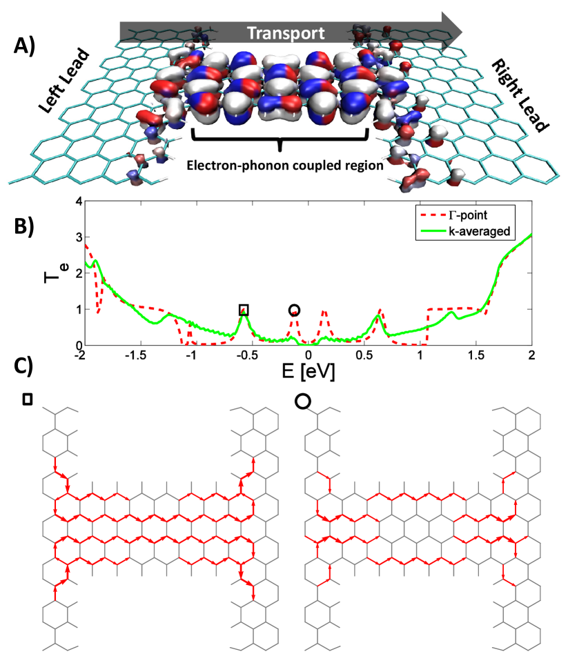
In this Letter, we calculate the current-induced phonon excitation in a small hydrogen-passivated GNC (Fig. 1) using parameters obtained from density functional theory (DFT). We find a highly non-linear heating of the GNC which we trace back to the deterministic current-induced forces, as opposed to the Joule-heating by random forces. In particular, the nonequilibrium electronic friction force turns into an amplification for certain phonon modes in the GNC. These will dominate the dynamics beyond a certain voltage threshold leading to a breakdown of the harmonic approximationbode_scattering_2011; lu_laserlike_2011. Negative friction was theoretically predicted in the tunneling transport through asymmetric moleculesryndyk_nonequilibrium_2006; lu_laserlike_2011 driven by population inversion between two molecular states. In contrast, we show here how the GNC can display negative friction due to a build-in asymmetry of phonon emission/absorption.
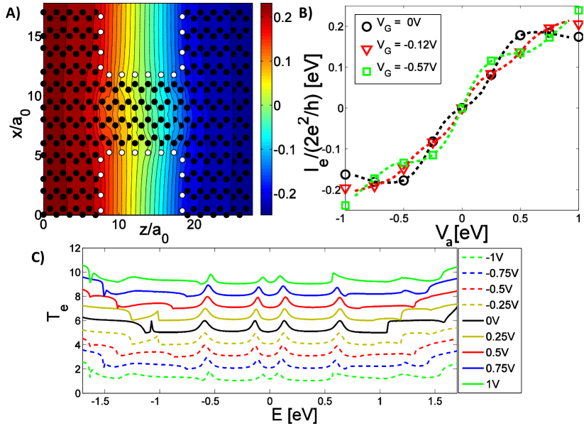
In Fig. 1B we see how the electron transmission of the GNC for energies around the charge neutral Fermi energy () is dominated by two resonance peaks originating from states presenting localized current along the edges(1st peak) and through the center(2nd peak) of the GNC, respectively. Resonances occur due to the diffraction barrier at abrupt interfaces in graphenedarancet_coherent_2009. By employing a gate voltage() we may tune close to a highly conducting peak and consider the phonon excitation close to the resonance. We will focus on the constriction gated to the 2nd peak, which is mostly unaffected by the boundary conditions in the electrodes(k-point sampling)brandbyge_density-functional_2002, and exhibits little dependence on the applied bias (), see Fig. 2.
To address the phonon excitation in the presence of current we employ the semi-classical generalized Langevin equation (SCLE)lu_blowing_2010; bode_scattering_2011; lu_current-induced_2012; lu_current-induced_2011. The SCLE describe the Joule heating, current-induced forces, and coupling to electrode phonons in the same formalism. For the mass-scaled ion displacements () the SCLE reads,
| (1) |
Here is the force constant matrix. The coupling to the electron and phonon baths are described by the retarded phonon self-energies , and the random noise force, , accounts for the Joule heatinglu_blowing_2010. We consider the retarded self-energy due to the interaction between the phonons and the electronic current,
| (2) | |||||
which is given by the interaction-weighted electron-hole pair density of states, , and its Hilbert transform()Hilbert_def. The four terms in this expression yields the electronic friction, non-conservative wind, renormalization and Berry forces in nonequilibrium conditions, respectivelylu_current-induced_2012. Especially for the nonequilibrium electron system, , with contributions from left/right leads (),
| (3) | |||||
Here is the coupling to phonon mode , the electronic spectral density for states originating from lead with chemical potential , and the Fermi distribution. The spectral density for the noise, , including the Joule heating, is given by,
| (4) | |||
Importantly, we include the full electronic and phononic structure of the graphene electrodes, and go beyond the constant/wide-band approximation(WBA) for the electronic structure. This is essential for our results of the phonon excitation when the graphene system is gated close to electronic resonance. We determine all parameters entering the SCLE above in the presence of current using first principles DFT and nonequilibrium Green’s functions (DFT-NEGF)soler_siesta_2002; brandbyge_density-functional_2002; frederiksen_inelastic_2007; FN_settings. We restrict the el-ph interaction to the GNC-region where the current-density is high, and evaluate the electronic spectrum at finite bias, but neglect the small voltage-dependence of and .
We note that the GNC device-region in the present calculation encompass a basis of 1336 orbitals for the electronic subsystem (matrix size in Eq. 3). Thus in order to efficiently compute in Eq. 3 beyond WBA we first limited the basis. We employed an expansion of the retarded Green’s function and in the eigenspace of , being the electronic Hamiltonian and the lead self-energies, which vary slowly with energyegger_vibration-induced_2008. We have found it sufficient to limit this basis to 200 states within the interval [-7,6]eV around . Secondly, we computed by parallel execution over the and parameters.
From Eq. 1 we can obtain the nonequilibrium retarded phonon Green’s function,
| (5) |
and the excitation in terms of the average kinetic energy of the phonons,
| (6) |
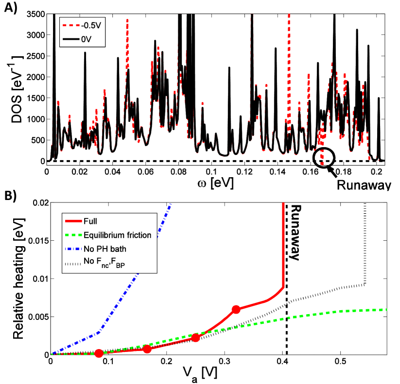
The phonon density of states (DOS) is given by . The DOS is affected both by the coupling to electrons, in particular giving rise to nonequilibrium forces, as well as coupling to the electrode phonons. In Fig. 3A we show the phonon DOS at applied bias of and V. Most importantly, the DOS becomes negative at a particular phonon frequency (meV), corresponding to a negatively damped mode, denoted ”runaway”. From Eq. 6 the runaway gives rise to a divergence in the current-induced change of (heating) of the GNC at V, see Fig. 3B. This signifies an instability in the harmonic approximation, where the high excitation is likely lead to dramatic effects such as contact disruptiondundas_current-driven_2009.
The instability can be traced back to the bias dependent electronic friction, and disappears when this is kept at its zero-bias value. We further note that for above V the deterministic current-induced forces lead to a qualitatively different heating compared to that of Joule heating only. Figure 3B furthermore show how the damping due to electrode phonons is crucial: The heating increase by an order of magnitude if the electrode-phonon bath is neglected. Moreover, if we neglect the damping due to the phonon-bath we observe runaway starting already at V, increasing to more than 15 runaway modes at V, both due to the effects of negative friction and nonconservative forcesdundas_current-driven_2009. The nonconservative wind and Berry-phase forces are found to be on the same order of magnitude for the runaway mode. Even though they do not themselves lead to the first runaway condition they lower the runaway threshold.
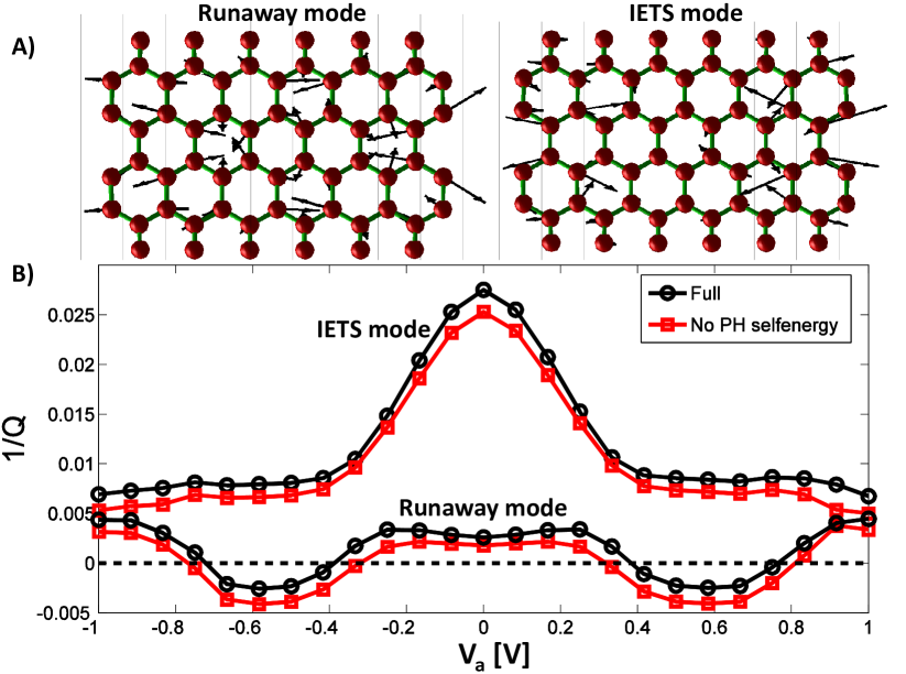
We will now in detail analyze the origin of the runaway. We focus on the modes contributing to the phonon DOS peak around the runaway, meV. They can be found as the eigenvectors of . The two main modes are displayed in Fig. 4. The ”IETS-mode” exhibits the largest inelastic tunnel spectroscopy signal(IETS) in the electronic current and largest noise , while the ”runaway mode” is the first mode that turns unstable with increasing . In Fig. 4 we show the inverse quality factor, (energy loss/period), for the two modes as a function of . The -factor is relatively big, especially for the runaway mode, due to low phonon DOS around . The runaway corresponds to amplification, , while remains for the IETS mode despite a strong decrease with bias.
It is instructive to view the runaway in terms of phonon absorption/emission processes in a simple master equation for the phonon number, ,
| (7) |
where () are the rates for absorption(emission). From Fermi’s golden rule we find the emission,
and is obtained by a replacement . Only a single scattering state, , contributes to and . Expressed in the single flux-normalized eigenchannel, and assuming , we have,
| (8) |
Here we did not include the intra-electrode terms() in since these vary only slightly with for the runaway mode. The phonon absorption rate decrease while the emission rate increase as the bias exceeds the mode frequency, see Fig. 5A.
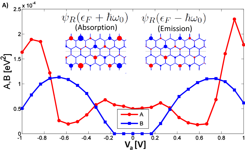
The electronic friction is given by the difference . This difference manifests itself in how the -factor vary with bias for the runaway mode. Importantly, we note that the symmetry of the scattering state is almost unchanged from going up in energy (absorption), see shown in the inset in Fig. 5A. On the other hand the symmetry of differs significantly from this. Thus we can expect in general that a given phonon will yield very different emission and absorption matrix elements due to the symmetry. In particular, the el-ph matrix element of the runaway mode yield very low absorption and high emission due to the selective symmetry of this phonon mode. The large phonon frequencies and linear DOS of graphene strengthens this symmetry breaking. The negative electronic friction is found for several modes and seems to be a generic phenomena in graphene nanostructures.
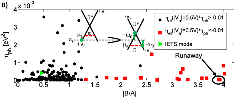
In Fig. 5B we illustrate how each mode shows up in a parameter space of the phonon friction and . The dominating runaway mode shows up at high and low phonon friction. The other modes with a non vanishing negative electron friction are also displayed. All these modes have , coefficients with same generic behavior as the first runaway mode (Fig. 5A). In the general case where one has a resonance between graphene leads, insert of Fig. 5B, the wave incoming at resonance will absorb to an eigenstate close to the Dirac crossing. Hence it will have low DOS and a dissimilar phase. On the contrary emission leads to an eigenstate with larger DOS and similar phase. This holds true for states dominated by the inter-lead contributions. Compared to the ”runaway” mode the ”IETS” mode has low emission-absorption ratio due to high intra-electrode terms, and a higher phonon damping.
We conclude that negative friction can appear for certain phonons in realistic systems such as graphene nanoconstrictions in the presence of electrical current. The negative friction effect is here rooted in the high phonon energies which lead to markedly different symmetry of the electronic states involved in emission and absorption and thus different matrix elements and rates. Two-dimensional systems like graphene, where a gate can be applied, makes an exciting test-bed for probing effects of electronic current on the atomic scale.
Acknowledgments – We thank the Danish Center for Scientific Computing (DCSC) for providing computer resources. The Center for Nanostructured Graphene(CNG) is sponsored by the Danish National Research Foundation.