Sub-Stream Fairness and Numerical Correctness in MIMO Interference Channels
Abstract
Signal-to-interference plus noise ratio (SINR) and rate fairness in a system are substantial quality-of-service (QoS) metrics. The acclaimed SINR maximization (max-SINR) algorithm does not achieve fairness between user’s streams, i.e., sub-stream fairness is not achieved. To this end, we propose a distributed power control algorithm to render sub-stream fairness in the system. Sub-stream fairness is a less restrictive design metric than stream fairness (i.e., fairness between all streams) thus sum-rate degradation is milder. Algorithmic parameters can significantly differentiate the results of numerical algorithms. A complete picture for comparison of algorithms can only be depicted by varying these parameters. For example, a predetermined iteration number or a negligible increment in the sum-rate can be the stopping criteria of an algorithm. While the distributed interference alignment (DIA) can reasonably achieve sub-stream fairness for the later, the imbalance between sub-streams increases as the preset iteration number decreases. Thus comparison of max-SINR and DIA with a low preset iteration number can only depict a part of the picture. We analyze such important parameters and their effects on SINR and rate metrics to exhibit numerical correctness in executing the benchmarks. Finally, we propose group filtering schemes that jointly design the streams of a user in contrast to max-SINR scheme that designs each stream of a user separately.
Index Terms:
MIMO, interference channel, fairness, SINR, rate, interference alignment.I Introduction
The prominent paper [1] proposed a new technique that was coined interference alignment (IA), and IA was shown to achieve the upper bound of non-interfering signaling dimensions in an interference channel (IC). Later, the limits of IA in multiple-input multiple-output (MIMO) ICs were mainly identified in [2] and in consecutive papers [3, 4]. The numerical results of IA first appeared in [5], where authors proposed a distributed IA (DIA) algorithm. In [5], IC extension of the conventional signal-to-interference plus noise ratio maximization (max-SINR) for point-to-point channels was also proposed. Max-SINR could achieve higher sum-rate than DIA in the low to mid signal-to-noise ratio (SNR) regime. Subsequently many papers proposed other techniques that offered improved sum-rates than DIA and max-SINR could achieve. Please refer to [6] and the references therein. However, all these techniques overlooked an important quality-of-service (QoS) metric, sub-stream fairness, i.e., fairness between streams of a user.
Although the acclaimed max-SINR algorithm lacks art in its design approach, its sum-rate results in MIMO ICs is surprisingly satisfactory. It is the curiosity to design the streams of a user (sub-streams) jointly, thus sub-streams are not considered as interference on one another. In fact, numerical results of an algorithm can significantly deviate by varying its algorithmic parameters, and in addition, different algorithms have different responses to algorithmic parameters. Therefore carefully scanning these parameters is important to benchmark entirely. For example, the sum-rate gap between max-SINR and DIA in low to mid SNR regime can be emphasized or both can be asserted as not achieving sub-stream fairness when screening of parameters shortfall.
In this paper, we propose a distributed power control algorithm (DPCA) in an ad-hoc manner to recognize sub-stream fairness in the system. Particularly, we initially obtain the beamforming vectors via conventional schemes including max-SINR and DIA with even power distributions, and then apply our DPCA to ensure sub-stream fairness with a slightly increased algorithmic load. In the paper, we also propose two new algorithms that jointly design sub-streams. Finally, we briefly discuss important algorithmic parameters and their influences on benchmarks.
II System Model
We consider a -user interference channel, where there are transmitters and receivers with and antennas at node , respectively. A transmitter has streams to be delivered to its corresponding receiver. This system can be modeled as where are the received signal vector and the zero mean unit variance circularly symmetric additive white Gaussian noise vector (AWGN) at the receiver, respectively. is the signal vector transmitted from the transmitter and is the matrix of channel coefficients between the transmitter and the receiver. is the power of the transmitter. The transmitted signal from the user is , where is the precoding (beamforming) filter and is vector denoting the independently encoded streams transmitted from the user. The receiver matrix is denoted by .
III Overview of Conventional and New Algorithms
This section begins with an overview of three conventional algorithms, DIA, max-SINR, and minimization of sum of mean square errors (min-sum-MSE). Later in the section, we introduce two schemes that jointly design the streams of a user as opposed to max-SINR scheme that considers streams of a user as interfering and designs the beamforming vectors of a user independently. In other words, our proposed schemes are based on group filtering, and allow collaboration between beamforming vectors of a user as opposed to max-SINR algorithm that undergoes intra-user interference disadvantage. In the next section, we also show that reckoning the streams of a user as whether interfering or not causes insignificant difference in sum-rate performance of max-SINR.
III-A DIA
Interference alignment (IA) packs multi-user interference in a space separate from the desired signal space [1]. This scheme achieves optimal degrees of freedom (DoF) in MIMO ICs. IA is feasible provided the following conditions satisfied
| (1a) | ||||
| (1b) | ||||
where indicates the zero matrix. The second condition (1b) is automatically satisfied for MIMO channels without specific structures. In [5], a DIA algorithm was proposed based on network duality. Particularly, transmit and receive beamforming vectors are updated iteratively to minimize (align) the interference. The interference leakage at receiver can be defined as , where denotes the trace of matrix and is the interference covariance matrix of user . To minimize the interference, eigenvectors corresponding to the smallest eigenvalues of the interference covariance matrix are assigned to IA receive beamforming vectors , where is the receive beamforming vector (i.e, column of the receive filter) of user , and denotes the eigenvector () corresponding to the eigenvalue () of matrix . At each iteration of the algorithm, assume eigenvectors are sorted in increasing order of corresponding eigenvalues, , and assigned to beamforming vectors in the same order, i.e., . Before the algorithm converges, the interference seen by the beamforming vector can be lower than the beamforming vector, whereupon SINRs and rates of succeeding sub-streams can be lower than the formers.
III-B Max-SINR
As known IA is DoF optimal, in other words it achieves the maximum multiplexing gain at high SNR
| (2) |
where and are the interference plus noise and identity matrices, respectively, and are the covariance matrix and rate of user , respectively, finally is the DoF (multiplexing gain) achieved by user , hence DoF is an approximation to rate. In fact sum-rate, , is more valuable than the DoF metric in real life. IA aims to minimize the interference, in other words the desired signal power is not considered. Ergo these reasons, foci of IA are minimizing the interference and achieving the optimal DoF, its sum-rate can be improved vastly in the low to mid SNR regime. As yet the optimal max-SINR scheme is not known for ICs, IC extension of the optimal max-SINR filter for a single stream and point-to-point system shows compelling sum-rate performances in ICs. The results are surprising since max-SINR can still perform higher than DIA for high number of users and streams per user [7] although it has the intra-user interference disadvantage. Basically, max-SINR maximizes the SINR of each stream separately
| (3) |
where , and is the covariance matrix of stream of the user. Note that contains the intra-user interference. The filter (3) is optimum if only it were to maximize the SINR of the stream of the user
| (4) |
Here SF stands for separate filtering since max-SINR designs each stream of a user independently from one another. Max-SINR is apparently sub-optimal even for a point-to-point system with multiple streams since the streams are competing with each other. A better approach is to design beamforming vectors by allowing cooperation between them [8]. As observed in DIA, stream SINRs and rates can be unbalanced due to the inherent competition between the streams.
III-C Min-Sum-MSE
In [6], an algorithm that minimized the sum of mean-square errors (min-sum-MSE) of all users was proposed. Although the objective function of min-sum-MSE does not aim SINR and rate fairness between streams, the simulation results show a rather well achieved fairness in terms of these QoS metrics.
III-D GEVD
As the name indicates, generalized eigenvalue decomposition (GEVD) is the generalized version of eigenvalue decomposition
| (5) |
Since the maximum value of (4) is equal to the largest generalized eigenvalue () of (5), generalized eigenvector corresponding to is assigned to beamforming vector . GEVD solution (5) and max-SINR filter (3) are equivalent for single stream per user systems. For multi-stream per user systems, GEVD solution (5) can be extended straightforwardly
| (6) |
where are the generalized eigenvalues. Here note that does not contain intra-user interference. GEVD in matrix form (6) is solved by assigning generalized eigenvectors corresponding to largest generalized eigenvalues to beamforming matrix . Comparing (5) and (6), we see that streams of a user are competing in max-SINR solution whereas they are collaborating in GEVD solution. Hence GEVD falls into group filtering schemes whereas max-SINR fits under separate filtering. GEVD is another bandwidth inefficient scheme since it orthogonalizes the desired () and interference plus noise () signal spaces. We remind that the sum-rate of max-SINR similarly diminishes as SNR or the number of streams per user increases since it acknowledges intra-user interference.
obtained from the GEVD solution (6) is the optimal filter for the problem which is an approximation to the trace quotient maximization problem
| (7) |
The stream SINR of group filtering (GF) schemes can be defined as Hence average SINR per user is given as a trace quotient
| (8a) | ||||
| provided beamforming vectors are adjusted to satisfy the condition | ||||
| (8b) | ||||
where is a constant. The motivation for maximizing average SINR, problem (7) given the condition (8b) holds, is given later in this section. Next we present a semidefinite programming (SDP) scheme that optimally solves the average SINR maximization problem.
III-E SDP
Trace quotient maximization arises in various fields of engineering, however we find only the SDP approach in [9] appropriate to use in the field of communications engineering. Next some comparisons are given. First, SDP, GEVD and max-SINR come in order from the highest to the lowest average SINR achieving schemes. Second, while they all achieve proximate SINR per user results, for single stream per user systems, they achieve the same results. Finally, it is worth mentioning the convergence rate of SDP is much slower than min-sum-MSE, and the convergence rate of min-sum-MSE is much slower than the other algorithms in the paper (DIA, max-SINR and GEVD). Further details and numerical results of SDP will be contained in journal version.
III-F On Group Filtering
As aforementioned, conventional max-SINR algorithm is sub-optimal since the SINR of each stream is maximized, thus the streams of a user are considered as interference on one another. As highlighted, GEVD and SDP jointly optimize the transmit beamforming vectors, thus the streams of a user are collaborating as opposed to the max-SINR algorithm. These two group filtering based schemes can be used for maximization of average SINR, a useful QoS metric in communications. This metric approximates the achievable rate at low SNR, and average SINR maximization simplifies the power allocation problem [8], where a centralized power allocation algorithm was proposed for MIMO downlink channels. In the next section, we also introduce a DPCA based on average SINR maximization to achieve user fairness in MIMO ICs.
Shannon’s formulation (2) assumes a nonlinear decoder, in our context e.g., maximum likelihood (ML) decoder [10]. As well known, a nonlinear decoder jointly decodes the streams of a user, thus in Shannon’s formulation, the streams of a user are considered as non-interfering. Therefore, the motivation of max-SINR to consider intra-user interference is not clear as shown next. Consider a modified max-SINR filter that does not reckon intra-user interference, i.e., the interference covariance matrix is used instead of in (3). Our numerical results show that by using Shannon’s formula (2), there is nearly no difference between the modified and conventional max-SINR algorithms. In other words, Shannon’s formula absorbs the disparity between reckoning and not reckoning the intra-user interference. Due to the same reason, separate and group filtering based schemes have similar rate results when Shannon’s formula is used.
IV Sub-Stream Fairness
In this section, we initially show the effects of stopping criteria on sub-stream fairness. Max-SINR algorithm dispenses unequal stream SINRs and rates within each user, on the other hand DIA can provide sub-stream fairness depending on the stopping criteria while min-sum-MSE is more robust to the stopping criteria. Before we propose a DPCA for balancing sub-stream SINRs in MIMO ICs, we list some important algorithmic details next. As already stated, these details can significantly change the perceptions on compared schemes. Further discussions on algorithmic parameters will be covered in the journal version.
IV-A Algorithmic Parameters
For all simulations in the paper, we fix the number of initializations of random transmit beamforming vectors to one. The numerical results show that if more initializations are allowed, the sum-rate gap in the low to mid SNR regime between DIA and max-SINR is reduced. The abbreviation Iter in the plots stands for the number of iterations between uplink and downlink, basically a downlink and then an uplink iteration count for two. Iter= indicates the number of iterations is not predetermined, and the algorithm stops when the increment in the sum-rate is negligible where stands for the iteration number, and is in our simulations. MC denotes the number of Monte Carlo simulations, and in the paper we present several results for the system . Finally, it is empirically observed for max-SINR that sum of stream rates
| (9) |
approaches to Shannon’s sum-rate as the algorithm iterates [11]. In (9) we do not indicate SINRs as SF or GF since the equations are valid for both. While for GEVD the same approximation holds, for DIA and min-sum-MSE this approximation is looser as observed from numerical results. Nevertheless, we evaluate the stream rates () as in (9), i.e., . Further discussion on this approximation will be included in the journal version.
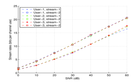
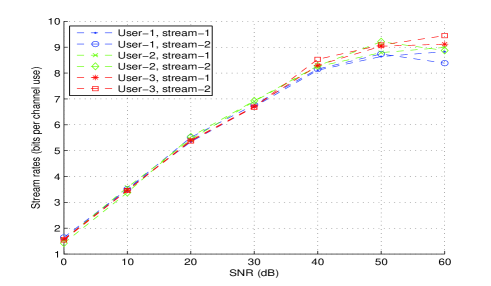
In Fig. 1, stream rates of max-SINR and min-sum-MSE are presented. While max-SINR appoints unequal rates to streams of a user, min-sum-MSE allocates quite fair rates between all streams in the system. A similar observation can be revealed for SINR results. From 0 to 60 dB, the sum-SINR ratios of the 2nd to the 1st streams, are 5 and 1 in average for max-SINR and min-sum-MSE, respectively. As the SNR increases to 60 dB, the imbalance of max-SINR reaches to 7 whereas it stays around 1 for min-sum-MSE. For all mentioned algorithms, the balance improves or worsens in direct proportion to the iteration number. As seen in Fig. 1(a), max-SINR cannot achieve fairness even for Iter=, whereas min-sum-MSE still preserves fairness at a much better level even for a low number of iteration as seen in Fig. 1(b). The simulation results of DIA show that it achieves reasonable sub-stream fairness for Iter= while for fixed number of iterations, streams of a user are imbalanced similar to max-SINR. The results of DIA are not plotted due to space limitations. As known, bit error rate (BER) is influenced by the worst stream SINRs in the system. Thus, in general, min-sum-MSE can provide lower BER than max-SINR due to its stream fairness, and max-SINR can achieve lower BER than DIA since it additionally aims to maximize desired signal power. In [6], BER performances are compared for a small iteration number, Iter=16. Since the imbalance between streams in max-SINR and DIA soar marginally more than min-sum-MSE as the iteration number decreases, BER gaps between these schemes are significant at Iter=16. These findings again indicate the influence of iteration number, as other algorithmic details do, on perceiving the complete picture.
IV-B Power Control for Fairness
SINR and rate fairness between users and streams can be achieved via joint power control and beamforming design or only via power control design. In this section, we initially propose a DPCA based on average SINR metric, i.e., trace quotient maximization with the constraint (8b). As alleged before, this is a handy metric that facilitates power control problems. Pioneering works in power control mainly fall into two groups, centralized [12] and decentralized [13] algorithms. A simple DPCA proposed in [14] was extended to a more general framework in [13]. In [13], the author defined interference function as standard if it satisfied monotonicity and scalability properties, and thereon constituted a standard power control algorithm (SPCA). Thanks to average SINR metric, SPCA becomes conveniently available. Later in this section, we present another DPCA to achieve SINR fairness between sub-streams.
IV-B1 User Fairness
Recently, a SPCA for DIA was proposed in [15]. The author erroneously defined SINR of a user as trace quotient formulation (8a). Except this flaw in [15], the author successfully showed that the interference function satisfied monotonicity and scalability properties. Here we only re-state the power constraint per user in its correct form since the rest of the proof is similar to [15]. User achieves Shannon’s information rate under the condition
| (10) |
given (8b) holds. By using (8a) and (10), the power constraint is given as where is the interference function of user and is the power vector of the system. We note that the same author proposed a corrected version of the algorithm by introducing power control per stream in [16] that satisfied preset rate targets per user.
IV-B2 Sub-Stream Fairness
Fairness in the system can be achieved by two complementary approaches, maximization of minimum SINR subject to power constraint or minimization of power subject to SINR constraint, and at three different levels, fairness between streams, users, or sub-streams. Both problems achieve optimal solutions when, depending on the intended level, streams’, users’, or sub-streams’ SINRs are attained with equality [17]. From more to less restrictive, stream, user and sub-stream fairness come in order. Consequently, sub-stream fairness causes the least degradation in sum-rate, followed by user and stream fairness. To this end, we propose an ad-hoc DPCA to retain fairness at the sub-stream level by using the later approach, minimization of power subject to SINR constraint. Basically, transmit and receive beamforming vectors are initially obtained via a scheme presented, but not limited to, in Section III. Then, in an ad-hoc manner, we apply the power control presented in Algorithm 1. The outer while loop searches for a feasible SINR target for each user. Since there is a maximum power constraint, the optimal power values may not be feasible if SINRs are not well balanced before power control applied. The superscripts denote iteration index in Algorithm 1, is the power vector of user , and is the power for the stream of the user at iteration , . and are interference plus noise and interference covariance matrices, respectively, is akin to a covariance matrix, is a diagonal matrix of sub-stream powers, is all ones vector, and are the vectors of interference functions and sub-stream SINRs, respectively.
V Numerical Results
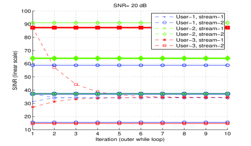
The proposed ad-hoc DPCA typically converges in a few outer while loop iterations, one such example for a channel realization at 20 dB is given in Fig. 2. Bold line in Fig. 2 indicates the average SINR and the other two horizontal lines are the maximum and minimum SINR values of the user’s streams before the power control algorithm is applied. In Fig. 2, the marks for horizontal lines are chosen the same with each corresponding user’s mark of the second stream. Note that the minimum SINR value of user 2 is close to the average SINR value of user 1, and the maximum SINR value of user 3 that is around 160 is not plotted. The stream SINRs of user 2 achieve close to the average SINR value of user 2 from the first iteration, thus the plots of these stream SINRs cannot be distinguished in the figure. As expected, the algorithm maximizes the worst SINR of the sub-streams as seen in Fig. 2, thus sub-stream fairness is achieved. Convergence of the algorithm is guaranteed since a feasible point is searched in the outer while loop of the algorithm. While for user 1 and 2, it takes only 2 iterations and 1 iteration respectively, for user 3, it takes 23 iterations for sub-stream SINRs to converge in fidelity of . In Fig. 2, only the first 10 iterations are plotted due to space constraints. Note that the algorithm ends when the total sum of differences between sub-stream SINRs is negligible. While this approach simplifies coding structure of Algorithm 1, it causes redundant iterations for user 1 and 2.
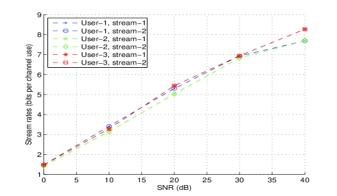
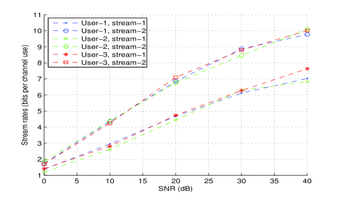
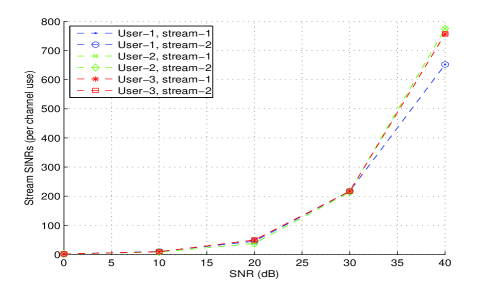
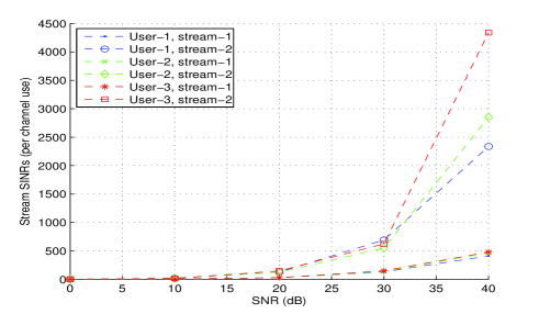
In Fig. 3 and 4, max-SINR without and with Algorithm 1 are compared for MC=20 and Iter=50. User rates and sum-rates can be obtained from the stream rates, thus omitted. For the same system in Fig. 3 and 4, but with Iter=, Algorithm 1 increased the simulation time by only 20 (the run-time increased from 40 sec to 48 sec). Note that the SINR and rate results can be significantly improved by designing beamforming and power vectors jointly.
VI Conclusion
Sub-stream fairness is an important QoS metric, and in addition it significantly influences the system’s BER performance. While conventional max-SINR scheme cannot achieve SINR fairness between sub-streams, DIA can achieve at a reasonable level depending on the stopping criteria of the algorithm. To address this problem, we proposed an ad-hoc DPCA that retained sub-stream fairness in the system with a slightly increased algorithmic load. We also proposed two new algorithms that designed sub-streams jointly instead of independently as max-SINR did. Finally, we showed that numerical results and our perceptions on benchmarks of schemes can be drastically shifted by varying algorithmic parameters. In addition to the future research directions already pointed in the paper, BER analysis is another important research direction.
VII Acknowledgement
We thank anonymous reviewers for helpful comments and thank the reviewer for bringing [16] to our attention.
References
- [1] V. R. Cadambe and S. A. Jafar, “Interference alignment and degrees of freedom of the K-user interference channel,” IEEE Trans. Inf. Theory, vol. 54, no. 8, pp. 3425–3441, Aug. 2008.
- [2] C. M. Yetis, T. Gou, S. A. Jafar, and A. H. Kayran, “On feasibility of interference alignment in MIMO interference networks,” IEEE Trans. Signal Process., pp. 4771 – 4782, Sep. 2010.
- [3] M. Razaviyayn, G. Lyubeznik, and Z. Q. Luo, “On the degrees of freedom achievable through interference alignment in a MIMO interference channel,” IEEE Trans. Signal Process., vol. 60, no. 2, pp. 812–821, Feb. 2012.
- [4] G. Bresler, D. Cartwright, and D. Tse, “Settling the feasibility of interference alignment for the MIMO interference channel: the symmetric square case,” 2011, ArXiv pre-print cs.IT/1104.0888v1. http://arxiv.org/abs/1104.0888.
- [5] K. S. Gomadam, V. R. Cadambe, and S. A. Jafar, “A distributed numerical approach to interference alignment and applications to wireless interference networks,” IEEE Trans. Inf. Theory, vol. 57, no. 6, pp. 3309–3322, Jun 2011.
- [6] H. Shen, B. Li, M. Tao, and X. Wang, “MSE-Based transceiver designs for the MIMO interference channel,” IEEE Trans. Wireless Commun., vol. 9, no. 11, pp. 3480–3489, Nov. 2010.
- [7] D. S. Papailiopoulos and A. G. Dimakis, “Interference alignment as a rank constrained rank minimization,” IEEE Trans. Signal Process., vol. 60, no. 8, pp. 4278 – 4288, Aug. 2012.
- [8] Y. H. Yang, S. C. Lin, and H. J. Su, “Multiuser MIMO downlink beamforming design based on group maximum SINR filtering,” IEEE Trans. Signal Process., vol. 59, no. 4, pp. 1746 – 1758, Apr. 2011.
- [9] C. Shen, H. Li, and M. J. Brooks, “Supervised dimensionality reduction via sequential semidefinite programming,” Elsevier, pp. 1 – 24, 2007.
- [10] S. W. Peters and R. W. Heath Jr., “Cooperative algorithms for MIMO interference channels,” IEEE Trans. Veh. Technol., vol. 60, no. 1, pp. 206 – 218, Jan. 2011.
- [11] C. Wilson and V. V. Veeravalli, “A convergent version of max SINR for the MIMO interference channel,” Int. Symp. on Inf. Theory, pp. 2208–2212, July 31 - Aug. 5 2011.
- [12] M. Schubert and H. Boche, “Solution of the multiuser downlink beamforming problem with individual SINR constraints,” IEEE Trans. Veh. Technol., vol. 53, no. 1, pp. 18–28, Sep. 2004.
- [13] R. D. Yates, “A framework for uplink power cellular radio systems,” IEEE J. Sel. Areas Commun., vol. 13, no. 17, pp. 1341–1347, Sep. 1995.
- [14] G. J. Foschini and Z. Miljanic, “A simple distributed autonomous power control algorithm and its convergence,” IEEE Trans. Veh. Technol., vol. 42, no. 4, pp. 641–646, Jun. 1993.
- [15] H. Farhadi, “Interference alignment and power control for wireless interference networks,” Ph.D. dissertation, Royal Institute of Technology, 2012.
- [16] W. C. Farhadi, F. and M. Skoglund, “Distributed interference alignment and power control for wireless MIMO interference networks,” IEEE Wireless Commun. Netw. Conf., Apr. 2013.
- [17] A. Wiesel, Y. C. Eldar, and S. Shamai (Shitz), “Linear precoding via conic optimization for fixed MIMO receivers,” IEEE Trans. Signal Process., vol. 54, no. 1, pp. 161–176, Jan. 2006.