Demonstration of active routing of entanglement in a multi-user network
Abstract
We implement an entanglement distribution network based on wavelength-multiplexing and optical switching for quantum communication applications. Using a high-brightness source based on spontaneous parametric down-conversion in periodically-poled lithium niobate waveguides, we generate polarisation entangled photon pairs with a broad spectrum covering the telecom wavelengths around 1550 nm. The photon pairs have entanglement fidelities up to , and are distributed via passive wavelength multiplexing in a static multi-user network. We furthermore demonstrate a possible network application in a scenario with a single centralised source dynamically allocating two-party entanglement to any pair of users by means of optical switches. The whole system, from the pump laser up to the receivers, is fibre and waveguide based, resulting in maximal stability, minimal losses and the advantage of readily integrable telecom components in the nm range.
pacs:
03.67.Dd, 03.67.Bg, 03.67.HkI Introduction
Quantum entanglement is an essential resource for many quantum information experiments, such as quantum teleportation, entanglement swapping and tests of Bell inequalities pan12 . It is also useful in quantum communication protocols such as Quantum Key Distribution (QKD) zbi02 . For QKD in particular, entanglement offers the additional advantage of device independent security sca07 . Entanglement-based QKD is now a well developed research area which has, in the last years, reached important practical milestones yam08 ; hub09 ; sch09 ; kur09 . Forefront developments in the field include also the realisation of more sophisticated multi-party QKD networks secoq ; tokyo , with trusted nodes connecting different independent QKD-links. So far however, only photonic qubits were distributed in these demonstrations, but no entanglement. The realisation of entanglement-distribution networks connecting multiple users sharing entanglement would permit a wide variety of quantum communication applications in addition to QKD such as secret key sharing ber99 and quantum complexity protocols dam01 .
Entangled photon sources (EPS) used in such networks should incorporate design features to integrate them easily into the existing telecommunication infrastructure. It is therefore advantageous to have compact, cheap and power-saving systems which are also compatible with fibre-based telecom components. For practical ground-based networks, the generation of entangled photons around 1550 nm is beneficial, since long distance transmission in fibre is optimal at that wavelength and there exist standardised grids in the form of Dense Wavelength Division Multiplexing (DWDM) and Coarse Wavelength Division Multiplexing (CWDM) itu .
A common technique to create and make practical use of entanglement is to produce polarization-entangled photons by spontaneous parametric down-conversion (SPDC) in second order () non-linear crystals kwiat1995nhi . The coupling of photons from the bulk crystal to optical fibres leads to a loss of robustness and reliability, both needed in practical applications. Non-linear crystals with inscribed waveguides and fibre pigtails overcome this problem and offer long term stability. In addition, waveguides also increase the efficiency of the down-conversion process by several orders of magnitude compared to bulk crystals gis01 . Entangled photon pairs have also been directly generated in dispersion shifted fibres via four-wave mixing techniques () LCLLVK06 . Such designs offer the advantage of an all-fibre based compact system with no coupling losses from crystal to fibre. The process however suffers from Raman scattering, leading to an increase in background photons. To limit the scattering, fibres have to be cooled with liquid nitrogen or the produced photon pair has to lie outside the scattering band ( nm) kan09 ; gov07 ; jen12 . Neither option is very practical for realistic telecom applications since cooling requires more maintenance and larger source designs, or the photons would lie outside the telecommunication band (1260-1675 nm), due to the large wavelength separation. Recent developments include the generation of entangled photon pairs in a twin-hole step-index fibre via nonlinearities li12 . Although this seems a promising way for the future, conversion efficiencies of -fibres are currently still much lower than in -crystals with waveguides which are the best candidates for practical realisations.
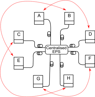
We report on the development of an EPS at 1550 nm based on SPDC in lithium-niobate (LiNbO3) waveguides. This approach combines robustness (waveguides and fibre pigtailing) with a clean process (low background) and results in a reliable high-brightness source tailored for quantum communication protocols. Moreover, we demonstrate bipartite entanglement distribution (depicted in Figure 1), from a centralised EPS in a network for eight users with passive wavelength multiplexing, the highest number reported so far kan09 ; lim08 , and easily extendable to many tens of users by using arrayed-waveguide gratings (AWGs). With a broadband EPS, all users receive a continuous stream of entangled photons at the same time, maximising the use of the fibre infrastructure. In addition we implement a software-defined network (SDN) for entanglement distribution, where we show active assignment of entanglement to any two users in a 4-user star-like network. We also achieve very high coincidence rates close to 550 counts/s for each entangled channel pair and obtain fidelities of more than 98% for the entangled states.
In Section II, we describe in detail the experimental setup, comprising the source, the implementation of active phase-stabilisation, the components designed for multi-user entanglement distribution, the polarisation analysis as well as the detection modules. We present, in Section III, the key performance parameters (coincidence rates and conversion efficiency), as well as the results of tomographic measurements on the entangled channels. With the introduction of optical switches we demonstrate in Section 4 a “any Alice to any Bob” 4-user SDN application for entanglement distribution, before concluding in Section V.
II Setup
II.1 Source of polarisation entangled photons
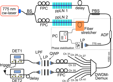
The source, depicted in Figure 2, is based on two 30 mm long, periodically poled LiNbO3 crystals (ppLN) arranged in a Mach-Zehnder interferometer to yield polarisation entanglement tsu03 . The crystals are type-0 quasi phase-matched (all interacting fields have the same polarisation) to support SPDC, converting pump photons at 775 nm to signal and idler photons at 1550 nm, with collinear emission at C. The phasematching condition at degeneracy is very broad even for our 30 mm long crystals, leading to a large spectral bandwidth of the entangled photon pairs of approximately 70 nm. However, the tight energy uncertainty of the narrowband pump photons at 775 nm restricts the photons of any pair to be symmetrically located in frequency around the central wavelength of 1550 nm. Each crystal contains an inscribed waveguide (proton exchange method) with a m2 mode field cross-section at 1550 nm (HC Photonics), guiding only vertical polarised light. Each waveguide is fibre-coupled to a m mode field diameter (MFD) fibre at the input (single mode for the pump), and a polarisation maintaining (PM) 1550 nm fibre with a MFD of m at the output (single mode for the generated photon pairs). Both crystals are pumped by a grating-stabilised narrowband continuous wave (cw) diode laser from Toptica Photonics (DL 100). The laser has a narrow linewidth of MHz, and can be tuned between nm and nm. A fibre port at the laser head couples around 10 mW of the laser light into a single mode fibre.
As shown in Figure 2, the pump field is split, at a ratio of , into the two spatial modes of the interferometer with a fibre-based beam splitter (BS) and is then directed to the single mode input fibres of the crystals. Since the quasi phase matching is dependent on the pump polarisation, fibre polarisation controllers (FPC) in each arm are used to adjust the polarisation of the incident pump field to generate pairs with vertical polarisation. The horizontal polarisation component of the pump does not contribute to the SPDC process and is also not guided by the waveguide. The PM fibres at the output face of each crystal are aligned with their slow axis parallel to the polarisation direction of the generated signal/idler pair. Once inside the PM fibre, the polarisation of the pair will remain parallel to the slow axis of the fibre. The two PM fibres are then combined using a fibre-based polarising beam splitter (PBS). This device fuses two input PM fibres into a standard single mode fibre, whereby one of the two PM fibres is turned by . Hence, the polarisation of the pairs from ppLN 2 is turned by with respect to the polarisation of the pair from ppLN 1. Since both crystals initially produced pairs with vertical polarisation , the entangled state is created, where is the phase accumulated in the interferometer, as discussed in Section 2.2. In our setup, the pump and down-converted photons are exclusively transmitted in guided modes (e.g. single-mode fibres and waveguides), making realignments obsolete.
To tune the wavelengths of signal and idler photons, the crystal temperature was controlled by electrical heaters. Degeneracy, where signal and idler photons have the same spectral properties, was achieved by setting the temperature of ppLN1 and ppLN2 to 66.9 ∘C and 57.5 ∘C respectively, indicating small differences during production.
II.2 Active phase-stabilisation
The state of the polarisation entanglement is dependent on the phase difference of both arms of the Mach-Zehnder interferometer. Since this phase is very sensitive to changes arising from temperature variations and mechanical vibrations, an active stabilisation of the phase inside the interferometer was implemented. A standard telecom add-drop filter (ADF) with a 13 nm wide passband at 1550 nm is used after the interferometric stage to split the laser light (775 nm) from the down-converted light ( nm). The pump light is directed to a phase analyser, consisting of a linear polariser (LP) and a photo-diode. Since the pump light passes the whole Mach-Zehnder interferometer, the change in the phase difference between both arms is transformed to intensity fluctuations after the polariser (set to in the laboratory frame). Phase changes of around per second were found, clearly indicating the need of an active stabilisation routine. The output signal of the photodiode was fed into a computer, which in turn produced voltages to drive a fibre stretcher in one arm of the interferometer. Stretching the fibre leads to a slight path length difference and hence a change in the relative phase of the interferometer. By adding a constant stretching via a software interface, the fibre stretcher is also used to set the phase of the entangled state on demand. For the rest of this work the phase was fixed to to obtain the desired Bell-state: .
II.3 Multi-user distribution
The broad bandwidth of photons generated by the source presented here can be used to distribute bipartite entangled states to many users (8 users in our case) at virtually the same time. A passive 8-channel demultiplexer (Demux) with channel spacings of 200 GHz matched to the DWDM grid, and channel widths () of 62 GHz (0.5 nm), was used to split the broad spectrum into 8 output fibres. By careful tuning the pump laser wavelength, the central frequency of the down-converted field fell exactly between the two central channels of the DWDM-Demux. This configuration resulted in four possible pairs of entangled channels at wavelengths of 1549.32/1550.92 nm, 1547.72/1552.52 nm, 1546.12/1554.13 nm and 1544.53/1555.75 nm, as shown in the first column of Table 1 and numbered in the standard ITU channel notation (ch. 27 to ch. 41). Any such set of two entangled channels can be directed via single-mode fibres to users wishing to share entanglement or, as in our setup, to a polarisation analysis and detection module. The narrow filtering of the DWDM-Demux also increased the temporal coherence of the single photons, such that dispersion effects in long distance fibre transmission are reduced. The value for polarisation mode dispersion, which leads to depolarisation of the photons, is ps for a 100 km fibre link hub07 , much less than the coherence time of ps given by the DWDM-Demux bandwidth. For a standard telecom fibre of 100 km length, the chromatic dispersion for such narrow filtering would equal to a temporal photon spread of ns, which is also acceptable. Using non-zero dispersion-shifted fibres would narrow the spread even further to below 0.5 ns, the exact value depending on the wavelength of the single photons due to the variation of chromatic dispersion (5.5-10 ps/nm/km) over the C-band (1530 nm to 1565 nm). Another advantage in using the DWDM grid is the possibility to run the quantum channel alongside other classical channels in the same fibre, as demonstrated in Lo10 and hence optimising fibre resources.
II.4 Polarisation analysis and detection
To quantify the degree of polarisation entanglement, a full state tomography was performed for each channel pair. For this measurement, the photons in each channel passed, in free space, a quarter wave plate (QWP) followed by a linear polariser (LP) and long-pass filters (LPF), before being coupled to single mode fibres again. The long-pass filters were used to remove any residual pump light at 775 nm. Fibre-based polarisation controllers (FPC) were introduced before the free space unit to compensate for the unitary rotation of the polarisation state induced by the birefringence of the optical fibre.
The photons of each entangled channel pair were detected by two single-photon InGaAs avalanche photo diodes (APD), Id-200 from idQuantique. Since our source was pumped by a cw-laser, no synchronisation signal, normally used to trigger the InGaAs APDs, was available. One detector (DET1), with detection efficiency of 10% (), was instead operated with internal triggering and, upon a detection event, triggered the second detector (DET2), with detection efficiency of 15% (). The internal triggering mode on DET1 was achieved by using the longest possible gate of 100 ns and an internal gate repetition rate () of either 100 kHz or 1 MHz. This implied a duty cycle () of only 1% or 10% respectively. The photons guided to the second detector were appropriately delayed using 15 m of fibres to coincide with the short 2 ns gate of DET2. The deadtimes of both detectors were set to 10 s. Free-running avalanche photo diodes war09 ; yan12 or high-efficiency superconduction-detectors nam08 ; nam13 are only now becoming commercially available and were not used in this experiment. Employing these advanced detection schemes would have increased our detected pair rates by 2-3 orders of magnitude compared to the values presented in the next chapter.
III Results
In contrast to typical SPDC setups where the pump laser is focused onto a small region of the non-liner crystal, the use of a waveguide with strong confinement over a long region of the crystal increases the interaction strength by several orders of magnitude. In the following section we give details of the generation process and detection rates, and characterise entanglement distribution using narrow and broad-band telecom multiplexers.
III.1 Coincidence rates and conversion efficiency
In order to accurately quantify the rates expected from the source, the total optical loss in the system was characterised using a tunable laser diode operated around 1550 nm. The coupling efficiency () of the waveguide to the fibres (input and output) was estimated to be , a figure provided by the manufacturer. The combined transmission of the fibre stretcher and fibre PBS was measured to be 90%. For channel 31, the ADF and DWDM-Demux had a combined transmission of 60%. Lower channel numbers showed higher transmission, whereas higher channel numbers had lower transmission. We believe this is due to the inherent geometry of the DWDM-Demux. Finally, the polarisation analysis units (QWP, LP and LPF) had a transmission of 75%. The total transmission through all optical parts from the waveguides to the inputs of the detectors was therefore .
To characterize the coincidence rates between signal and idler photons, a single crystal (ppLN 2) was used, and the pump power () was set to W. The detected single rate (signal photons) in channel 37 was 2600 counts per seconds (thereafter, c/s) using DET1 at duty cycle ( kHz). As expected from conservation of energy, idler photons were found in channel 31 and a coincidence rate () of 75 c/s was detected at DET2. The coincidence to single ratio was found to be , which compares favourably with the expected ratio of , given by the product of and . In order to improve , we increased the gate frequency of DET1 to 1MHz. This increased the single rate to 38000 c/s (of which 9000 c/s were dark counts) and to 450 c/s, yielding a ratio of only. We believe that the single rate is highly increased by afterpulsing effects. This can also be seen by the nearly 12-fold increase in the single rate, although only a 6-fold increase would be anticipated from the actual gate rate on DET1, which was down to kHz due to saturation. However the coincidence rate did increase by a factor of 6, which furthermore supports our hypothesis of afterpulsing. Waveguide ppLN 1 showed a similar behaviour, but with a lower single and coincidence rate. We attribute this to lossier fibre-waveguide couplings. To achieve equal coincidence rates between the two crystals, as required for Bell-state production, the effective pump power into ppLN 2 was reduced by slightly turning the input polarisation away from optimum. We also tested the quality of our fibre-pigtailed crystals by second-harmonic-generation (SHG). This reverse process to SPDC converts two pump photons at a wavelength around 1550 nm to a signal photon at 775 nm. We measured overall SHG-efficiencies of 186%/W and 218%/W for the crystals ppLN1 and ppLN2 respectively, again observing a slight difference in the conversion efficiency.
The fibre coupled brightness () of the source can be calculated by taking into account the detector efficiencies and bandwidth () of the photons. Using the data from the duty cycle run, this results in pairs/s/mW/GHz, which is several orders of magnitude higher than in comparable sources using nonlinear crystals without waveguides hen09 ; pru12 .
Since the crystals are fibre-coupled with known losses, an attempt was made to estimate the intrinsic conversion efficiency, i.e. the probability to create a photon pair given a single pump photon. This measurement was performed with an input power of 0.62 mW of 775 nm light, which yielded a SPDC output power of 1.7 nW at 1550 nm as measured with a standard power meter. The measured conversion efficiency is hence . Including the losses of the fibre coupling, , the intrinsic efficiency of the SPDC inside the waveguide is even larger and estimated to be . Hence, for every pump photons, one signal-idler pair is generated. This is in excellent agreement with a theoretical calculation of the conversion efficiency mun07 which yields for the specific ppLN waveguide used in the measurements.
III.2 Tomographic measurements on entangled channels
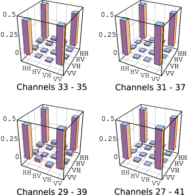
The polarisation state of each entangled channel pair was analysed using a state tomography measurement jam01 . Coincidences were measured in 16 polarisation settings (HH, HV, HP, HR, VH, VV, VP, VR, PH, PV, PP, PR, RH, RV, RP and RR), where H,V,P and R stand for horizontal, vertical, and right circular polarisation respectively. All coincidences, averaged over 20 seconds, were recorded with an input power of 18 W for each crystal and a duty cycle of 10% for DET1. The maximal coincidence rates measured were found to be around 450 c/s, as shown in Table 1. As previously mentioned, each channel of the DWDM-Demux has different insertion losses affecting the coincidence rates between channel pairs. Density matrices (), calculated from the raw coincidence rates for each channel pair, can be seen in Figure 3. Fidelities () and purities () for all four entangled channel pairs were also obtained, and are listed in Table 1. The fidelities have values around 93% indicating a high degree of entanglement of the raw data. This raw fidelity value yields a quantum bit error of %, low enough to establish a secret key between parties using the BBM92 QKD protocol bbm92 . The observed fidelity is also in very good agreement with a study predicting an entanglement visibility of 93% for entanglement distribution using a DWDM-Demux zaq13 . With substraction of the background of c/s, which consists primarily of accidental coincidences from higher order emissions and afterpulsing, fidelity and purity values of up to 99% are observed, also listed in Table 1. These values show that the source is producing entangled states at very high fidelity over all eight channels. Even when considering only one pair of DWDM-Demux channels, our source has the highest reported coincidence rate for a raw fidelity above 90% in similar waveguide sources tsu03 ; tsu05 ; tom06 ; lim08a ; ino11 .
| Entangled channels | Coincidence | Fidelity without | Purity without | ||
|---|---|---|---|---|---|
| central wavelengths [nm] | rate [c/s] | Fidelity | background | Purity | background |
| 33 - 35 | |||||
| 1550.92 - 1549.32 | 460 | 0.93 | 0.99 | 0.87 | 0.99 |
| 31 - 37 | |||||
| 1552.52 - 1547.72 | 450 | 0.92 | 0.98 | 0.89 | 0.98 |
| 29 - 39 | |||||
| 1554.13 - 1546.12 | 480 | 0.93 | 0.99 | 0.88 | 0.99 |
| 27 - 41 | |||||
| 1555.75 - 1544.53 | 430 | 0.93 | 0.98 | 0.88 | 0.99 |
III.3 Visibility measurements on entangled channels in a CWDM-grid
The spectrum of our source extends over 5 channels of the widely deployed CWDM telecom wavelength grid. Less stringent requirements on the wavelength accuracy leads to cheaper components and high availability paves the way for easy integration of QKD-systems in existing telecom networks. Therefore we replaced the ADF and DWDM-Demux with a 5 channel CWDM-Demux, and sliced the SPDC spectrum into 20 nm wide channels, with a 13 nm passband in each channel. The center channel at 1551 nm was used for the phase stabilisation. In order not to saturate our detectors we reduced the pump power to W per crystal and recorded a coincidence rate of around 200 c/s which is in agreement with the increased bandwidth of the channels. However visibility measurements for the entangled pairs in the channels with the central wavelength of 1531-1571 nm (1) and 1511-1591 nm (2) showed only values of and , respectively. With background subtraction the values increased somewhat to and , but were still below the near 100% mark achieved with the DWDM-Demux. We believe that the reduction of visibility is caused by the wavelength-dependent birefringence in the fibre. The large bandwidth of the CWDM-Demux causes different wavelenghts to experience different polarisation rotations in the optical fibre. Since our polarisation controller can only correct for a single specific rotation, a large part of the spectrum will deviate from the input polarisation state and hence cause a decrease in visibility. For this reason and because of the effects of chromatic dispersion, discussed above, it is important to optimise the source for a high spectral brightness () in order to limit the bandwidth of each channel as much as possible.
IV Multi-user entanglement distribution — “Any Alice to any Bob” network application
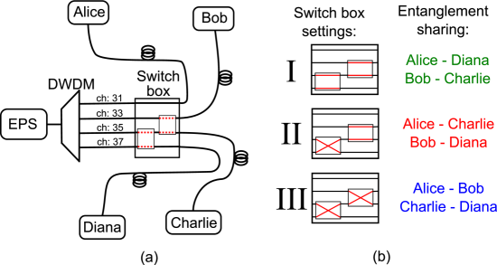
A single broadband photon source, as presented in the previous sections, can deliver entangled photon pairs to many users with the help of a wavelength multiplexer. However this type of entanglement distribution is static, as the entangled channels are always connected to the same users. A software-defined network, where users actively select their partners with whom they share pairs of entangled photons, can be achieved by adding an optical switch to the existing setup as shown in Figure 4(a).
We implemented such a SDN for 4 users, by incorporating two opto-mechanical switches from Cube Optics into four of the fibres leaving the DWDM-Demux. Both switches feature a port design (two inputs and two outputs) and are concatenated to allow for a switching of the entangled inputs to any output configuration. The distribution of bipartite entanglement between any two users out of four, was achieved by using three possible switch configurations, as schematically depicted in Figure 4(b).
Coincidence rates and polarization correlations for all possible switch settings were measured again. The rates together with the calculated state visibilities and purities for all user pairs are shown in Table 2. Coincidence rates were hardly affected by the addition of the two switches and the visibilities and purities show again a very high degree of entanglement between any pair of users.
The number of possible pairs supported by a single source of entangled pairs is only limited by the total emission bandwidth of photons. Using DWDM multiplexers or AWGs with the ITU-recommended 100 GHz spacing, the presented source with its 70 nm overall bandwidth could supply up to N=90 wavelength channels supporting 45 independent pairs of users at the same time. Shorter crystals would lead to even higher number of channels as the SPDC spectrum broadens. The decrease in brightness can easily be compensated by correspondingly higher pumping powers.
The switch box can be expanded to a NxM architecture with N wavelength channels serving M users by using well-established mathematical methods developed for telecom industry using a combination of 2x2-switches as the basic element. For standard telecommunication architectures, the requirement of non-blocking behaviour is usually important in order to guarantee any possible connectivity from one of the N inputs to any of the M output ports independent of other connections through the switching network. For the purpose of distribution of entangled photon pairs this very restrictive requirement is not necessary, because two users requesting entangled photon pairs to establish quantum correlation, for e.g. a secure QKD-link, are in generally not interested in: (a) which pair of wavelength (i.e. ITU-channels as indicated in Table 1) of the possible N/2 they will receive and (b) which photon of a pair. We therefore believe that entanglement distribution networks scale better in terms of loss than traditional telecommunication networks. In our example shown in Figure 4(b), we distribute N=4 different wavelengths of photons to M=4 users using only two 2x2 switches. A traditional non-blocking Clos-network would require 6 switches (three concatenated switches in parallel), and each photon would therefore experience three times the loss of a single switch. Moreover, each doubling of the number of input pairs would require the addition of two rows of switches, increasing the overall loss. A constant loss, independent of the number of users, could be achieved using a mirror array, typically based on Micro-Electro-Mechanical-System (MEMS) technology, which is commercially available for up to N=M=192 channels.
| Switch | Entanglement | Coincidence | Fidelity without | Purity without | ||
|---|---|---|---|---|---|---|
| setting | sharing | rate [c/s] | Fidelity | background | Purity | background |
| A-D | 440 | 0.93 | 0.98 | 0.89 | 0.98 | |
| I | B-C | 480 | 0.94 | 0.98 | 0.89 | 0.96 |
| A-C | 450 | 0.94 | 0.99 | 0.90 | 0.98 | |
| II | B-D | 480 | 0.95 | 0.98 | 0.93 | 0.99 |
| A-B | 480 | 0.92 | 0.98 | 0.86 | 0.96 | |
| III | C-D | 430 | 0.92 | 0.98 | 0.89 | 0.99 |
V Conclusion
We demonstrated entanglement distribution by combining an all fibre/waveguide source and standard telecommunication multiplexers connecting eight users in a static configuration. We also showed dynamically configurable links for entanglement distribution between four users switched by a scalable software-defined network. Using the wide bandwidth of degenerate SPDC, many more users could be fed from a single centralised source using DWDM components. Waveguide technology offers high SPDC efficiencies and enables the construction of more robust and integrated optical setups compared to conventional free-space systems with bulk crystals. Furthermore, the fibre pigtailing guarantees a stable coupling of the entangled photons into single mode fibres. As no alignment is necessary, the source produces a reliable and autonomous stream of entangled photons with a high coincidence rate. The narrow channel bandwidth (62 GHz) of the DWDM-Demux also reduces dispersion effects in optical fibres. Furthermore, the standardisation of the multiplexer allows the incorporation of a quantum channel in existing classical optical networks.
The observed entanglement fidelities after distribution were very high (), and reached up to with background substraction. Although we report the highest coincidence rates for a fibre pigtailed waveguide source, the rate was still limited by InGaAs APDs which were used in a gated mode with a maximal duty cycle of 10%. However advanced detector technology for the near-infrared is now commercially available and will remedy this problem in future.
VI Acknowledgements
We would like to thank Michael Hentschel and Sven Ramelow for technical assistance. This work was supported by the Austrian Science Foundation FWF (TRP-L135 and SFB-1520), the Natural Sciences and Engineering Research Council of Canada, Canada Foundation for Innovation, Canadian Institute for Advanced Research, Ontario Research Fund, and Industry Canada. We would also like to thank the Institute for Quantum Optics and Quantum Information, Vienna, for financial assistance in obtaining the waveguides. I.H. thanks the Institute for Quantum Computing, Waterloo, Canada, for hosting her during the writing-up phase of this article.
References
References
- (1) Pan J W, Chen Z B, Lu C Y, Weinfurter H, Zeilinger A and Żukowski M 2012 Rev. Mod. Phys. 84 777–838
- (2) Gisin N, Ribordy G, Tittel W and Zbinden H 2002 Rev. Mod. Phys. 74 145–195
- (3) Acín A, Brunner N, Gisin N, Massar S, Pironio S and Scarani V 2007 Phys. Rev. Lett. 98 230501
- (4) Honjo T, Nam S W, Takesue H, Zhang Q, Kamada H, Nishida Y, Tadanaga O, Asobe M, Baek B, Hadfield R H, Miki S, Fujiwara M, Sasaki M, Wang Z, Inoue K and Yamamoto Y 2008 Opt. Express 16 19118–19126
- (5) Treiber A, Poppe A, Hentschel M, Ferrini D, Loruenser T, Querasser E, Matyus T, Hübel H and Zeilinger A 2009 New J. Phys. 11 085002
- (6) Scheidl T, Ursin R, Fedrizzi A, Ramelow S, Ma X S, Herbst T, Prevedel R, Ratschbacher L, Kofler J, Jennewein T and Zeilinger A 2009 New J. Phys. 11 085002
- (7) Peloso M P, Gerhardt I, Ho C, Lamas-Linares A and Kurtsiefer C 2009 New J. Phys. 11 045007
- (8) Peev M, Pacher C, Alleaume R, Barreiro C, Bouda J, Boxleitner W, Debuisschert T, Diamanti E, Dianati M, Dynes J F, Fasel S, Fossier S, Fuerst M, Gautier J D, Gay O, Gisin N, Grangier P, Happe A, Hasani Y, Hentschel M, Hübel H, Humer G, Laenger T, Legre M, Lieger R, Lodewyck J, Loruenser T, Luetkenhaus N, Marhold A, Matyus T, Maurhart O, Monat L, Nauerth S, Page J B, Poppe A, Querasser E, Ribordy G, Robyr S, Salvail L, Sharpe A W, Shields A J, Stucki D, Suda M, Tamas C, Themel T, Thew R T, Thoma Y, Treiber A, Trinkler P, Tualle-Brouri R, Vannel F, Walenta N, Weier H, Weinfurter H, Wimberger I, Yuan Z L, Zbinden H and Zeilinger A 2009 New J. Phys. 11 075001
- (9) Sasaki M, Fujiwara M, Ishizuka H, Klaus W, Wakui K, Takeoka M, Miki S, Yamashita T, Wang Z, Tanaka A, Yoshino K, Nambu Y, Takahashi S, Tajima A, Tomita A, Domeki T, Hasegawa T, Sakai Y, Kobayashi H, Asai T, Shimizu K, Tokura T, Tsurumaru T, Matsui M, Honjo T, Tamaki K, Takesue H, Tokura Y, Dynes J F, Dixon A R, Sharpe A W, Yuan Z L, Shields A J, Uchikoga S, Legre M, Robyr S, Trinkler P, Monat L, Page J B, Ribordy G, Poppe A, Allacher A, Maurhart O, Laenger T, Peev M and Zeilinger A 2011 Opt. Express 19 10387–10409
- (10) Hillery M, Bužek V and Berthiaume A 1999 Phys. Rev. A 59 1829–1834
- (11) Buhrman, H and Cleve, R and Van Dam, W 2001 Siam Journal on Computing 30 1829–1841
- (12) 2003 ITU-T recommendation G.694.2
- (13) Kwiat P G, Mattle K, Weinfurter H, Zeilinger A, Sergienko A V and Shih Y 1995 Phys. Rev. Lett. 75 4337–4341
- (14) Tanzilli S, De Riedmatten H, Tittel W, Zbinden H, Baldi P, De Micheli M, Ostrowsky D and Gisin N 2001 Electronics Lett. 37 26–28
- (15) Lee K F, Chen J, Liang C, Li X, Voss P L and Kumar P 2006 Opt. Express 31 1905–1907
- (16) Wang S X and Kanter G S 2009 IEEE Journal of selected topics in quantum electronics 15 1733–1740
- (17) Lin Q, Yaman F and Agrawal G P 2007 Phys. Rev. A 75 023803
- (18) Meyer-Scott E, Roy V, Bourgoin J P, Higgins B L, Shalm L K and Jennewein T 2012 Opt. Express 21 6205–6212
- (19) Zhu E Y, Tang Z, Qian L, Helt L G, Liscidini M, Sipe J E, Corbari C, Canagasabey A, Ibsen M and Kazansky P G 2012 Phys. Rev. Lett. 108
- (20) Lim H C, Yoshizawa A, Tsuchida H and Kikuchi K 2008 Opt. Express 16 16052–16057
- (21) Yoshizawa A, Kaji R and Tsuchida H 2003 Electronics Lett. 39 621–622
- (22) Huebel H, Vanner M R, Lederer T, Blauensteiner B, Loruenser T, Poppe A and Zeilinger A 2007 Opt. Express 15 7853–7862
- (23) Qi B, Zhu W, Qian L and Lo H K 2010 New J. Phys. 12 103042
- (24) Warburton R E, Itzler M and Buller G S 2009 Appl. Phys. Lett. 94 071116
- (25) Yan Z, Hamel D R, Heinrichs A K, Jiang X, Itzler M A and Jennewein T 2012 Rev. Sci. Instrum. 83 073105
- (26) Lita A E, Miller A J and Nam S W 2008 Opt. Express 16 3032–3040
- (27) Marsili F, Verma V B, Stern J A, Harrington S, Lita A E, Gerrits T, Vayshenker I, Baek B, Shaw M D, Mirin R P and Nam S W 2013 Nature Photonics 7 210–214
- (28) Hentschel M, Hübel H, Poppe A and Zeilinger A 2009 Opt. Express 17 23153–23159
- (29) Steinlechner F, Trojek P, Jofre M, Weier H, Perez D, Jennewein T, Ursin R, Rarity J, Mitchell M W, Torres J P, Weinfurter H and Pruneri V 2012 Opt. Express 20 9640–9649
- (30) Fiorentino M, Spillane S M, Beausoleil R G, Roberts T D, Battle P and Munro M W 2007 Opt. Express 15 7479–7488
- (31) James D, Kwiat P, Munro W and White A 2001 Phys. Rev. A 64 052312
- (32) Bennett C, Brassard G and Mermin N 1992 Phys. Rev. Lett. 68 557–559
- (33) Ghalbouni J, Agha I, Frey R, Diamanti E and Zaquine I 2013 Optics Lett. 38 34–36
- (34) Yoshizawa A and Tsuchida H 2005 Japanese Journal of applied Physics 44 L375–L377
- (35) Jiang Y K and Tomita A 2006 Opt. Commun. 267 278–281
- (36) Lim H C, Yoshizawa A, Tsuchida H and Kikuchi K 2008 Opt. Express 16 12460–12468
- (37) Arahira S, Namekata N, Kishimoto T, Yaegashi H and Inoue S 2011 Opt. Express 19 16032–16043