Arrays of carbon nanoscrolls as deep-subwavelength magnetic metamaterials†
Vassilios Yannopapas,∗a Marilena Tzavala,a and Leonidas Tsetserisa
Received Xth XXXXXXXXXX 20XX, Accepted Xth XXXXXXXXX 20XX
First published on the web Xth XXXXXXXXXX 200X
DOI: 10.1039/b000000x
We demonstrate theoretically that an array of carbon nanoscrolls acts as a hyperbolic magnetic metamaterial in the THz regime with genuine subwavelength operation corresponding to wavelength-to-structure ratio of about 200. Due to the low sheet resistance of graphene, the electromagnetic losses in an array of carbon nanoscrolls are almost negligible offering a very sharp magnetic resonance of extreme positive and negative values of the effective magnetic permeability. The latter property leads to superior imaging properties for arrays of carbon nanoscrolls which can operate as magnetic endoscopes in the THz where magnetic materials are scarce. Our optical modelling is supplemented with ab initio density-functional calculations of the self-winding of a single layer of graphene onto a carbon nanotube so as to form a carbon nanoscroll. The latter process is viewed as a means to realize ordered arrays of carbon nanoscrolls in the laboratory based on arrays of aligned carbon nanotubes which are nowadays routinely fabricated.
Metamaterials are artificial materials which exhibit response characteristics that are not observed in the individual responses of its constituent materials such as artificial magnetism, negative refractive index, near-field amplification, cloaking and optical illusions. 1 The basic functionalities of metamaterials stem from the occurrence of electric/ magnetic resonances wherein the electromagnetic field (EM) field is strongly localized within subwavelength volumes. Their magnetic response is associated with the induction of strong currents in illuminated metamaterials. These strong currents, in turn, can lead to strong paramagnetic (permeability ) and diamagnetic behaviour (permeability or even ) in the near-infrared and optical regions where such a response is not met in naturally occurring materials. Magnetic activity in these regions of the EM spectrum is of great technological importance since it allows for the realization of devices such as compact cavities, adaptive selective lenses, tunable mirrors, isolators, converters, optical polarizers, filters, and phase shifters. 2
The basic requirement for defining a given artificial EM structure as a metamaterial is its subwavelength nature, i.e., the operating wavelength being much larger than the characteristic length, (e.g., period) of the structure. The higher the wavelength-to-structure ratio the most efficient the operation of metamaterials is. Namely, undesirable effects related with the corresponding effective-medium parameters, i.e., the effective electric permittivity and magnetic permeability , are sufficiently mitigated. Such effects are, for example, the wavevector dependence due to the spatial inhomogeneity 3 or the anti-resonance behaviour and the concomitant unnatural negative imaginary parts for and/ or . 4
To the best of our knowledge, the deepest subwavelength metamaterial design reported so far has been the so-called ‘Swiss Roll’ array, 5 a two-dimensional (2D) array of rolled-up meta-atoms consisting of several turns of a metallic (e.g., copper) laminate wound onto a central former. 6, 7, 8 Swiss Roll arrays operate in the MHz regime and are principally used as endoscopes for the magnetic field in magnetic resonance imaging. 6, 7 The wavelength-to-structure ratio ( being the unit cell size and the free-space wavelength) for a Swiss Roll metamaterial operating at 21.5 MHz is , orders of magnitude higher than conventional metamaterial designs based on split-ring resonators where typically . However, Swiss-Roll meta-atoms with a large number of turns are very hard to miniaturize in the infrared (IR) and visible regimes due to their elaborate shape. On the contrary, metamaterial designs based on split-ring resonators have been scaled down to size as small as 200 nm. 9, 10
In this work we propose a miniaturized version of the ’Swiss Roll’ metamaterial design based on carbon nanoscrolls (CNS). We show that 2D arrays of CNS behave as THz hyperbolic magnetic metamaterials with a hyperbolic photon dispersion relation that allows canalisation of the near-field (evanescent) components of a light field. 11, 12 A recent study 13 proposed the formation of an electric hyperbolic metamaterial using a multi-layered stack of alternating graphene layers and dielectric slabs. The CNS-based metamaterial design proposed here is magnetically active in the THz regime where such materials are particularly scarce, with extreme subwavelength operation corresponding to wavelength-to-structure ratio as high as 200. This design is ideally suited for magnetic endoscope in the THz regime, as well as for negative-index metamaterial when combined with a negative structure.
A carbon nano-scroll is formed when a graphene sheet rolls into the spiral geometry of Fig. 1. Experimental evidence 14 suggests that multi-walled carbon nanotubes may appear both in the form of rolled graphene sheets and in the more familiar geometry of concentric cylinders. Theoretically, it has been shown 15 that self-folding of a graphene layer into a CNS is an exothermic transformation, but is hindered in the initial stages because of an energy barrier. In the presence of a carbon nanotube, however, the barrier may become small,16 enabling the facile wrapping of a papyrus-like CNS around the tube. In the last part of the following description of results, we will analyze the atomic-scale details of CNS wrapping based on first-principles calculations.
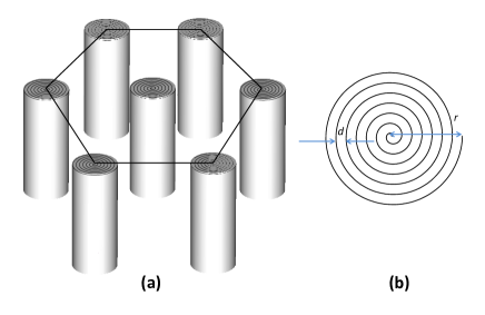
We assume an hexagonal lattice of CNS of lattice constant - see Fig. 1a. Figure 1b shows the top view of a CNS in the form of an archimedean spiral where the distance between two successive turns is nm (the same as the distance between two successive graphite layers) and the overall radius of the CNS is where is the number of turns of the CNS.
A lattice of CNS (miniaturized Swiss rolls) behaves as a uniaxial magnetic metamaterial 6 with an effective magnetic permeability along the CNS axis provided by 5
| (1) |
where is the surface coverage of a single CNS within a single unit cell. is the resonance frequency provided by
| (2) |
with being the vacuum speed of light and the loss factor given by 5
| (3) |
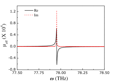
where is magnetic permeability of vacuum and the sheet resistance of a single layer of graphene. For undoped graphene 17, whilst for doped graphene can reach values as low as . 18 Either for doped or undoped graphene, these very low values of sheet resistance ensure a very narrow magnetic resonance that becomes narrower as the number of turns increases. Indeed, in Fig. 2 we show the effective permeability for a 2D array of CNS with . Each CNS contains turns of graphene giving a magnetic resonance at THz with FWHM of 3.2 GHz. The maximum value of the imaginary part of is above 12000 whereas the corresponding real part varies from -6000 up to 6000. These extremely high absolute values of and its ultra-subwavelength nature () are responsible for the excellent imaging properties of the CNS arrays shown below. The position of the magnetic resonance can be tuned at a desired spectral window by varying the number of turns of graphene layers, as demonstrated in Fig. 3.
A note on the applicability of the formula (1) is needed for the case of the CNS arrays. Eq. (1) is proved for a rolled-up meta-atom made of a perfectly conducting sheet. In order to meet this requirement for a graphenic CNS, it should contain enough turns of graphene so that the magnetic resonance of Eq. (2) lies within the THz regime. The dielectric function of graphene assumes very high absolute values in this frequency range 19, 20 and can therefore be safely considered as a perfect conductor. In the optical regime, the above formula should be revised in order to accommodate the inter- and intra-band transitions in graphene. However, in this case, the magnetic activity of a CNS array would deteriorate due to the high absorbance of graphene in the optical regime induced by the above transitions. 21, 22
To draw a comparison with the state of the art in similar designs, rolled-up metamaterials based on semiconductor microhelices and operating at about 4 THz have been realized, 23, 24 but the maximum reported value for the real part of is below 3, the corresponding FWHM about 1 THz, and the wavelength-to-structure ratio . Clearly, the resonance features of of the CNS array (Fig. 2) are superior to the above designs.

Next, we assess the imaging properties of a finite slab of the CNS array studied in Fig. 2. Due to the ultra-subwavelength nature of the CNS array, the effective-medium approximation is very accurate for our purpose, as has been demonstrated by direct comparison of the effective-medium theory with exact numerical calculations. 25 In this context, a finite slab of a 2D CNS array can be simulated as a homogeneous uniaxial medium with and provided by Eq. (1). In the calculations, we assume a slab of the CNS array of Fig. 2 of 12.1 m thickness. The transmission coefficient for the magnetic field of a transverse electric (TE) wave incident on a finite uniaxial magnetic slab of thickness is given by 8
| (4) |
where is the component of the incident wavevector which is parallel to the faces of the slab and is the component normal to the slab, i.e.,
| (5) |
For a wave decaying in free space, is an imaginary quantity because . Nonetheless, within a medium with and , becomes real corresponding to a propagating wave. This is the typical operation of a hyperbolic electric or magnetic metamaterial. When a free-space evanescent wave is incident on a slab of a hyperbolic metamaterial, it is transported through the slab without decay, or even with amplification if the imaginary part of is negative (canalisation effect). The CNS array studied here operates as a hyperbolic magnetic metamaterial in the region of negative real part of shown in Fig. 2. However, here we focus on a different regime, namely around the frequency where becomes maximum, approximating the theoretical limit of . In this case, we find from Eq. (5) that (since ) and all incident waves (both far- and near-field) propagate through the slab with the free-space wavenumber .
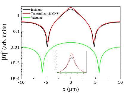
Figure 4 depicts the image of the magnetic field of a magnetic dipole (source), specifically, a current loop of 0.3 m radius. In the same figure, we show for comparison the magnetic field at the same distance from the source loop, in the absence of the CNS slab. Evidently, the slab of the CNS array transfers perfectly (with some amplification as well) the image from the magnetic dipole. Without the CNS slab, the image decays by more than two orders of magnitude. We note here that the value of 12.1 m for the thickness of the slab has been chosen so as to eliminate the reflection from the surface of the slab. Namely, for this thickness, ( is an integer) the transmission factor in Eq. (4) becomes unity. Of course, this is possible because inside the CNS slab becomes real (whereas in free space it is purely imaginary, as discussed above)
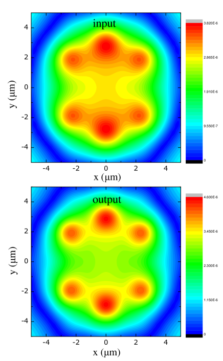
In Fig. 5 we demonstrate the imaging functionality of the CNS slab when multiple sources constitute a probe image incident on the same slab as in Fig. 4. Obviously, the image of the multiple sources is very efficiently transferred through the CNS slab, resulting in a clearer image of the sources due to the slight amplification of the magnetic field. In other words, the CNS slab not only operates as a THz endoscope of the magnetic field, but also offers a better resolution of the reconstructed image due to the slight amplification of the incident near field.
We note that we have considered an ordered array of CNS operating as uniaxial homogeneous medium. An isotropic homogeneous medium can be obtained if the CNS are not periodically positioned in space, for example, in random-packing fashion with arbitrary orientations of the CNS axis. In this case, the effective permeability will be isotropic (scalar quantity) and it will be again provided by Eq. (1). Moreover, when the CNS magnetic metamaterial is blended with randomly positioned and oriented long metallic nanorods which also exhibit electric response in the THz regime, a negative refractive index can be achieved.
We now address the issue of how an array of carbon nanoscrolls may form. There are two key facts that suggest the feasibility of this formation. First, vertical arrays of carbon nanotubes can be grown on various substrates with good control over the positions and inter-tube distance.27, 28 In turn, these arrays can serve as seeds for the formation of a lattice of CNS with graphene sheets wrapped around the nanotubes. The wrapping process has been described in previous computational studies 16, 29, 30 based on calculations with empirical force-field potentials. In the following we present the details of graphene wrapping around a single-wall carbon nanotube (SWCNT) using first-principles calculations.
The results were obtained with the density-functional theory code VASP,31 using projector-augmented waves,32 an energy cutoff of 350 eV for the plane-wave basis, and a generalized-gradient exchange-correlation functional. 33 We examined the wrapping of zig-zag graphene nanoribbons (GNR) with H-passivated ends around (6,6), (9,9) and (15,15) arm-chair SWCNTs, as well as the rolling of arm-chair GNRs around (9,0), (13,0) and (16,0) zig-zag SWCNTs. In the supercells used, one dimension is small and corresponds to the size of the unit cell of the carbon nanotube. Sampling of reciprocal space employed an 811 -grid with the first component related to the small dimension of real space.
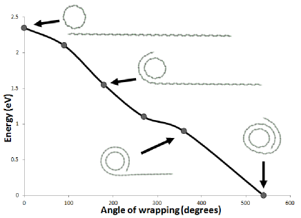
Figure 6 shows the decrease of energy when a a zig-zag GNR wraps around a (15,15) SWCNT. The monotonic drop of energy as the wrapping angle increases indicates that the CNS is formed readily for this particular nanotube. Similar results are obtained for rolling around the large diameter (16,0) SWCNT. In contrast, wrapping around the (6,6) and (9,0) nanotubes is not an exothermic process as the strain energy component becomes prohibitively large when the SWCNT diameter is small. The cases of (9,9) and (13,0) SWCNTs seem to be close to the threshold diameter that favors CNS formation. Notwithstanding the practical challenges, the computational results demonstrate the feasibility of growing arrays of carbon nano-scrolls around ordered seeds of carbon nanotubes that are not too small. Finally, we note that the magnetic response of a single SWCNT is irrelevant in our case since the resonance in is very weak than that of a single CNS and lies at much higher frequencies. 5
In conclusion, we have shown that one of the many conformations of single-layer graphene, namely, carbon nanoscrolls act as a magnetic metamaterial in the THz where naturally occurring magnetic materials are particularly scarce. Thanks to the small size of the carbon nanoscrolls compared to the operating THz wavelength (two orders of magnitude smaller), their spiral shape and the low sheet resistance of graphene, carbon nanoscrolls exhibit unrivaled imaging properties for magnetic sources in the THz regime. One of the possible routes to realize an array of carbon nanoscrolls is by self-folding of a single layer of graphene around a carbon nanotube, ordered arrays of which have already been realized in the laboratory. 27, 28
References
- 1 W. Cai and V. Shalaev, Optical Metamaterials, (Springer, New York, 2010).
- 2 L. Solymar and E. Shamonina, Waves in Metamaterials, (Oxford, Oxford, 2009).
- 3 C. Tserkezis, J. Phys.: Condens. Matter, 2009, 21, 155404.
- 4 T. Koschny, P. Markos, E. N. Economou, D. R. Smith, D. C. Vier, and C. M. Soukoulis, Phys. Rev. B, 2005, 71, 245105.
- 5 J. B. Pendry, A. J. Holden, D. J. Robbins, W. J. Stewart, IEEE Trans. Microw. Theory, 1999, 47, 2075.
- 6 M. C. K. Wiltshire, J. B. Pendry, I. R. Young, D. J. Larkman, D. J. Gilderdale, and J. V. Hajnal, Science, 2001, 291, 849.
- 7 M. C. K. Wiltshire, J. V. Hajnal, J. B. Pendry, D. J. Edwards, and C. J. Stevens, Opt. Express, 2003, 11, 709.
- 8 M. C. K Wiltshire, J. B. Pendry, W. Williams, and J. V. Hajnal, J. Phys.: Condens. Matter, 2007, 19, 456216.
- 9 C. Enkrich, M. Wegener, S. Linden, S. Burger, L. Zschiedrich, F. Schmidt, J. F. Zhou, T. Koschny, and C. M. Soukoulis, Phys. Rev. Lett., 2005, 95, 203901.
- 10 C. M. Soukoulis and M. Wegener, Nat. Phot. , 2011, 5, 523.
- 11 C. L. Cortes, W. Newman, S. Molesky, and Z. Jakob, J. Opt., 2012, 14, 063001.
- 12 V. P. Drachev, V. A. Podolskiy, and A. V. Kildishev, Opt. Express, 2013, 21, 15048.
- 13 I. V. Iorsh, I. S. Mukhin, I. V. Shadrinov, P. A. Belov, and Y. S. Kivshar, Phys. Rev. B, 2013, 87, 075416.
- 14 S. Amelinckx, D. Bernaerts, X. B. Zhang, G. Van Tendeloo, and J. Van Landuyt, Science, 1995, 267, 1334.
- 15 S. Braga, V. R. Coluci, S. B. Legoas, R. Giro, D. S. Salvao, and R. H. Baughman, Nano Lett., 2004, 4, 881.
- 16 Z. Zhang and T. Li, Appl. Phys. Lett., 2010, 97, 081909.
- 17 W. Cai, Y. Zhu, X. Li, R. D. Piner, R. S. Ruoff, Appl. Phys. Lett., 2009, 95, 123115.
- 18 S. De and J. N. Coleman, ACS Nano, 2010, 4, 2713.
- 19 A. Vakil and N. Engheta, Science, 2011, 332, 1291.
- 20 Y. Francescato, V. Giannini, and S. A. Maier, New. J. Phys., 2013, 15, 063020.
- 21 A. Y. Nikitin, F. Guinea, F. J. García-Vidal, and L. Martín-Moreno, Phys. Rev. B, 2011, 84, 161407.
- 22 E. Simsek, Opt. Lett, 2013, 38, 1437.
- 23 A. Rottler, M. Bröll, N. Gerken, D. Heitmann, and S. Mendach, Opt. Lett., 2011, 36, 4797.
- 24 S. Schwaiger, A. Rottler, and S. Mendach, Adv. Optoelec., 2012, 2012, 782864.
- 25 A. Demetriadou and J. B. Pendry, J. Phys.: Condens. Matter, 2009, 21, 326006.
- 26 C. Argyropoulos, N. M. Estakhri, F. Monticone, and A. Alù, Opt. Express, 2013, 21, 15037.
- 27 W. A. de Heer, W. S. Bacsa, A. Châtelain, T. Gerfin, R. Humphrey-Baker, L. Forro, and D. Ugarte, Science, 1995, 268, 845.
- 28 R. D. Bennett, A. J. Hart, and R. E. Cohen, Adv. Mater., 2006, 18, 2274.
- 29 N. Patra, Y. Song, and P. Kral, ACS Nano, 2011, 5, 1798.
- 30 Y. Cheng, X. Shi, N. M. Pugno, and H. Gao, Physica E, 2012, 44, 955.
- 31 G. Kresse and J. Furthmuller, Phys. Rev. B, 1996, 54, 11169.
- 32 P. E. Blöchl, Phys. Rev. B, 1994, 50, 17953.
- 33 J. P. Perdew, K. Burke, and M. Ernzerhof, Phys. Rev. Lett., 1996, 77, 3865.
- 34 S. Grimme, J. Comp. Chem., 2006, 27, 1787.