FACT - The First G-APD Cherenkov Telescope: Status and Results
Abstract
The First G-APD Cherenkov telescope (FACT) is the first telescope using silicon photon detectors (G-APD aka. SiPM). It is built on the mount of the HEGRA CT3 telescope, still located at the Observatorio del Roque de los Muchachos, and it is successfully in operation since Oct. 2011. The use of Silicon devices promises a higher photon detection efficiency, more robustness and higher precision than photo-multiplier tubes. The FACT collaboration is investigating with which precision these devices can be operated on the long-term. Currently, the telescope is successfully operated from remote and robotic operation is under development. During the past months of operation, the foreseen monitoring program of the brightest known TeV blazars has been carried out, and first physics results have been obtained including a strong flare of Mrk501. An instantaneous flare alert system is already in a testing phase. This presentation will give an overview of the project and summarize its goals, status and first results.
1 Introduction
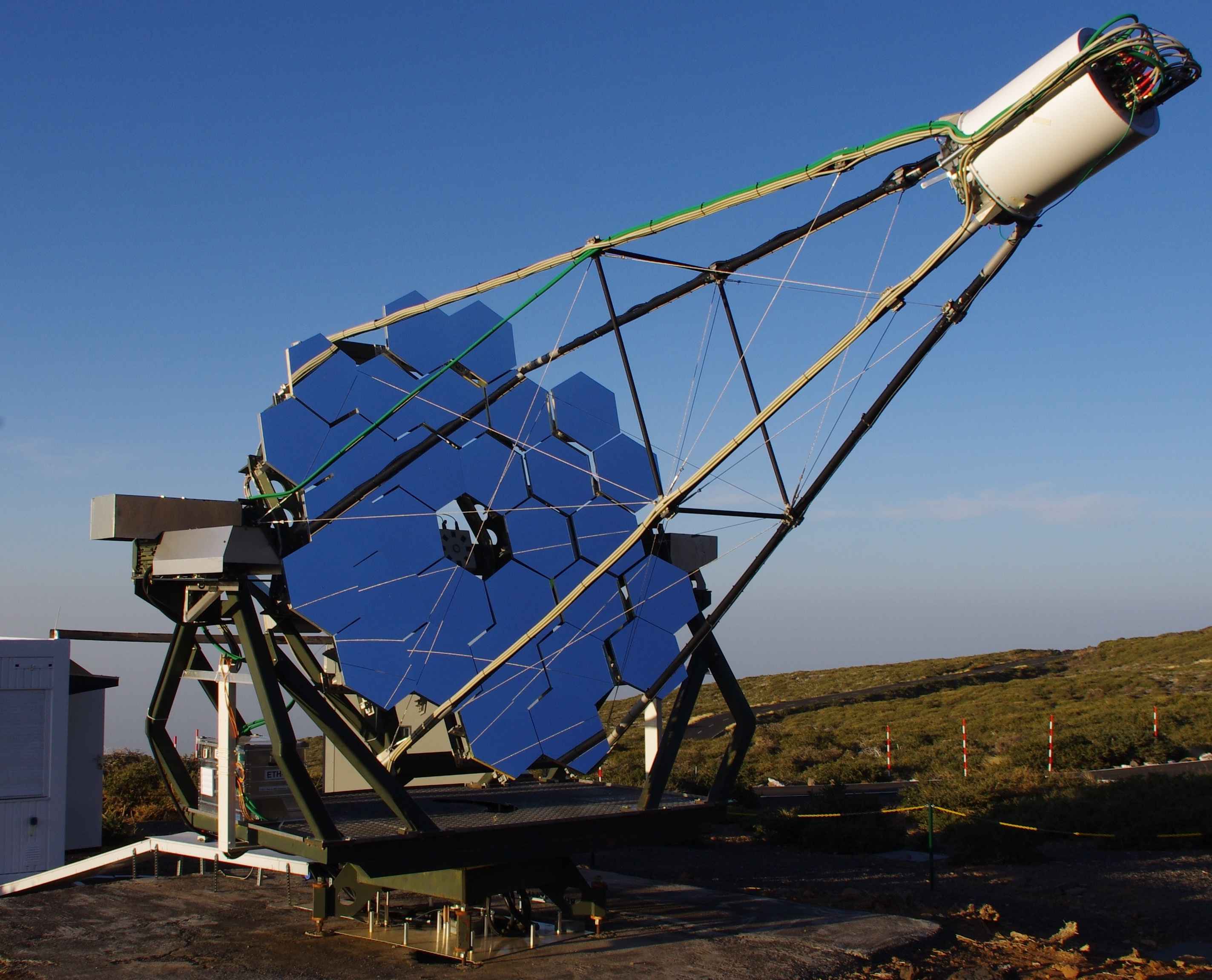
Since Oct. 2011, the FACT Collaboration is operating the First G-APD Cherenkov telescope [1] at the Observatorio del Roque de los Muchachos on the Canary Island of La Palma. The telescope’s camera is the first focal plane installation using Geiger-mode avalanche photo-diodes (G-APD) for photo detection. Comprising 1440 channels individually read out, each pixel has a field-of-view of 0.11° yielding a total field-of-view of 4.5°. The camera is installed on the mount of the former HEGRA CT 3 telescope. After replacement of the old disc shaped mirrors with refurbished hexagonal mirrors, it has now a total reflective surface of 9.5 m2. A picture of the telescope is shown in Fig. 1.
With this novel camera, silicon photo sensors have started to replace photo multiplier tubes (PMT) still widely used for photo detection. They offer a high gain ( to ) and are robust enough to be operated under moon light conditions. Their single photon counting capability, their compactness and their low operational voltage ( 100 V) simplifies the camera design. The photon detection efficiency (PDE) of commercially available G-APDs is already at the level of the best PMTs, and will still significantly improve in the future.
The challenge of the project is to understand and operate the silicon based photo sensors under changing environmental conditions, such as changing auxiliary temperature or changing photon flux from the diffuse night-sky background. A system to keep the G-APD response stable under these conditions has been developed.
The telescope is dedicated to long-term monitoring of the brightest known TeV blazars. These highly violent objects show variability on time scales of seconds to years. To study their behavior on the longer time scales, a complete data sample obtained from continuous measurements on long time scales is necessary.
2 System overview
The camera of the telescope is compiled from 1440 channels. Each channel is equipped with a G-APD (Hamamatsu MPPC S10362-33-50C) and a solid light concentrator. The solid light concentrators have the advantage, as compared to hollow ones, to feature a better compression ratio between entrance window and exit and thus balance the relatively small size of the sensors (9 mm2). Sensors, cones and a protective window were glued together using optical glue. All channels are individually read out by the Domino Ring Sampling chip (DRS 4). The data is transferred by a TCP/IP connection via Ethernet to a data acquisition PC. The summed signal of nine channels form a trigger signal which is discriminated by a comparator. Each trigger patch is divided in two bias voltage channels with four and five G-APDs, resp. Although all read out electronics was integrated into the camera, the bias voltage supply is located in the counting hut. Each bias voltage channel has its own current readout. The precision of the voltage application is 12 bit up to 90 V and 12 bit up to 5 mA for the current readout.
The total power consumption of the camera electronics during operation is about 570 W. About 100 W are dissipated in the supply lines and another 100 W due to the limited efficiency of the DC-DC converters, yielding a total of 370 W consumed by the electronics, 260 mW per channel.
To get rid of the waste heat produced by the camera electronics, a passive water cooling is applied. To avoid the sensors being heat up by the electronics, a thermal insulation is installed in between. In total, 31 temperature sensors measure the temperature of the sensor plane.
All details about the camera construction, the electronics and control software can be found in [1].
3 Status and achievements
3.1 Operation
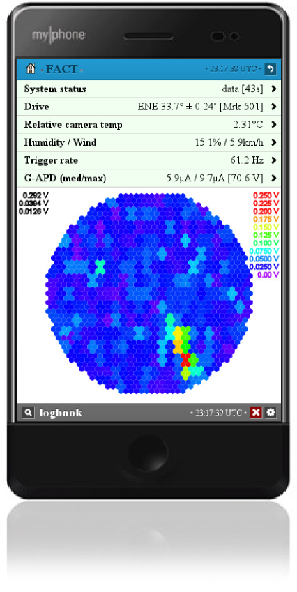
For a high duty cycle and consistent and stable data taking, a robust slow control and data acquisition software is needed. To avoid the need of shift crew on site, full remote operation must be possible. The camera is now operated since 20 months and its auxiliary hardware has been upgraded gradually, to allow for full remote control. This includes an interlock system, which purpose is to protect the camera from a cooling failure, Ethernet switchable 220 V plugs and the Ethernet access to all power supplies and a remote controllable lids. More details on that can be found in [2]. In parallel, a fully automatic control system has been developed. While all important parameters of the system are available via Web interface (see Fig. 2), the control of the system is achieved from a JavaScript engine reading the schedule from a database. Since a couple of weeks, this system is operating, and user interaction is usually only required in case of unexpected weather conditions.
Currently, a fully automatic analysis is also in the testing phase. It is applied on the data immediately after the data has been recorded and the file has been closed which typically happens every 5 min for physics data. The analysis takes about the same time than data taking and will allow prompt flare alerts for other telescopes in the near future.
3.2 Stability
One of the main goals of the project was the prove of the applicability of G-APDs during standard operation conditions. Since the gain and all other properties of G-APDs depend on their temperature and the voltage applied, a correcting element is necessary. By design, the temperature gradient in the focal plane is small enough allowing several G-APDs to be connected to a single bias voltage channel. In total, 31 temperature sensors installed in the focal plane allow to counteract temperature changes by adapting the applied bias voltage accordingly. The power supply of each sensor is equipped with a filter network of resistors. Due to the changing light conditions induced by changes of the atmospheric conditions or moon light, the current drawn by the G-APDs is varying inducing a voltage drop in the resistances. To correct for this voltage drop, the current of each channel is measured and the voltage corrected accordingly.
To measure the stability of the gain with these two feedback loops applied, three different methods are available:
External light pulser
An external temperature stabilized light pulser triggers the camera. Since its light yield is stable on average, the gain can directly be deduced from the average pulse height. However, the precision of this system measuring the gain of the G-APD is limited by the fact that also the transmission of the entrance window and the cones could change with time.
Dark count spectrum
A direct and mostly unbiased method to extract the gain, is the extraction of the dark count spectrum. It only depends on the performance of the G-APDs and the readout chain. Its drawback is that it can only be determined under light conditions, i.e. count rates, which still allow for extraction of single pulses. This is the case with closed lids or at dark time conditions.
Ratescans
To measure the stability of the gain in moon lit nights,
so called ratescans are used. Ratescans
measure the trigger response as a function of the applied trigger threshold.
While at low thresholds, the very high rates are dominated by random coincidences
of background photons, at high thresholds, the rate represents
the number of triggers from coincident light flashed, induced mainly
by hadronic showers. Although this method
depends on the performance of the whole system, it allows to measure the
response of the system even at the brightest light conditions.
To ensure an unbiased measurement, only ratescans taken during good
atmospheric conditions and weather conditions must be taken into account.
A more detailed discussion of this can be found in [9].
All three methods have been applied almost daily since the beginning of operation. This allows to compare the response at any possible light condition and all temperatures occurring over the seasons. All methods have shown consistently that with the applied feedback system, a stable gain up to full moon conditions can be achieved. From the dark count spectrum, a stability of better than 3% over time and 4% pixel-to-pixel variations was deduced. Currently, the limiting factor of the system is the calibration of the applied bias voltage which is under investigation and will be improved soon.
3.3 Data acquisition
The Ethernet connection between the forty readout boards and the data acquisition PC is routed over four Ethernet switches, two located in the camera and two located in the control room. In total, four Ethernet lines are available, one Ethernet line per ten boards. A total maximum transfer rate of about 1.9 Gbps is achieved. This is limited by the maximum throughput of 50 Mbps of each of the Ethernet-chips (Wiznet 5300) on-board of the forty data acquisition boards. The transfer rate corresponds to a trigger rate of 250 Hz for a readout window of 300 samples and 80 Hz for the readout of the full DRS pipeline (1024 samples).
3.4 Trigger threshold setting
One of the most important aspects during data taking is the correct setting of the trigger thresholds. To avoid high rates from random coincidences of background photons, the need to be set above the noise level. Since the noise level, mainly defined by the diffuse light from the night sky background, is not necessarily constant, some contingency is added to avoid strong rate fluctuations during data taking. At the same time, they must be set to as low as possible to achieve the lowest energy threshold and thus the highest integral sensitivity. Since the number of breakdowns in the G-APD, i.e. the number of detected photons, is proportional to the measured current, the rate induced from random coincidences as a function of the trigger threshold can directly be determined from the current. From ratescans taken at different light conditions over more than a year, a parametrization for the rate induced from background light and for the rate induced by hadronic showers under best conditions, was derived. Since several weeks, the trigger threshold of the system is now directly deduced from the measured current resulting in very stable data taking conditions. To allow for easy analysis, it is kept constant during every 5 min run.
3.5 Current and energy threshold prediction
To allow for an efficient schedule, the prediction of the system response under changing light conditions is mandatory. Therefore, the measured current has been correlated with moon conditions, i.e. moon brightness and zenith angle, which leads to a very precise prediction of the measured current. Since the trigger threshold is in the first order proportional to the light yield of the triggered shower, the change in energy threshold can directly be deduced. Including the change of the light yield with zenith angle, gives a very good estimate of the raise in energy threshold, i.e. loss in sensitivity, for each observation.
4 Physics results
Very soon after the first observations, first results could be presented [7]. From the measurements of the Crab Nebula, a sensitivity of 8% Crab in 50 h could be derived. This is based on the analysis of data taking during the first months of operation and based on an analysis primarily developed for MAGIC not yet necessarily optimized for the current system. From the rate of excess events an energy threshold between 400 GeV and 700 GeV can be derived taking the known spectrum of the source into account
The analysis, especially the automatic analysis, and first results are discussed in [8].
5 Conclusions
The camera of the First G-APD Cherenkov Telescope (FACT) has proven the applicability of silicon photo sensors (G-APD) in focal plane installations, in particular as detectors in Cherenkov telescopes. The camera is now in operation since more than one and a half years, and although there were hardware problems during that time, none of the was related to the G-APDs at all. So far, no decrease in performance could be detected. Neither any hint for aging of the G-APDs nor of the transmission of cones and window has been found.
With different types of measurements, it was shown that a stability to on the few percent level, independent of temperature and light conditions can be achieved. Further improvements are expected by an improvement of the bias voltage calibration.
An important result derived from the current study is that the application of a feedback system which keeps the G-APD’s bias voltage constant, renders the need for an external calibration device obsolete. The combination of the extraction of the dark count spectrum and the current measurement, is enough for the operation of such a device.
Recently, Hamamatsu presented a new generation of G-APD sensors with significantly lower dark count rates, significantly reduced optical crosstalk and significantly reduced afterpulse probability, expected to be available on the market within the next weeks [10].
Although, it was shown that these improvements are not obligatory for the operation in a Cherenkov telescope, especially the reduction in optical crosstalk guarantees that the influence on image reconstruction is negligible.
Not only, can the FACT telescope serve as an ideal instrument for long-term monitoring of bright blazars, the application of G-APDs in focal plane installations will significantly reduce construction and installation costs and improve stability of operation. This will yield a significantly impact on future projects like The Cherenkov Telescope Array (CTA) and makes small telescopes for monitoring purposes affordable.
Acknowledgment
The important contributions from ETH Zurich grants ETH-10.08-2 and ETH-27.12-1 as well as the funding by the German BMBF (Verbundforschung Astro- und Astroteilchenphysik) are gratefully acknowledged. We thank the Instituto de Astrofisica de Canarias allowing us to operate the telescope at the Observatorio Roque de los Muchachos in La Palma, the Max-Planck-Institut für Physik for providing us with the mount of the former HEGRA CT 3 telescope, and the MAGIC collaboration for their support. We also thank the group of Marinella Tose from the College of Engineering and Technology at Western Mindanao State University, Philippines, for providing us with the scheduling web-interface.
References
- [1] H. Anderhub et al. (FACT Collaboration), 2013, JINST 8 P06008 [arXiv:1304.1710].
- [2] A. Biland et al. (FACT Collaboration), these proc., ID 708.
- [3] T. Bretz et al. (FACT Collaboration), these proc., ID 683.
- [4] FACT Collaboration, in prep.
- [5] T. Bretz et al. (FACT Collaboration), these proc., ID 720.
- [6] M. Koetig et al. (FACT Collaboration), these proc., ID 695.
- [7] Bretz, T. et al. (FACT Collaboration) 2012, AIPC, 1505, 773.
- [8] D. Dorner et al. (FACT Collaboration), these proc., ID 686.
- [9] D. Hildebrand et al. (FACT Collaboration), these proc., ID 709.
- [10] http://kicp-workshops.uchicago.edu/ieu2013.