Space-time coupling in the up-conversion of broadband down-converted light
Abstract
We investigate the up-conversion process of broadband light from parametric down-conversion (PDC), focusing on the spatio-temporal spectral properties of the sum-frequency generated (SFG) radiation. We demonstrate that the incoherent component of the SFG spectrum is characterized by a skewed cigar-shaped geometry in space-time due to the compensation of spatial walk-off and group-velocity mismatch between the fundamental and the generated SFG fields. The results are illustrated both by a theoretical modeling of the optical system and by experimental measurements.
Version
Introduction
The process of sum frequency generation occurring in a crystal has often been used in ultra-fast nonlinear optics experiments for probing the spatio-temporal structure of femtosecond pulses. In particular, the three-dimensional mapping of ultrashort complex pulses minardi2004 ; trull2004 and the observation of the spatio-temporal dynamics of Kerr media filamentation majus2010 has been obtained with this method.
Recent works dayan2005 ; peer2005b ; ribeiro2006 ; harris2007 ; dayan2007 have shown that sum-frequency generation represents also a resource for exploring and manipulating the entanglement properties of a broadband PDC source, as well as for applications in quantum information processing. For example, spectrally engineered SFG has been proposed as a tool for selecting broadband quantum modes (Schmidt modes) from the ultra-fast multi-mode state generated by PPLN waveguides silberhorn2011 .
Recently our research group applied the SFG technique for investigating the whole spatio-temporal structure of the PDC biphoton correlation brambilla2012 ; jedr2012a ; jedr2012b in order to reveal its nontrivial geometry in the space-time domain studied in gatti2009 ; caspani2010 ; brambilla2010 . In that experiment, a quasi-stationary pump pulse with a broad transverse cross-section was injected in a first crystal and the generated PDC light was imaged into an identical crystal tuned for the same phase-matching conditions where the SFG process takes place. A perfect tuning between the two crystals allows the partial reconstruction of the original pump beam through the inverse PDC process, i.e. SFG from conjugate mode pairs jedr2011 . In such a detection scheme, the SFG crystal is used as an ultra-fast optical correlator and we showed that the coherent component of the SFG radiation is able to provide detailed information on the biphoton correlation function characterizing the PDC source.
In this work we shall focus on the spatio-temporal properties of the incoherent component of the up-converted PDC field. In addition to the SFG coherent process which leads to the reconstruction of the original pump beam, the random up-conversion of photon pairs that do not belong to twin modes generates SFG radiation over a much broader range of spatio-temporal modes. This incoherent process, though negligible compared to the coherent process as long as the PDC source operates in a coincidence count regime dayan2005 , becomes relevant at high parametric gains, i.e when the mean number of PDC photons per mode is larger than unity. We investigate the spatio-temporal properties of the field produced through this incoherent process, showing how propagation effects inside the SFG crystal rapidly selects the spatio-temporal modes undergoing the up-conversion process in a non-trivial way, leading to a coupling between the spatial and the temporal frequencies. We shall demonstrate how the SFG incoherent spectrum displays a nontrivial skewed geometry in the spatio-temporal frequency domain deriving from the interplay of group-velocity mismatch (GVM) and spatial walk-off between the fundamental (PDC) field and the up-converted one (SFG radiation).
In Sec.I we illustrate the experimental scheme implemented for the measure of the spatio-temporal spectrum of the up-converted PDC field. The theory developed in Sec.II, valid within the quasi-stationary plane-wave pump approximation (PWPA), allows to obtain approximate expression for the coherent and the incoherent spectra and provide a physical insight into the experimental observation. The results obtained from a 3D+1 numerical modeling of the optical system are presented in Sec.IV and interpreted in the light of the PWPA theory. The results of the experiment are reported in Sec.V.
I Scheme of the measurement
The conditions of the experiment are similar to those reported in jedr2011 . The PDC radiation is generated in a pulsed regime with high parametric gain by a type I BBO crystal pumped at 527.5nm (e-oo phase-matching). The crystal is cut for collinear emission at the degenerate wavelength nm. The optical setup is shown in Fig.1. The pump beam injected in the PDC crystal is a ps Gaussian pulse with a 500 micrometers transverse beam waist. The pump is then subtracted with a glass filter (transmission bandwidth 750-1300nm) and the PDC field is imaged at the entrance face of the SFG crystal where the up-conversion process takes place. The 4-f imaging device is built with two achromatic parabolic mirrors rather than with lenses, in order to minimize dispersion between the two crystals. As demonstrated in jedr2011 ; jedr2012a , it is capable of reconstructing the PDC field at the SFG crystal input face preserving both its amplitude and its phase over a very broad range of temporal and spatial frequencies. The temporal and angular bandwidths are respectively on the order of nm and .
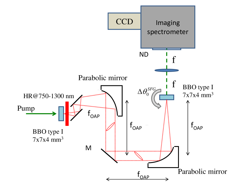
The spatio-temporal features of the output field from the SFG crystal are analyzed in the far-field, by means of of an imaging spectrometer (IS) that collects the photons in the focal plane of a 20 cm focal length lens. A CCD camera (Roger Scientific) is placed at the very output of the spectrometer (LOT Oriel) in order to record the resulting spectral images. (see Fig.1).
II Theory - spectral characterization of the up-converted PDC light
We introduce the theoretical framework that allows the interpretation of spectral measurements obtained from the optical scheme illustrated in the previous section. A detailed derivation of the PWPA results illustrated in the next subsection can be found in brambilla2012 .
The results that follow hold in the limit where the PDC pump beam can be approximated by a monochromatic plane-wave of frequency propagating along the -axis direction, a condition which is roughly satisfied in our experiment. The detailed treatment can be found in brambilla2012 .
For the type I BBO used in our experiment, the pump is extraordinarily polarized while the down-converted field is ordinarily polarized (e-oo phase-matching), so that the refractive index of the pump depends on its direction angle with respect to the crystal axis , while the PDC field refractive index is isotropic. We take into account the possibility that the two crystals are not perfectly tuned, i.e. we consider conditions where the orientation angles of the two crystals with respect to the pump axis, denoted by and respectively, are slightly different. The reference -vector of the extraordinary wave can thus differ in the first (cr=PDC) and in the second crystal (cr=SFG).

For briefness we shall use the shorthand notation for denoting a Fourier mode of temporal frequency and transverse wave-vector , with the reference frequencies denoting either the pump frequency when dealing with the extraordinarily polarized up-converted field, or the degenerate frequency when dealing with the ordinarily polarized PDC field. Within the plane-wave pump approximation (PWPA), the input-output transformation for the PDC field operators is best written in the Fourier domain where it takes the simple form
| (1) |
where and are the Fourier transform of the field operator envelopes (carrier frequency at the crystal input and output face respectively. The explicit expression of the gain functions and can be found e.g. in kolobov99 ; brambilla2004 . Here we notice that the dependence on the spatio-temporal frequencies occurs only through the PWP phase-matching function
| (2) |
where denotes the wave-number of the extraordinarily polarized plane-wave pump, is the wavevector longitudinal component for the ordinary PDC mode . All the properties of the PDC light are described by the following second-order field correlation functions
| (3a) | |||
| (3b) | |||
In particular, the PDC spatio-temporal spectrum
| (4a) | |||
| (4b) | |||
gives the PDC photon number distribution in the spatio-temporal frequency domain. The dimensionless parametric gain , proportional to the pump amplitude, the PDC crystal length and the effective coefficient, determines the number of photons for perfectly phase-matched mode, for which .
The other quantity of interest is the spectral probability amplitude (also called biphoton amplitude) of down-converting a pair of photons in the phase-conjugated modes and
| (5) |
For the PDC gain considered in the experiment, only a small fraction of the injected PDC light is up-converted in the second crystal through SFG, and the propagation equation describing the SFG process can be solved accordingly within a perturbative approach. We obtain in this way the following expression linking the operators of the SFG field at the crystal output plane, , to those of the PDC field imaged at the input plane, :
| (6) |
where denotes the SFG crystal length, the input envelope operator at the career frequency is taken in the vacuum state (it is assumed that the PDC pump field is completely subtracted by the glass filter shown in Fig.1), and
| (7a) | |||
| (7b) | |||
is the probability amplitude density describing the SFG process: its square modulus is proportional to the probability for a pair of photons in the fundamental mode and to be up-converted into the second-harmonic mode . This up-conversion probability is non negligible only for those mode pairs for which the phase-mismatch accumulated in the SFG crystal is sufficiently small. Both the coupling constant in Eq.(7a), and the PDC parametric gain are proportional to the effective coefficient of the crystal for the chosen phase-matching conditions brambilla2012 .
In Ref.brambilla2012 we show that the power spectrum of the up-converted SFG field evaluated at the output face of the SFG crystal can be written as the sum of a coherent and an incoherent component, the former being given by
| (8) |
while the incoherent component is defined through the relation
| (9a) | |||
| (9b) | |||
The coherent SFG component (8) originates from the up-conversion of pairs of phase-conjugate PDC modes, and , into the original plane-wave pump mode , that leads to the partial reconstruction of the original coherent pump beam jedr2011 ; dayan2007 . The efficiency of this coherent process is indeed determined by the PWP phase-matching function inside the the SFG crystal, i.e.
| (10) |
It has been demonstrated in previous works, both theoretically brambilla2012 and experimentally jedr2012a ; jedr2012b , that the whole X-shaped structure of the PDC correlation function in the space-time domain can be retrieved by monitoring the coherent SFG component while performing a careful manipulation of the spatial and the temporal degrees of freedom of the PDC field between the two crystals.
We shall now focus on the incoherent component of the spectrum (9b), the main target of our investigation, which derives from the up-conversion of pairs of photons which do not belong to phase-conjugate modes and give rise to the speckle-like background observed in the experiments reported in Refs.jedr2011 ; jedr2012a ; jedr2012b . As it can be inferred from Eq.(9b), it reduces to the self-convolution of the PDC spectrum in the limiting case where the SFG crystal is extremely thin, since the SFG probability amplitude can be replaced by unity under the integral sign in Eq.(9b) when . We shall verify, however, that propagation effects inside the SFG crystal become relevant as soon as realistic lengths of the SFG crystal are considered, giving the SFG incoherent spectrum a peculiar skewed geometry in the spatio-temporal frequency domain, thus highlighting the role of interplay between space and time.
III Evaluation of the incoherent SFG spectrum
More insight about the structure of the incoherent spectral component (9) can be gained by close inspection of the phase-matching functions in the SFG crystal (7b). With this goal in mind, we separate the longitudinal -vector component of the ordinary PDC field into its even and odd parts
| (11) |
We notice that the even part can be expressed in terms of the PWP phase-matching function (2)
| (12) |
while the odd part can be expanded in odd powers of and
| (13) |
where we used the shorthand notations , , , etc. and we took into account the independence of the PDC dispersion relation on the propagation direction (i.e. on the transverse wave-vector ). By neglecting the cubic terms in Eq.(13) (the third order dispersion and the term ), the SFG phase-matching function that enters into the incoherent spectrum expression (9b) can be cast into the form
| (14) |
with
| (15) |
This result is very useful because it allows us to rewrite the incoherent SFG spectrum (9b) in the form
| (16b) | |||||
| (16c) | |||||
The last expression involves a rather rough approximation based on the observation that the presence of and under the integral in Eq. (16b) forces and in the whole integration region, due to the fact that the PDC spectrum is strongly peaked around the region where phase-matching occurs. Strictly speaking it should be valid only in the limit , however it turns out to give a good description of the SFG spectrum also when the two crystals have similar lengths.
Assuming the validity of this approximation, the SFG spectrum takes thus the factorized form
| (17) |
where the first factor
| (18) |
describes the effect of propagation in the SFG crystal and determines the overall shape of spectrum. The second factor, which does not depend on the SFG crystal parameters,
| (19) |
is the self-convolution of the PDC spectrum given by Eq.(4) and acts only as a slow modulation. This can be clearly seen in the numerical example of Fig.3, which shows the functions in play in the plane (along the walk-off direction) in the case of two type I BBO crystals aligned for collinear phase-matching at degeneracy.

The first plot shows the PDC spectrum with its characteristic bandwidths and (see the discussion at the end of this section). The second plot is the self-convolution of such a spectrum, i.e. the function appearing in the SFG spectrum in Eq.(17). The third plot displays with the corresponding bandwidth and . The last plot shows the SFG spectrum evaluated from the full expression (9b), without using the factorized approximation (17). It indeed demonstrates that the SFG spectrum is roughly the product of the functions and , in agreement with Eqs.(17)-(19), and that the shape of the spectrum is mainly determined by the function .
We thus see that the spectrum in the -plane has a skewed cigar-like shape. In the full 3D Fourier domain this corresponds to a volume centered around a skewed surface determined by the region in -space where takes its maximum value, i.e.
| (20) |
A closer insight can be gained by exploiting the following approximation for the longitudinal -vector component of the ordinary and extraordinary fields
| (21a) | |||
| (21b) | |||
where the walk-off angle and the -vector derivative and of the extraordinary field are meant to be evaluated at along the optical axis (the -axis is taken along the walk-off direction). By substituting Eq.(21b) into Eq.(15) we obtain the approximated expression
| (22) |
where
| (23) |
determines the widths of in the spatial and temporal frequency domains respectively, as indicated in the example of Fig.3c. For small and the linear terms in Eq.(22) are the dominant ones: they describe the effect of GVM and spatial walk-off between the PDC and SFG fields in the incoherent up-conversion process, and giving respectively the typical transverse separation and the time delay between the ordinary (PDC) and the extraordinary (SFG) fields after a propagation distance equal to the SFG crystal length .
Neglecting the quadratic terms with respect to the linear ones, the surface is close to the skewed plane
| (24) |
Notice that the constant term, as we shall see in the next section, is non vanishing only when the two crystals are tuned for different phase-matching conditions. We see from relation (24) that incoherent upconversion from PDC occurs only for those spatio-temporal modes for which the GVM between the fundamental and the up-converted light is compensated by their spatial walk-off.
We conclude this section by observing that, using the same quadratic approximation (21), the phase-matching function in the PDC crystal can be written as
| (25) |
where the introduced bandwidths associated with GVD and diffraction
| (26) |
give an estimate of the spectral widths of both and along the temporal and the spatial frequency axes respectively (as indicated in the plot of Fig.3a). Unless the SFG crystal is extremely thin, the typical variation scale (, of are much shorter than (, (see Fig.3a,c). This is the reason why the self-convolution of the PDC spectrum (19) acts as a slow modulation, on the scales (, , while defines the overall shape of the incoherent spectrum. More precisely, we find that becomes narrower than for
| (27) |
in the spatial frequency domain, and for
| (28) |
in the temporal frequency domain, the given numerical values being estimated for the 4mm type I BBO crystal used in our experimental setup. For exceeding those values, spatial walk-off and GVM becomes the dominant processes affecting the SFG incoherent emission, as the ratio and decrease below unity scaling as .
IV Incoherent spectrum vs SFG crystal length and angular tuning
In this section we give an overview of the incoherent spectrum behaviour with respect to different phase-matching conditions in the SFG crystal, obtained by changing either its length or its relative orientation with respect to the PDC crystal. The numerical results are obtained with a full 3D+1 modeling of the experiment jedr2011 ; jedr2012a ; jedr2012b in order to achieve a realistic description of the optical system.
The generation of the broadband PDC field is described by stochastic simulations in the framework of the Wigner representation (see e.g. brambilla2004 ; brambilla2012 ), which take into account both the finite cross section and duration of the pump pulse and the phase-matching conditions inside both crystals (the Sellmeier dispersion relation for the BBO crystal found in boeuf2000 are used). The waist and the duration of the injected Gaussian pump pulse are respectively m and ps, the PDC gain parameter corresponds to a pulse energy close to . We verified that the PWPA model provides similar results for the chosen pump parameters.
Figure 4 shows the evolution of the SFG spectrum for increasing lengths of the SFG crystal . In each single stochastic realization the incoherent component of the spectrum appears as a speckle-like pattern 111Ensemble averages performed by repeating the simulation would provide the correct quantum mechanical mean values for the spectrum in the framework of the Wigner representation as described e.g. in brambilla2004 . However, the required CPU time would be prohibitive and would not add more insight to the description. (see brambilla2012 for more details), while the PWPA result (9) provides the mean value of the spectrum (see e.g. Fig.3d). When the SFG crystal is sufficiently thin, as in Fig.4a, conditions (27) and (28) are not satisfied and both spatial walk-off and GVM are almost ineffective. In this limit the SFG incoherent spectrum reproduces the shape of the PDC spectrum self-convolution (19) in agreement with the PWPA model result presented in the previous section (this can also be inferred by comparing Fig.4a and fig.3b). By increasing , we find the predicted transition to the much narrower cigar-shaped spectrum skewed in the walk-off plane, close to the PWPA result shown in Fig.3d [its orientation in the -plane is given by Eq.(24)].

Notice also that the 3D+1 model includes the coherent component of the SFG spectrum: the narrow peak centered at , clearly visible in the surface plots (bottom panel), corresponds indeed to the coherent reconstruction of the original pump pulse predicted by the PWPA theory [see Eq.(8)]. For a narrow band pump field spectrum, the coherent peak height is more than four order of magnitude larger than the widely spread incoherent component. For this reason the plots in Fig.4 have been truncated to of the coherent peak value in order to display the incoherent component distribution. An analytical estimation of the visibility of the coherent SFG component against the incoherent contribution as a function of the pump beam parameters and the PDC gain will be given elsewhere nw .

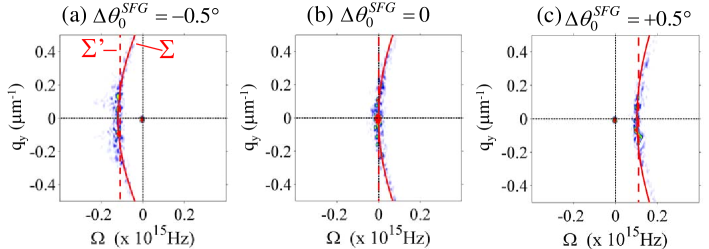
We investigated the effect of a small tilt angle of the SFG crystal with respect to the PDC crystal. The PDC crystal is oriented for collinear PM as in the previous examples, while the SFG crystal is tilted by the angles (a) ,(b) and (c) . Figures 5 and 6 show the SFG spectrum obtained with the 3D+1 model, evaluated respectively in the plane parallel and orthogonal to the walk-off direction. As illustrated in the next section, this corresponds to the two possible configurations of the imaging spectrometer (IS) implemented in the experiment, the first providing a measure of , the second a measure of . In the first configuration where is displayed, the incoherent spectrum is skewed in the -plane along the direction direction of (red dashed line in the density plots), as predicted by the PWPA model (24). In the second case, where spatial walk-off does not play any role, the temporal frequencies of the incoherent component have the same offset from pump frequency for a large range of spatial frequencies. This offset is roughly given by as can be inferred by setting into Eq.(24). Accordingly, the central wavelength of the incoherent component is
| (29) |
The red solid line shown in the figures corresponds to the more precise relation between the spatial and temporal frequencies given by Eq.(20), which includes the slow varying quadratic terms. The latter are responsible of a slight concavity of the surface toward shorter wavelengths, a feature which fits well the shape of the incoherent spectrum obtained with the 3D+1 model over a broad range of spatial frequencies (see in particular Fig.6a).
It is worth noticing that the coherent SFG component rapidly decreases with the mistuning between the two crystals, while the incoherent peak remains almost unaffected. This behaviour is shown in Fig.7, where the number of photons of the two components are plotted as a function of . The coherent up-conversion process, in contrast to the incoherent process, is indeed strongly phase-sensitive and rapidly loose efficiency when the two crystals are not perfectly tuned. As shown in brambilla2012 , the number of coherent SFG photons is reduced by about a factor 10 when the tilt angle exceeds the critical value
| (30) |
which is close to degree for the chosen BBO parameters (, mm). Despite that, even for a tilt angle as large as one degree (see Fig.7) the intensity of the coherent component remains significantly larger than that of the incoherent component due to concentration of all the coherent SFG photons in a single mode corresponding to the original pump (which is strongly focused in the Fourier domain).

V Experimental results
The aim of the experimental work was to characterize the spatio-temporal far-field spectrum (in the plane) of the SFG radiation, and to verify the predicted behaviour of the incoherent component as a function of the angular mistuning between the PDC crystal and the SFG crystal. To this end the output radiation from the SFG crystal was analyzed by means of an imaging spectrometer (grating with lines/mm), whose entrance vertical slit (with respect to the optical bench) was placed in the Fourier plane of a cm focal length lens. The spectra were recorded in the walk-off plane and in the plane orthogonal to walk-off. Because of the geometry of our system and the crystal axis orientation, the vertical plane in the laboratory frame corresponded to the plane orthogonal to walk-off. In order to detect the spectra in the walk-off plane, the radiation reconverted from the SFG crystal was tilted by 90 degrees by means of two mirrors aligned in a periscope configuration.

The upper panel reported in Fig.8 (gray scale plots) shows typical single shot spectra of the SFG radiation recorded (a) in the plane parallel to walk-off and (b) in the orthogonal plane. The central coherent peak in the collinear direction is evident, and the features of the incoherent component in the -plane are in agreement with the theory. The bottom panel shows the corresponding spectra obtained with the 3D numerical model. The experimental spectra exhibits the skewed geometry predicted by theory, which originates from the compensation of spatial walk-off and GVM.
Figure 9 illustrates the behaviour of the SFG spectrum when the second crystal is rotated with respect to the first one by an angle ; in particular it reports the SFG spectrum in the two different configurations by varying the tuning angle from up to by steps of . Fig.10 displays a more detailed comparison between the theory and the experiment: the square symbols with the error bar reports the central wavelength of the incoherent component along the collinear direction (). The solid line in the same figure is obtained from the PWPA model by solving numerically the equation for different tuning angles , being given by Eq.(15). The agreement between theory and experiment is very good although not perfect, especially at large mistuning angles. However, such a quantitative agreement between theory and experiment is beyond the scope of this work, whose goal is mainly to demonstrate the characteristic geometry of the spectrum of the SFG light originating from incoherent upconversion of PDC light.


VI Conclusions
In this work we investigated the up-conversion process of broadband PDC radiation, focusing on the spatio-temporal spectral properties of its incoherent component.
We have shown that as soon as the SFG crystal is longer than a few hundreds micrometers, the phase-matching mechanism selects the spatio-temporal frequencies of the incoherent SFG radiation in a non trivial way: the spectrum is characterized by a skewed cigar-like shape in the spatio-temporal Fourier domain which derives from the interplay of group-velocity mismatch and spatial walk-off between the PDC field and the SFG field. As for many other nonlinear optical processes, these features are a manifestation of the space-time coupling that occurs because of phase-matching. We can cite the closely related examples of the skewed coherence along space-time trajectories predicted in three and four-wave mixing processes picozzi2002 and of the X-shaped spatio-temporal coherence of twin beams jedr2006 . Other relevant examples are the X-shaped quantum correlation in space-time of twin beams gatti2009 ; caspani2010 ; brambilla2010 ; jedr2012a ; jedr2012b and the macroscopic X-waves generated in quadratic media ditrapani2003 or in four-wave mixing process related to a cubic nonlinearity couairon2006 .
It is only in the limit where the SFG crystal is extremely thin that the generated SFG intensity is simply proportional to the square of the injected PDC intensity. This limit corresponds to situations in which phase-matching in the second-crystal does not play a significant role, so that the SFG spectrum coincides with the self-convolution of the PDC spectrum.
We have also studied the behaviour of the SFG spectrum with respect to small angular mistuning between the PDC and the SFG crystals. For increasing values of the angular mistuning, we observe a progressive displacement of the incoherent spectrum with respect to the wavelength of the coherent peak, a property which could provide a useful tool for optimizing the visibility of twin beam correlation measurements.
These results have been illustrated by means of a semi-analytical and a numerical model of the optical system, and have been fully confirmed by the experimental measurements.
Acknowledgements.
This work was realized in the framework of the Fet Open project of EC 221906 HIDEAS.References
- (1) M. Potenza, S. Minardi, J. Trull, G. Blasi, D. Salerno, Arunas Varanavicius, A. Piskarskas, and Paolo Di Trapani, Opt. Comm. 229, 381 (2004).
- (2) J. Trull, O. Jedrkiewicz,P. Di Trapani, A. Matijosius, A. Varanavicius, G. Valiulis, R. Danielius, E. Kucinskas, A. Piskarskas, and S. Trillo, Phys. Rev. E, 026607 (2004).
- (3) D. Majus, V. Jukna, G. Tamosauskas, G. Valiulis, and A. Dubietis, Phys. Rev. A 81, 043811 (2010).
- (4) Barak Dayan, Avi Peer, Asher A. Friesem, and Yaron Silberberg Phys. Rev. Lett. 94, 043602 (2005).
- (5) Avi Peer, Barak Dayan, Asher A. Friesem, and Yaron Silberberg Phys. Rev. Lett. 94, 073601 (2005).
- (6) D. S. Ether, P. H. Souto Ribeiro, C. H. Monken, and R. L. de Matos Filho Phys. Rev. A 73, 053819 (2006).
- (7) S. E. Harris, Phys. Rev. Lett. 98, 063602 (2007)
- (8) B. Dayan, Phys. Rev. A 76, 043813 (2007).
- (9) A. Eckstein, B, Brecht, and C. Silberhorn, Opt. Expr. 19 13770 (2011).
- (10) E. Brambilla, O. Jedrkiewicz, L.A. Lugiato, and A. Gatti, Phys. Rev. A 85, 063834 (2012).
- (11) O. Jedrkiewicz, J.-L. Blanchet, E. Brambilla, P. Di Trapani, and A. Gatti, Phys. Rev. Lett. 108, 253904 (2012).
- (12) O. Jedrkiewicz, A. Gatti, E. Brambilla, and P. Di Trapani, Phys. Rev. Lett. 109, 243901 (2012).
- (13) A. Gatti, E. Brambilla, L. Caspani, O. Jedrkiewicz, and L.A. Lugiato, Phys. Rev. Lett. 102, 223601 (2009).
- (14) L. Caspani, E. Brambilla, and A. Gatti, Phys. Rev. A 81, 033808 (2010).
- (15) E. Brambilla, L. Caspani, L.A. Lugiato, and A. Gatti, Phys. Rev. A 82, 013835 (2010).
- (16) O. Jedrkiewicz, J.L. Blanchet, A. Gatti, E. Brambilla, and P. Di Trapani, Opt. Expr., 19, 12903 (2011).
- (17) E.Brambilla, A.Gatti, M.Bache, and L.A. Lugiato, Phys. Rev. A 69, 023802 (2004).
- (18) M.I. Kolobov, Rev. Mod. Phys. 71, 1539 (1999).
- (19) V. G. Dmitriev, G. ,G. Gurzadyan, D. N. Nikogosyan, Handbook of nonlinear optical crystals, Springer series in optical sciences, Springer-Verlag, Berlin (1991); N. Boeuf et al., Optical Engineering, 39, 1016 (2000).
- (20) A. Gatti and E. Brambilla, in preparation
- (21) O. Jedrkiewicz, A. Picozzi, M. Clerici, D. Faccio and P. Di Trapani, Phys. Rev. Lett. 97, 243903 (2006).
- (22) A. Couairon, E. Gaizauskas, D. Faccio, A. Dubietis, and P. Di Trapani, Phys. Rev. E 73, 016608 (2006).
- (23) A. Picozzi and M. Haelterman, Phys. Rev. Lett. 88, 083901 (2002).
- (24) P. Di Trapani, G. Valiulis, A. Piskarskas, O. Jedrkiewicz, J. Trull, C. Conti, and S. Trillo, Phys. Rev. Lett. 91, 093904 (2003).