Thickness Dependent Carrier Density at the Surface of SrTiO3 (111) Slabs
Abstract
We investigate the surface electronic structure and thermodynamic stability of the SrTiO3 (111) slabs using density functional theory. We observe that, for Ti-terminated slabs it is indeed possible to create a two-dimensional electron gas (2DEG). However, the carrier density of the 2DEG displays a strong thickness dependence due to the competition between electronic reconstruction and polar distortions. As expected, having a surface oxygen atom at the Ti termination can stabilize the system, eliminating any electronic reconstruction, thereby making the system insulating. An analysis of the surface thermodynamic stability suggests that the Ti terminated (111) surface should be experimentally realizable. This surface may be useful for exploring the behavior of electrons in oxide (111) interfaces and may have implications for modern device applications.
pacs:
73.40.-c, 31.15.E-, 71.28.+d, 81.05.ZxI Introduction
Since the discovery of a two-dimensional electron gas (2DEG) at the LaAlO3/SrTiO3 (LAO/STO) interface, Ohtomo and Hwang (2004) oxide heterostructures have attracted renewed attention. Hwang et al. (2012) In addition to having high carrier densities Seo et al. (2007) ( /cm2) with mobilities as high as cm2/(Vs), Ohtomo and Hwang (2004) such a 2DEG is also the host to a wide variety of electronic phenomena, including superconductivity, Reyren et al. (2007) magnetism, Brinkman et al. (2007) and Rashba spin-orbit coupling. Ben Shalom et al. (2010); King et al. (2012) These phenomena, together with the demonstrated tunability of interface conductivity through electric, Thiel et al. (2006); Cen et al. (2008) chemical and photosensitive means, Meevasana et al. (2011) offer promising potential for device applications with novel functionality. Mannhart and Schlom (2010); Assmann et al. (2013) As a first step, it is imperative to understand the nature and the origin of the 2DEG.
In the LAO/STO system, it is now generally accepted that the intrinsic 2DEG behavior is driven by the polarization discontinuity between the non-polar STO substrate and the polar LAO film. Siemons et al. (2007); Ohtomo and Hwang (2004); Nakagawa et al. (2006); Pentcheva and Pickett (2009); Bristowe et al. (2009); Stengel and Vanderbilt (2009); Bristowe et al. (2011); Stengel (2011a) Along the [001] direction, the LAO film consists of alternating layers of (LaO)+ and (AlO2)-, which leads to a divergent electrostatic potential, i.e., the so-called polar catastrophe. Electronic reconstruction, Okamoto and Millis (2004); Hamann et al. (2006); Okamoto et al. (2006); Cooper (2012); Siemons et al. (2007); Takizawa et al. (2011); Cantoni et al. (2012) which is facilitated by the presence of transition metal ions, and polar distortions, Pentcheva and Pickett (2009); Wang et al. (2009); Hamann et al. (2006); Okamoto et al. (2006); Stengel (2011b) are the two main competing mechanisms that counter this divergent potential. While polar distortions screen the electrons at the interface or surface, thereby partially compensating for the polar catastrophe, electronic reconstruction cancels the divergent potential through a transfer of charge between the interface and the surface, with the excess charge partially occupying the Ti states, giving rise to a 2DEG. As such, a fundamental understanding of how these two effects compete with each other is important for tuning the properties of 2DEGs at oxide heterointerfaces.
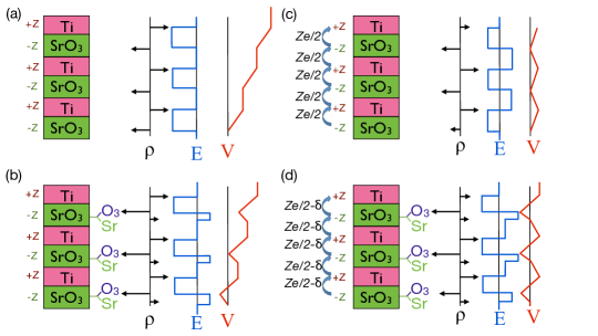
Motivated by the above question, in this article we investigate the surface electronic structure of STO (111) slabs. Along the [111] direction, a STO slab consists of alternating stacks of nominally charged (Ti)4+ and (SrO3)4- layers, which already lead to a divergent electrostatic potential, even in the absence of a LAO overlayer (Fig. 1). This is in sharp contrast to a STO (001) slab, which consists of alternating charge neutral layers of SrO and TiO2. Furthermore, the presence of multivalent transition metal ions (Ti) suggests that electronic reconstruction can also take place in STO (111). Hence, STO (111) slabs offer us a unique opportunity for studying both the polar distortion and electronic reconstruction in a chemically homogeneous system.
Our work is also relevant to the recent experimental and theoretical progress on oxide (111) interfaces and surfaces. Experimental studies have reported the growth of Ti-rich STO (111) surface Biswas et al. (2011) and the creation of 2DEGs at (111) interfaces in the LAO/STO system, with carrier densities comparable to the [001] direction. Herranz et al. (2012); Annadi et al. (2013); eom Theoretically, exotic topological phases such as the quantum spin Hall state have also been predicted for cubic perovskite (111) bilayers. Xiao et al. (2011); Yang et al. (2011); Rüegg and Fiete (2011); Okamoto (2013) Understanding the surface electronic properties of the STO (111) slabs will have important implications for these phenomena as well.
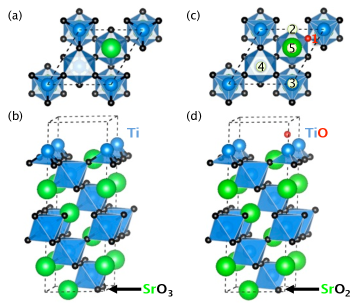
Using density functional theory (DFT), we study STO (111) slabs of various thicknesses and different surface terminations. We show that for Ti-terminated STO slabs (Figs. 2a and 2b) it is indeed possible to create a 2DEG. However, the carrier density of the 2DEG displays a strong thickness dependence due to the competition between electronic reconstruction and polar distortion. Our calculations suggest that relatively thick slabs ( layers) are required to reach the ideal carrier density (2 electrons/surface unit cell) expected from the nominal charge counting argument. In contrast, we find that the TiO-terminated slab (Figs. 2c and 2d) exhibits no charge transfer to the surface. This is because the surface oxygen functions to nullify any potential that could develop across the STO slab. A thermodynamic stability analysis shows that the Ti-terminated STO slab can be stable, albeit within a very narrow region of phase space. Our results show that both electronic reconstruction and polar distortions must be taken into account when analyzing the 2DEG behavior for (111) and (110) interfaces. Herranz et al. (2012)
II Methodology
In this work we examine STO (111) slabs with various thickness and two surface terminations: Ti (top)/SrO3 (bottom)-terminated (referred to as Ti-terminated) and TiO(top)/SrO2(bottom) terminated (referred to as TiO-terminated). Both are depicted in Fig. 2.
The electronic ground-state calculations were performed using DFT with the local density approximation (LDA) for exchange and correlation as implemented in the quantum espresso simulation package. Giannozzi et al. (2009) We employ ultrasoft pseudopotentialsVanderbilt (1990) including semicore electrons for O (), Sr () and Ti (). To account for strong electronic correlations we use a Hubbard term (LDA+U). Anisimov et al. (1991) For all calculations, a Hubbard = 5 eV for Ti states was found to be appropriate. For each slab a 11 in-plane periodicity with a vacuum region of 15 Å was used. A cutoff energy of 80 Ry and a Monkhorst-Pack special -point mesh of 881 for the Brillouin zone integration was found to be sufficient to obtain less than 10 meV/atom convergence. We applied a dipole correctionBengtsson (1999); Meyer and Vanderbilt (2001) to set the electric field in the vacuum region to zero. Structural optimizations were performed by fixing the in-plane lattice constant to that of the theoretical bulk STO lattice constant ( = 3.85Å). All ions were then relaxed until the Hellmann-Feynman forces were less than 10 meV/Å.
To analyze the thermodynamic stability of different surface terminations, we adopt a symmetric slab approach, i.e., the same termination on both sides. The thermodynamic analysis was performed using the generalized gradient approximations (GGA), as it usually gives more accurate formation energies, relative to experiments, than LDA.
III Electronic structure
III.1 Ti-Termination

We first consider the ideal Ti-terminated STO (111) slab, which consists of alternating stacks of Ti and SrO3 layers with nominal charges of and , respectively. Figure 3a shows the typical layer-projected DOS for a slab with 6 layers of SrTiO3 unit. We observe the occurrence of a surface metallic state for the top surface layer (Ti surface). This is similar to the results for the STO (110) surfaceBottin et al. (2003) and with previous semi-empirical Hartree-Fock calculations for the STO (111) surface.Pojani et al. (1999a, b) The atomic projected DOS indicates that these surface states are comprised mainly of Ti and orbitals. The excess electrons are derived from the depletion of the valence band of the bottom layer due to the depopulation of O orbitals. This can be clearly seen from the orbital dependent electronic band structure, shown in Fig. 3b. The dispersive energy bands clearly indicate that those excess charges are mobile carriers.
The number of excess electrons (holes) at the surface is obtained by performing an integration of the layer-averaged orbital projected DOS in a small neighborhood below (above) the Fermi level. Stengel and Vanderbilt (2009) (N.B. this typically underestimates the electron count relative to the total DOS by 0.1 e-.) For the 6-layer slab, we found a total transfer of 0.7 electrons per surface unit cell. However, if electronic reconstruction is the only working mechanism, nominal charge counting dictates that there should be two electrons per unit cell transferred from the SrO3 surface to the Ti surface (Fig. 1c). This is a strong indication of the vital role polar distortions Wang et al. (2009); Hamann et al. (2006); Okamoto et al. (2006) play in avoiding the polar catastrophe in oxide heterostructures. Pentcheva and Pickett (2009); Nakagawa et al. (2006).
To analyze the effect of the polar distortions, we have calculated the total transferred charge between the surface layers for different layer thicknesses for both the relaxed and the unrelaxed systems (Fig. 4). There are two main features. First, there is a critical thickness (3 layers) above which electronic reconstruction between the surfaces takes place, as indicated by the appearance of a 2DEG. Second, we observe a smooth increase in transferred charge with a thickness dependence for the relaxed system, which is in sharp contrast to the abrupt increase of transferred charge with very little thickness dependence for the unrelaxed system. We also note that for the unrelaxed structure, the transferred charge is very close to 2 electrons per unit cell.
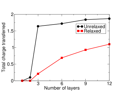
The origin of the critical thickness can be explained by comparing this situation to the LAO/STO (001) heterostructure counterpart. It is well established that for these systems above an overlayer thickness of 3 layers, there is an occurrence of a 2DEG.Thiel et al. (2006) There the polar catastrophe is built up in the LAO overlayer and electronic reconstruction occurs when the divergent potential exceeds the band gap of STO. A similar effect occurs for the STO (111) slab. When the slab is thick enough to make the divergence in potential comparable to the band gap an electronic reconstruction occurs. This is clearly seen in our results for the unrelaxed surfaces (Fig. 4). In these systems, we observe a transfer of two electrons between the surfaces once the layer thickness is beyond a critical thickness of 2 layers. This is very abrupt and as immediate as the closing of the band gap and is a consequence of the fact that the electronic reconstruction is the only mechanism available for countering the polar catastrophe in the unrelaxed slabs.
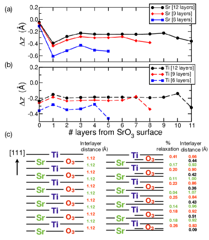
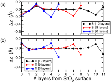
More interestingly, the thickness dependence of the magnitude of the charge transfer can be attributed to the effect of polar distortions. Figures 5a and 5b depict the layer-by-layer off-center (polar) distortions, , of Sr and Ti atoms, respectively, for Ti-terminated slabs of varying STO thicknesses. As can be seen from Fig. 5, the net effect of the (111) surface geometry and the Ti-termination is to polarize the individual layers of SrO3 and Ti layers relative to their respective oxygen cages. For all slab thicknesses, we find that in the middle of the slab there is a nearly constant shift of Ti and Sr relative to their corresponding oxygen layers, with the magnitude of the displacements decreasing with slab thickness. More important are the large off-center displacements for the surface Ti cations. Figure 5c shows a schematic of the effect of relaxation for 6 layers of the Ti-terminated STO slab with the percentage relaxation calculated which emphasizes the large surface distortions (N.B. these large relaxations are similar to other oxides).
The net effect of such surface dipoles is to counter the divergent potential across the slab. As the thickness of the slabs increase, however, we observe a decrease in the magnitude of these distortions. Below three layers the polar distortions are able to completely cancel out the polar catastrophe. As the thickness is increased, it becomes more energetically favorable to have an increase in the transferred charge and a decrease in polar distortion. We infer from the trend in Fig. 4 that for very thick STO slabs, the total amount of transferred electrons will converge to two electrons per unit cell after relaxation, just like in the case of the unrelaxed system. The competition between the electronic reconstruction and polar distortion is illustrated in Fig. 1.
III.2 TiO-Termination
Next we consider the TiO-termination of the STO (111) slab, which is made by transferring one O atom from the bottom SrO3 terminated surface to the top Ti terminated surface, as shown in Figs. 2c and d. When we remove one O atom from the SrO3 layer, the 6 identical O sites around the Sr atom are broken into a group of 4 identical sites and 2 identical O ”vacant” sites. To identify the most stable location for placing the O atom on the Ti termination, we compared the energies of 5 possible high symmetry sites as shown in Fig. 2c, and found that the O vacant site (1) is the preferred site.
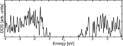
We are interested in this situation because according to the polar catastrophe argument, one should not expect any significant electron transfer between the surfaces as the transfer of one O atom between the surfaces should stabilize the system. An analysis of the total DOS (see total DOS for 6 layers of STO in Fig. 6) confirms that the system is indeed insulating for all STO layer thicknesses studied ( 6, 9, 12).
From this we note that there is no charge transfer between any bulk layers, similar to the Ti-terminated case. Nevertheless, we find a striking difference between the TiO- and Ti-terminated surfaces. In particular, in the case of the TiO-terminated surfaces there are no electrons transferred between the surface layers. Here, the polar catastrophe is avoided without any contribution from electronic reconstruction, unlike the case of the Ti-termination.
The atomic relaxation for each STO layer for different layer thickness of STO for the TiO-termination is shown in Fig. 7. Here we see that, unlike the Ti-terminated slabs, the bulk Ti and Sr cations exhibit negligible off-center displacements. Such displacements are indicative of having a reduced electric potential across the slab. However a larger polar distortion develops on the topmost plane of Ti ions, which is a local relaxation effect. To conclude, the effect of polar distortion in this case is much less compared to the Ti-termination (Fig. 5) as the transfer of one oxygen atom is effective in screening the polarization, with the help of some local relaxation. This is in agreement with the observation of the lack of charge transfer for different thicknesses for this system.
IV Thermodynamic stability
The imminent question is the relative thermodynamic stability of these different surface terminations. In this section we analyze the thermodynamic stability of the various terminations of the STO (111) surface, following the formalism proposed by F. Bottin et.al. Bottin et al. (2003) The energy required to split a crystal in half with complementary surfaces is called the cleavage energy. The cleavage energy (Ecl) per surface area for the unrelaxed Ti/SrO3 terminations and unrelaxed TiO/SrO2 terminations respectively are defined in the following
| (1) | |||
where Ebulk stands for the total energy of the bulk STO system, n the total number of STO layers and denotes the surface area. Here E is the energy of termination, with being either Ti, SrO3, TiO or SrO2.
Since the cleavage energy does not distinguish between the two complementary surfaces, we define the surface energy, , which is a measure of the stability of the surface with respect to bulk as:
| (2) | ||||
Table 1 shows the cleavage energy, relaxation energy and the surface energy for different terminations. The values for cleavage energy are in good agreement with previous first principles calculations for STO (111) surfaces. Eglitis (2012)
| SrO3 | Ti | SrO2 | TiO | |
|---|---|---|---|---|
| Ecl | 6.62 | 6.62 | 4.58 | 4.58 |
| Erel | -0.27 | -1.45 | -1.54 | -1.69 |
| 6.36 | 5.17 | 3.04 | 2.89 |
However this definition of surface energy excludes the possibility of contact with matter reservoir. Hence we compute the surface grand potential,
| (3) |
which is a measure of the excess energy of a symmetric system exposing a termination of a given composition, to a reservoir. The quantities , , in Eq. (3) are the chemical potentials of the Ti, Sr and O atomic species, respectively, and , , are the number of Ti, Sr and O atoms in the slab. The chemical potential of the bulk STO system () can be written as the sum of chemical potentials of individual species in the crystal:
| (4) |
When the surface is in equilibrium with the bulk, we have = Ebulk. Using this and Eq. (4) we can rewrite the surface grand potential in Eq. (3) as:
| (5) | ||||
From this we observe that the range of accessible values for the surface grand potential depends on the maximum and minimum values of and chemical potentials. The possible variations in reflect the experimental growth conditions. Under the O rich condition and for the Sr rich condition . Defining and we obtain
| (6) |
The ranges of the two independent parameters, and can be determined using the following set of conditions. In order to avoid the elements precipitating into Sr bulk, Ti bulk and oxygen gas, the upper bounds are set by , & . The lower bounds are obtained using:
| (7) |
where the formation energy () is defined as
| (8) |
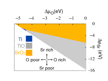
Figure 8 shows the relative stability of different terminations in the (,) plane after computing . The shaded area shows the region in the chemical potential phase space where a particular termination is most stable. We observe that the SrO2-SrO2 termination is most stable under O and Sr rich condition. When is lowered, the TiO-TiO termination becomes the most stable surface. However for low oxygen pressure, there is also a region where the Ti termination is stable, which implies that it is possible to observe the effect of electronic reconstruction by tuning the experimental conditions for STO (111) surface. It should be noted that for the STO (111) surface a stable Ti-rich surface has already been observed (albeit without any knowledge of O content).Biswas et al. (2011) Nevertheless, these results highlight the possibility of creating the Ti-terminated surface and may have specific consequences for the electronic states that could be created at a heterostructure interface.
V Conclusion
In summary, we have studied STO (111) slabs of various thicknesses and different surface terminations using density functional theory. We observe that for the Ti-SrO3 terminated STO (111) slab there is charge redistribution which is dominated by the transfer of electrons from the SrO3 terminated surface to the Ti surface, giving rise to a metallic surface states for this configuration. The carrier density of the 2DEGs display a strong thickness dependence due to the competition between electronic reconstruction and polar distortions. In comparison, for the TiO-terminated surface, no such surface states exist and the compensation mechanism is dominated by the new surface boundary conditions created by the transfer of an O ion from one surface to the other. By studying the relative stability of these different terminations we observe that the Ti termination can indeed be stabilized depending upon the experimental conditions. Naturally, the ability to tune the magnitude of charge transfer/compensation at an oxide surface/interface has consequences on numerous applications including surface catalysis and oxide electronics as well as important implications for novel phenomena such superconductivity and magnetism in confined dimensions.
Acknowledgements.
We would like to thank Marek Skowronski, Michael Widom, Satoshi Okamoto and Wenguang Zhu for useful discussions. This work was supported by AFOSR Grant No. FA9550-12-1-0479 (N.S. and D.X.), and by the U.S. Department of Energy, Office of Basic Energy Sciences, Materials Sciences and Engineering Division (D.X., H.D. and V.R.C.) and the Office of Science Early Career Research Program (V.R.C). N.S. acknowledges support through the ASTRO program at ORNL. This research used resources of the National Energy Research Scientific Computing Center, supported by the Office of Science, US Department of Energy under Contract No. DEAC02-05CH11231, and Pittsburgh Supercomputing Center’s Blacklight system, supported by NSF Grant No. OCI-1041726, which is part of the Extreme Science and Engineering Discovery Environment (XSEDE), supported by NSF Grant No. OCI-1053575.References
- Ohtomo and Hwang (2004) A. Ohtomo and H. Y. Hwang, Nature 427, 423 (2004).
- Hwang et al. (2012) H. Y. Hwang, Y. Iwasa, M. Kawasaki, B. Keimer, N. Nagaosa, and Y. Tokura, Nat. Mater. 11, 103 (2012).
- Seo et al. (2007) S. S. A. Seo, W. S. Choi, H. N. Lee, L. Yu, K. W. Kim, C. Bernhard, and T. W. Noh, Phys. Rev. Lett. 99, 266801 (2007).
- Reyren et al. (2007) N. Reyren, S. Thiel, A. D. Caviglia, L. F. Kourkoutis, G. Hammerl, C. Richter, C. W. Schneider, T. Kopp, A.-S. Rüetschi, D. Jaccard, et al., Science 317, 1196 (2007).
- Brinkman et al. (2007) A. Brinkman, M. Huijben, M. van Zalk, J. Huijben, U. Zeitler, J. C. Maan, W. G. van der Wiel, G. Rijnders, D. H. A. Blank, and H. Hilgenkamp, Nat. Mater. 6, 493 (2007).
- Ben Shalom et al. (2010) M. Ben Shalom, M. Sachs, D. Rakhmilevitch, A. Palevski, and Y. Dagan, Phys. Rev. Lett. 104, 126802 (2010).
- King et al. (2012) P. D. C. King, R. H. He, T. Eknapakul, P. Buaphet, S.-K. Mo, Y. Kaneko, S. Harashima, Y. Hikita, M. S. Bahramy, C. Bell, et al., Phys. Rev. Lett. 108, 117602 (2012).
- Thiel et al. (2006) S. Thiel, G. Hammerl, A. Schmehl, C. W. Schneider, and J. Mannhart, Science 313, 1942 (2006).
- Cen et al. (2008) C. Cen, S. Thiel, G. Hammerl, C. W. Schneider, K. E. Andersen, C. S. Hellberg, J. Mannhart, and J. Levy, Nat Mater 7, 298 (2008).
- Meevasana et al. (2011) W. Meevasana, P. D. C. King, R. H. He, S. K. Mo, M. Hashimoto, A. Tamai, P. Songsiriritthigul, F. Baumberger, and Z. X. Shen, Nat. Mater. 10, 114 (2011).
- Mannhart and Schlom (2010) J. Mannhart and D. G. Schlom, Science 327, 1607 (2010).
- Assmann et al. (2013) E. Assmann, P. Blaha, R. Laskowski, K. Held, S. Okamoto, and G. Sangiovanni, Phys. Rev. Lett. 110, 078701 (2013).
- Siemons et al. (2007) W. Siemons, G. Koster, H. Yamamoto, W. A. Harrison, G. Lucovsky, T. H. Geballe, D. H. A. Blank, and M. R. Beasley, Phys. Rev. Lett. 98, 196802 (2007).
- Nakagawa et al. (2006) N. Nakagawa, H. Y. Hwang, and D. A. Muller, Nat. Mater. 5, 204 (2006).
- Pentcheva and Pickett (2009) R. Pentcheva and W. E. Pickett, Phys. Rev. Lett. 102, 107602 (2009).
- Bristowe et al. (2009) N. C. Bristowe, E. Artacho, and P. B. Littlewood, Phys. Rev. B 80, 045425 (2009).
- Stengel and Vanderbilt (2009) M. Stengel and D. Vanderbilt, Phys. Rev. B 80, 241103 (2009).
- Bristowe et al. (2011) N. C. Bristowe, P. B. Littlewood, and E. Artacho, Journal of Physics: Condensed Matter 23, 081001 (2011).
- Stengel (2011a) M. Stengel, Phys. Rev. B 84, 205432 (2011a).
- Okamoto and Millis (2004) S. Okamoto and A. J. Millis, Nature 428, 630 (2004).
- Hamann et al. (2006) D. R. Hamann, D. A. Muller, and H. Y. Hwang, Phys. Rev. B 73, 195403 (2006).
- Okamoto et al. (2006) S. Okamoto, A. J. Millis, and N. A. Spaldin, Phys. Rev. Lett. 97, 056802 (2006).
- Cooper (2012) V. R. Cooper, Phys. Rev. B 85, 235109 (2012).
- Takizawa et al. (2011) M. Takizawa, S. Tsuda, T. Susaki, H. Y. Hwang, and A. Fujimori, Phys. Rev. B 84, 245124 (2011).
- Cantoni et al. (2012) C. Cantoni, J. Gazquez, F. M. Granozio, M. P. Oxley, M. Varela, A. R. Lupini, S. J. Pennycook, C. Aruta, U. S. di Uccio, P. Perna, et al., Adv. Mater. 24, 3952 (2012).
- Wang et al. (2009) Y. Wang, M. K. Niranjan, S. S. Jaswal, and E. Y. Tsymbal, Phys. Rev. B 80, 165130 (2009).
- Stengel (2011b) M. Stengel, Phys. Rev. B 106, 136803 (2011b).
- Biswas et al. (2011) A. Biswas, P. B. Rossen, C.-H. Yang, W. Siemons, M.-H. Jung, I. K. Yang, R. Ramesh, and Y. H. Jeong, Appl. Phys. Lett. 98, 051904 (2011).
- Herranz et al. (2012) G. Herranz, F. Sánchez, N. Dix, M. Scigaj, and J. Fontcuberta, Sci. Rep. 2, 758 (2012).
- Annadi et al. (2013) A. Annadi, Q. Zhang, X. Renshaw Wang, N. Tuzla, K. Gopinadhan, W. M. Lü, A. Roy Barman, Z. Q. Liu, A. Srivastava, S. Saha, et al., Nat. Commun. 4, 1838 (2013).
- (31) M. Rzchowski and C.-B. Eom (private communications).
- Xiao et al. (2011) D. Xiao, W. Zhu, Y. Ran, N. Nagaosa, and S. Okamoto, Nat. Commun. 2, 596 (2011).
- Yang et al. (2011) K.-Y. Yang, W. Zhu, D. Xiao, S. Okamoto, Z. Wang, and Y. Ran, Phys. Rev. B 84, 201104 (2011).
- Rüegg and Fiete (2011) A. Rüegg and G. A. Fiete, Phys. Rev. B 84, 201103 (2011).
- Okamoto (2013) S. Okamoto, Phys. Rev. Lett. 110, 066403 (2013).
- Giannozzi et al. (2009) P. Giannozzi, S. Baroni1, N. Bonini, M. Calandra, R. Car, C. Cavazzoni, D. Ceresoli, G. L. Chiarotti, M. Cococcioni, I. Dabo, et al., J. Phys.: Cond. Matt. 21, 395502 (2009).
- Vanderbilt (1990) D. Vanderbilt, Phys. Rev. B 41, 7892(R) (1990).
- Anisimov et al. (1991) V. I. Anisimov, J. Zaanen, and O. K. Andersen, Phys. Rev. B 44, 943 (1991).
- Bengtsson (1999) L. Bengtsson, Phys. Rev. B 59, 12301 (1999).
- Meyer and Vanderbilt (2001) B. Meyer and D. Vanderbilt, Phys. Rev. B 63, 205426 1 (2001).
- Bottin et al. (2003) F. Bottin, F. Finocchi, and C. Noguera, Phys. Rev. B 68, 035418 (2003).
- Pojani et al. (1999a) A. Pojani, F. Finocchi, and C. Noguera, Appl. Surf. Sc. 142, 177 (1999a).
- Pojani et al. (1999b) A. Pojani, F. Finocchi, and C. Noguera, Surf. Sci. 442, 179 (1999b).
- Eglitis (2012) R. I. Eglitis, in Nanodevices and Nanomaterials for Ecological Security, edited by Y. N. Shunin and A. E. Kiv (Springer Science+Business Media, Dordrecht, 2012), p. 125.